Ariens 921031 Manuel utilisateur
- Catégorie
- Souffleuses à neige
- Taper
- Manuel utilisateur

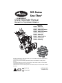
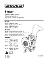
Owner/Operator Manual
Manuel Du Propriétaire/Utilisateur
Models
921013 – Deluxe 30
(Serial No. 35000 and up)
921017 – Deluxe 24 Platinum
(Serial No. 35000 and up)
921018 – Deluxe 30 Platinum
(Serial No. 35000 and up)
921022 – Deluxe 28
(Serial No. 35000 and up)
921023 – Deluxe Track 28
(Serial No. 35000 and up)
921031 – Deluxe 24
(Serial No. 101 and up)
921 Series
Sno-Thro
®
04335900B 8/11
Printed in USA
ENGLISH
FRANÇAIS
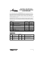
Gasoline containing up to 10% ethanol (E10) or up to 10% MTBE (methyl tertiary butyl ether) is
acceptable for use in this machine.
The use of any gasoline exceeding 10% ethanol (E10) or 10% MTBE will void the product
warranty.
Il est possible d’utiliser de l’essence contenant jusqu’à 10% d’éthanol (E10) ou 10% de MTBE
(éther méthyl-tertiobutylique) sur cette machine.
L’utilisation d’une essence contenant plus de 10% d’éthanol (E10) ou de 10% de MTBE annulent
la garantie
.

GB - 2
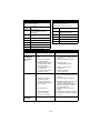
SAFETY. . . . . . . . . . . . . . . . . . . . . . . . . . 4
ASSEMBLY . . . . . . . . . . . . . . . . . . . . . . . 8
CONTROLS and FEATURES . . . . . . . . 14
OPERATION . . . . . . . . . . . . . . . . . . . . . 16
MAINTENANCE . . . . . . . . . . . . . . . . . . 22
SERVICE AND ADJUSTMENTS . . . . . 25
STORAGE. . . . . . . . . . . . . . . . . . . . . . . 34
SERVICE PARTS . . . . . . . . . . . . . . . . . 34
ACCESSORIES. . . . . . . . . . . . . . . . . . . 34
TROUBLESHOOTING . . . . . . . . . . . . . 35
SPECIFICATIONS. . . . . . . . . . . . . . . . . 36
WARRANTY . . . . . . . . . . . . . . . . . . . . . 38
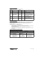
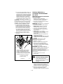
NON-ENGLISH MANUALS
Manuals in languages other than
English may be obtained from your
Dealer. Visit your dealer or
www.ariens.com for a list of
languages available for your
equipment.
Manuals printed in languages other
than English are also available as a
free download on our website:
http://www.ariens.com
MANUALES EN IDIOMAS
DIFERENTES DEL INGLES
Puede obtener manuales en
idiomas diferentes del inglés en su
distribuidor. Visite a su distribuidor
o vaya a www.ariens.com para
obtener una lista de idiomas
disponibles para su equipo.
También puede imprimir manuales
en idiomas diferentes del inglés
descargándolos gratuitamente de
nuestra página Web:
http://www.ariens.com
MANUELS NON ANGLAIS
Des manuels dans différentes
langues sont disponibles chez
votre revendeur. Rendez-vous
chez votre revendeur ou allez sur
le site www.ariens.com pour
consulter la liste des langues
disponibles pour votre équipement.
Les manuels imprimés dans des
langues différentes de l’anglais
sont également disponibles en
téléchargement gratuit sur notre
site Web:
http://www.ariens.com
MANUALS
Before operation of unit, carefully and
completely read your manuals. If used
improperly, this unit could be dangerous and
cause personal injury or property damage.
The contents will provide you with safety
instructions for the safe use of your unit
during normal operation and maintenance.
All reference to left, right, front, or rear are
given from operator standing in operation
position and facing the direction of forward
travel.
ENGINE MANUAL
The engine on this unit is covered by a
separate manual specific to the engine. This
manual is included in the literature package
that shipped with the unit. Refer to this
manual for engine service recommendations.
If the engine manual is not available, contact
the engine manufacturer for a replacement
manual.
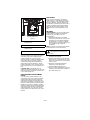
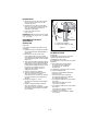
MODEL AND SERIAL NUMBERS
When ordering replacement parts or making
service inquiries, know the Model and Serial
numbers of your unit and engine.
Numbers are located on the product
registration form in the unit literature
package. They are printed on a serial number
label, located on the frame of your unit.
TABLE OF CONTENTS
INTRODUCTION

GB - 3
• Record Unit Model and Serial
numbers here.
• Record Engine Model and Serial
numbers here.
PRODUCT REGISTRATION
The Ariens dealer must register the product
at the time of purchase. Registering the
product will help the company process
warranty claims or contact you with the latest
service information. All claims meeting
requirements during the limited warranty
period will be honored, whether or not the
product registration card is returned. Keep a
proof of purchase if you do not register your
unit.
Customer Note: If the dealer does not
register your product, please fill out, sign, and
return the product registration card to Ariens
or go to www.ariens.com.
UNAUTHORIZED REPLACEMENT
PARTS
Use only Ariens replacement parts. The
replacement of any part on this vehicle with
anything other than an Ariens authorized
replacement part may adversely affect the
performance, durability, or safety of this unit
and may void the warranty. Ariens disclaims
liability for any claims or damages, whether
warranty, property damage, personal injury or
death arising out of the use of unauthorized
replacement parts. To locate your nearest
Ariens Dealer, go to www.ariens.com on the
internet.
DISCLAIMER
Ariens reserves the right to discontinue,
make changes to, and add improvements
upon its products at any time without public
notice or obligation. The descriptions and
specifications contained in this manual were
in effect at printing. Equipment described
within this manual may be optional. Some
illustrations may not be applicable to your
unit.
DELIVERY
Customer Note: If you have purchased this
product without complete assembly and
instruction by your retailer, it is your
responsibility to:
1. Read and understand all assembly
instructions in this manual. If you do not
understand or have difficulty following
the instructions, contact your nearest
Ariens Dealer for assistance. Make sure
all assembly has been properly
completed.
NOTE: To locate your nearest Ariens Dealer,
go to www.ariens.com on the Internet.
2. Understand all Safety Precautions
provided in the manuals.
3. Review control functions and operation
of the unit. Do not operate the Sno-Thro
unless all controls function as described
in this manual.
4. Review recommended lubrication,
maintenance and adjustments.
5. Review Limited Warranty Policy.
6. Fill out a Product Registration Card and
return the card to the Ariens Company or
go to www.ariens.com.
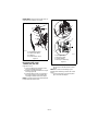
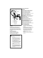
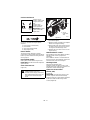
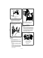
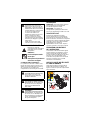
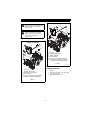
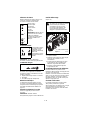
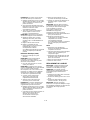
Figure 1
Serial Number Label
OS7005
WARNING: Improper assembly or
adjustments can cause serious
injury.

GB - 4
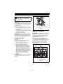
SAFETY ALERTS
Look for these symbols to point
out important safety
precautions. They mean:
Attention!
Personal Safety Is
Involved!
Become Alert!
Obey The Message!
The safety alert symbols above and signal
words below are used on decals and in this
manual. Read and understand all safety
messages.
NOTATIONS
NOTE: General reference information for
proper operation and maintenance practices.
IMPORTANT: Specific procedures or
information required to prevent damage to
unit or attachment.
PRACTICES AND LAWS
Practice usual and customary safe working
precautions, for the benefit of yourself and
others. Understand and follow all safety
messages. Be alert to unsafe conditions and
the possibility of minor, moderate, or serious
injury or death. Learn applicable rules and
laws in your area. Always follow the practices
set forth in this manual.
REQUIRED OPERATOR TRAINING
Original purchaser of this unit was instructed
by the seller on safe and proper operation. If
unit is to be used by someone other than
original purchaser; loaned, rented or sold,
ALWAYS provide this manual and any
needed safety training before operation.
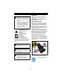
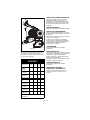
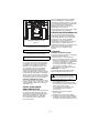
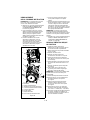
SAFETY DECALS AND LOCATIONS
ALWAYS replace missing or damaged Safety
Decals. Refer to Figure 2 below for Safety
Decal locations.
1. WARNING!
SAFETY
WARNING: To avoid injury to
hands and feet, always disengage
clutches, shut off engine, and wait
for all movement to stop before
unclogging or working on snow
thrower.
Hand contact with the rotating
impeller is the most common cause
of injury associated with snow
throwers. Never use your hand to
clean out the discharge chute.
Keep hands and feet away from
auger and impeller.
DANGER: IMMINENTLY
HAZARDOUS SITUATION! If not
avoided, WILL RESULT in death or
serious injury.
WARNING: POTENTIALLY
HAZARDOUS SITUATION! If not
avoided, COULD RESULT in death
or serious injury.
CAUTION: POTENTIALLY
HAZARDOUS SITUATION! If not
avoided, MAY RESULT in minor or
moderate injury. It may also be
used to alert against unsafe
practices.
Read Owner/Operator Manual.
Figure 2
1
2
3
OL1801

GB - 5
2. DANGER!
3. DANGER!
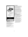
EMISSION CONTROL SYSTEM
This equipment and/or its engine may include
exhaust and evaporative emissions control
system components required to meet U.S.
Environmental Protection Agency (EPA)
and/or California Air Resources Board
(CARB) regulations. Tampering with
emission controls and components by
unauthorized personnel may result in severe
fines or penalties. Emission controls and
components can only be adjusted by an
Ariens Company dealer or an authorized
engine manufacturer's service center.
Contact your Ariens Company Equipment
Retailer concerning emission controls and
component questions.
SAFETY RULES
Read, understand, and follow all safety
practices in Owner/Operator Manual before
beginning assembly or operating. Failure to
follow instructions could result in personal
injury and/or damage to unit.
ALWAYS remove key and/or wire from spark
plug before assembly, maintenance or
service. Unintentional engine start up can
cause death or serious injury.
Complete a walk around inspection of unit
and work area to understand:
• Work area • Your unit • All safety decals
ALWAYS check overhead and side
clearances carefully before operation.
ALWAYS be aware of traffic when operating
along streets or curbs.
Keep children and people away. Keep
children out of work area and under watchful
care of a responsible adult.
NEVER allow children to operate or play on
or near unit. Be alert and shut off unit if
children enter area.
Keep people away from unit
while operating. Keep children
out of work area and under
watchful care of a responsible
adult.
Never direct discharge towards
persons or property that may be
injured or damaged by thrown
objects.
Stop engine, remove key, read
manual before making any
repairs or adjustments.
Wear appropriate hearing
protection.
ONLY use clean-out tool to
clear blockages. NEVER use
your hands.
ROTATING PARTS! ONLY use
clean-out tool to clear
blockages. NEVER use your
hands. High speed impeller
rotates below discharge
opening. Wait for all moving
parts to stop before removing
clogs or servicing.
OL4370
OL0910
OL4010
OL4690
OS6610
ROTATING PARTS.
Keep clear of auger while
engine is running.
• Read Operator’s Manual.
• Allow operation only by
properly trained adult, never
children.
• Stop engine and remove
ignition key prior to leaving
the operator’s position for
any reason.
• Keep all controls, guards
and safety devices properly
serviced and functional.
• Never direct discharge
towards persons or property
that may be injured or
damaged by thrown objects.
OS2080

GB - 6
DO NOT allow adults to operate unit without
proper training. Only trained adults may
operate unit. Training includes actual
operation.
Keep area of operation clear of all toys, pets,
and debris. Thrown objects can cause injury.
Check for weak spots on docks, ramps or
floors. Avoid uneven work areas and rough
terrain. Stay alert for hidden hazards.
DO NOT operate near drop-offs, ditches, or
embankments. Unit can suddenly turn over if
a wheel is over the edge of a cliff or ditch, or if
an edge caves in.
Falling snow, fog, etc. can reduce vision and
cause an accident. Operate unit only when
there is good visibility and light.
NEVER operate unit after or during the use of
medication, drugs or alcohol. Safe operation
requires your complete and unimpaired
attention at all times.
NEVER allow anyone to operate this unit
when their alertness or coordination is
impaired.
DO NOT operate unit without wearing
adequate winter outer garments. Wear
adequate safety gear, including safety
glasses with side shields, and protective
gloves. Wear proper footwear to improve
footing on slippery surfaces.
DO NOT wear loose clothing or jewelry and
tie back hair that may get caught in rotating
parts.
Protect eyes, face and head from objects that
may be thrown from unit. Wear appropriate
hearing protection.
Avoid sharp edges. Sharp edges can cut.
Moving parts can cut off fingers or a hand.
ALWAYS keep hands and feet away from all
rotating parts during operation. Rotating parts
can cut off body parts.
NEVER place your hands or any part of your
body or clothing inside or near any moving
part while unit is running.
ALWAYS keep hands away from all pinch
points.
DO NOT touch unit parts which might be hot
from operation. Allow parts to cool before
attempting to maintain, adjust or service.
Never direct discharge towards persons or
property that may be injured or damaged by
thrown objects. Use extreme caution on
gravel surfaces. Stay alert for hidden hazards
or traffic. Adjust Skid Shoes so Scraper Blade
does not contact gravel.
DO NOT throw snow any higher than
necessary.
Deflected materials can cause injury and
property damage.
Always stand clear of the discharge area
when operating this unit.
Fumes from engine exhaust can cause injury
or death. DO NOT run engine in an enclosed
area. Always provide good ventilation.
ALWAYS disengage attachment, stop unit
and engine, remove key and allow moving
parts to stop before leaving operator’s
position.
ROTATING AUGER CAN CAUSE SERIOUS
INJURY. NEVER ATTEMPT TO UNCLOG
OR CLEAN UNIT WHILE ENGINE IS
RUNNING.
Read, understand, and follow all instructions
in the manual and on the machine before
starting.
Understand:
• How to operate all controls.
• The functions of all controls.
• How to STOP in an emergency.
Before starting engine, disengage control(s).
Use only approved extension cords and
receptacles when starting units equipped with
electric starter. DO NOT connect electric
starter cord to any wiring system that is not a
three-wire grounded system.
ALWAYS allow unit and engine to adjust to
outdoor temperatures before clearing snow.
DO NOT overload the machine capacity by
attempting to operate or to clear snow at too
fast a rate.
Slow down and turn corners slowly.
Do not operate in reverse unless absolutely
necessary. ALWAYS back up slowly. Always
look down and behind before and while
backing.
Disengage attachment drive when traveling
from one work area to another.
Abnormal Vibrations are a warning of trouble.
Striking a foreign object can damage unit.
Immediately stop unit and engine. Remove
key and wait for all moving parts to stop.
Remove wire from spark plug. Inspect unit
and make any necessary repairs before
restart.
Before cleaning, removing clogs or making
any inspections, repairs, etc.: disengage
clutch(es), stop unit and engine, remove key,
allow moving parts to stop. Allow hot parts to
cool.
Run unit a few minutes after clearing snow to
prevent freeze-up of attachment.
Disengage attachment when not in use.
Disengage all clutches before starting engine.
Adjust skid shoes to clear gravel or crushed
rock surfaces safely.
Never leave a running unit unattended.
ALWAYS shut off engine before leaving unit.
ALWAYS remove key to prevent unauthorized
use.
Never carry passengers.
Check clutch and brake operation frequently.
Adjust and service as required. All motion of
drive wheels and auger/impeller must stop
quickly when control levers are released.

GB - 7
DO NOT operate on steep slopes. DO NOT
clear snow across the face of slopes. Keep all
movement on slopes slow and gradual. DO
NOT make sudden changes in speed or
direction. Use a slow speed to avoid stops or
shifts on slopes. Avoid starting or stopping on
a slope.
DO NOT park unit on a slope unless
absolutely necessary. When parking on a
slope always block the wheels.
ALWAYS shut off engine, remove key, and
close fuel shut-off valve or drain fuel when
transporting unit on a truck or trailer.
Use extra care when loading or unloading
unit onto trailer or truck.
Secure unit chassis to transport vehicle.
NEVER secure from rods or linkages that
could be damaged.
DO NOT transport machine while engine is
running.
Keep unit free of ice or other debris. Clean up
oil or fuel spills.
This product is equipped with an internal
combustion type engine. DO NOT use unit on
or near any unimproved, forest-covered or
brush covered land unless exhaust system is
equipped with a spark arrester meeting
applicable local, state or federal laws. A spark
arrester, if it is used, must be maintained in
effective working order by operator.
Fuel is highly flammable and its vapors are
explosive. Handle with care. Use only an
approved gasoline container with an
appropriately sized dispensing spout.
NO smoking, NO sparks, NO flames.
ALWAYS allow engine to cool before
servicing.
NEVER fill fuel tank when engine is running
or hot from operation.
NEVER fill or drain fuel tank indoors.
Replace fuel cap securely and clean up
spilled fuel.
Never fill containers inside a vehicle or on a
truck or trailer bed with a plastic liner. Always
place containers on the ground away from
your vehicle before filling.
When practical, remove gas-powered
equipment from the truck or trailer and refuel
it on the ground. If this is not possible, then
refuel such equipment on a trailer with a
portable container, rather than from a
gasoline dispenser nozzle.
Keep the nozzle in contact with the rim of the
fuel tank or container opening at all times until
fueling is complete. Do not use a nozzle lock-
open device.
If fuel is spilled on clothing, change clothing
immediately.
Avoid Electric Shock. Objects contacting both
battery terminals at the same time may result
in injury and unit damage. DO NOT reverse
battery connections.
Explosive Gases from battery can cause
death or serious injury. Poisonous battery
fluid contains sulfuric acid and its contact with
skin, eyes or clothing can cause severe
chemical burns.
No flames, No sparks, No smoking near
battery.
ALWAYS wear safety glasses and protective
gear near battery.
DO NOT TIP battery beyond a 45° angle in
any direction.
ALWAYS keep batteries out of reach of
children.
Battery posts, terminals and related
accessories contain lead and lead
compounds, chemicals known to the State of
California to cause cancer and reproductive
harm. Wash hands after handling.
Follow First Aid directions for contact with
battery fluid.
• External Contact: Flush with water.
• Eyes: Flush with water for at least 15
minutes and get medical attention
immediately!
• Internal Contact: Drink large quantities
of water. Follow with Milk of Magnesia,
beaten egg or vegetable oil. Get
medical attention immediately!
• In case of internal contact, DO NOT
induce vomiting!
Properly remove fuel and battery before
tipping unit up onto housing, so no spills will
occur.
Secure unit so it will not tip over during
maintenance.
ALWAYS keep protective structures, guards,
and panels in good repair, in place and
securely fastened. NEVER modify or remove
safety devices.
DO NOT change engine governor settings or
over-speed engine.
Fumes from engine exhaust can cause injury
or death. DO NOT run engine in an enclosed
area. Always provide good ventilation.
ALWAYS maintain unit in safe operating
condition. Damaged or worn out muffler can
cause fire or explosion.
Keep all hardware properly tightened. Check
shear bolts frequently.
Maintain or replace safety and instruction
labels, as necessary.
NEVER store unit with fuel in fuel tank, inside
a building where any ignition sources are
present such as hot water heaters, space
heaters, or clothes dryers. Allow the engine to
cool before storing in any enclosure.
Shut off fuel and allow engine to cool
completely before storing in closed area or
covering unit.
For extended storage, clean unit thoroughly.
See Engine Manual for proper storage.
Use only attachments or accessories
designed for your unit.
Check components frequently. If worn or
damaged, replace with manufacturer’s
recommended parts.

GB - 8
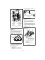
PACKAGE CONTENTS
ASSEMBLY
Tools Required:
•Pliers
• Open-End Wrenches: 3/8, 7/16, 1/2,
9/16 in. and/or Adjustable Wrench
• Tire Gauge
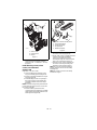
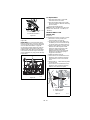
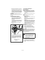
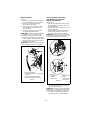
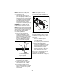
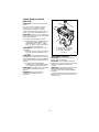
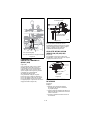
Unfold Handlebar
(Figure 5)
1. Remove the lower and loosen the upper
hardware on the handlebar assembly.
2. Loosen the hardware on the shift rod.
3. Put the speed selector lever in the
second reverse position.
4. Rotate the handlebars into operating
position.
IMPORTANT: Be careful not to damage cable
spring hooks when rotating handlebars
upward.
5. Install and tighten all hardware on the
handlebar assembly and shift rod.
6. Check tension on auger and traction
clutch cables.
ASSEMBLY
WARNING: AVOID INJURY. Read
and understand the entire Safety
section before proceeding.
WARNING: Dropping or tipping
over boxed unit could result in
personal injury or damage to unit.
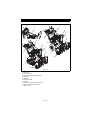
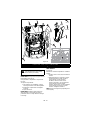
Figure 3
1. Sno-Thro Unit
2. Discharge Chute
3. Chute Crank
4. Literature Pack
5. Fuel Cap (Packaged Separately)
(921013)
1
2
4
3
OS7021
921013, 022, 023, 031
5
Figure 4
1. Sno-Thro Unit
2. Discharge Chute
3. Chute Rod
4. Literature Pack
5. Chute Control Assembly and Cable
6. Fuel Cap (Packaged Separately)
(921018)
1
2
4
3
OS7019
921017, 018
6
5

GB - 9
IMPORTANT: Cables should not be slack nor
under tension. Adjust as necessary.
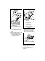
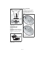
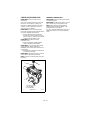
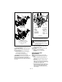
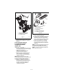
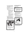
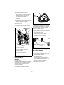
Install Discharge Chute and
Discharge Chute Crank
(921013, 022, 023, 031)
(Figures 6 and 7)
1. Grease underside of discharge chute
ring (if not already greased).
2. Remove mounting hardware from auger
housing (Figure 6).
3. Install discharge chute over opening in
the auger housing. Finger tighten the
mounting hardware removed in step 2.
NOTE: Leave discharge chute pedestal loose
to help install the chute crank.
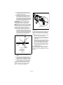
4. Insert the short end of the chute crank
into the hole in the front of the control
panel.
NOTE: Be careful not to damage nylon
bushing when attaching crank to the control
panel.
5. Connect the chute crank to the pinion
gear on chute with hairpin.
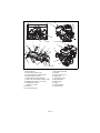
Figure 5
1. Handlebar Hardware
2. Shift Rod Hardware
3. Shift Rod
4. Speed Selector Lever
OS7030
1
3
2
4
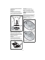
Figure 6
1. Mounting Holes
2. Discharge Chute
3. Chute Pedestal
4. Discharge Chute Ring
1
1
3
2
OS7040
OS7045
4

GB - 10
.
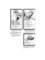
6. Orient the chute and pedestal to its most
vertical position and tighten pedestal
hardware to 15 – 31 lbf-ft (20 – 42 N•m)
(Figure 6).
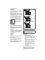
Install Discharge Chute, Chute
Control, and Chute Rod
(921017, 018)
(Figures 8, 9, 10, 11 and 12)
1. Grease underside of discharge chute
ring (if not already greased) (Figure 6).
2. Remove mounting hardware from auger
housing (Figure 6).
3. Install discharge chute over opening in
the auger housing. Finger tighten the
mounting hardware removed in step 2
(Figure 6).
NOTE: Leave discharge chute pedestal loose
to help install the chute rod and connect it to
the control assembly.
4. Remove rubber grommet from the
control panel by pinching the long-edged
sides together and pulling upward. Save
rubber grommet (Figure 8).
5. Remove and save the large hairpin from
the control assembly (Figure 8).
6. Route chute control assembly below the
crossbar of the lower handlebar
(Figure 10). Slide the lever of the
assembly through the underside of the
hole in the control panel (Figure 9).
7. Insert the chute control assembly into
the control assembly mounting hole
under the control panel (Figure 9).
NOTE: Be sure the poly liner bushing is
properly seated in the control assembly
mounting hole.
NOTE: Mounted control lever should tip
towards the engine.
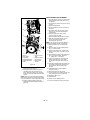
Figure 7
1. Chute Crank
2. Control Panel
3. Hairpin
1
3
OS7061
2
921013, 022, 023, 031
Figure 8
1. Chute Control Assembly Lever
2. Poly Liner Bushing
3. Control Assembly
4. Large Hairpin
5. Rubber Grommet
3
2
1
4
5

GB - 11
8. Install rubber grommet removed in
step 4, by stretching rubber grommet
over the top and around chute control
lever.
NOTE: Make sure the groove around the
entire edge of the rubber grommet is properly
seated in the hole in the control panel.
9. Remove the gear cover from the gear
assembly by removing 3/8 inch screw
and lifting up cover (Figure 10).
10. Release the gear assembly teeth by
pushing and on the upper part of the
gear lock. While the gear assembly
teeth are released, rotate the discharge
chute 90° counter-clockwise (Figure 11).
IMPORTANT: To ensure the discharge chute
follows its full range of travel, make sure the
control lever is pushed all the way to the left
before installing and pinning the chute rod.
NOTE: Do not remove the small hairpin
installed on the end of the chute rod
(Figure 10).
Figure 9
1. Chute Control Assembly Lever
2. Mounting Bracket
3. Control Assembly Mounting Hole
4. Polyliner Bushing
1
2
3
4
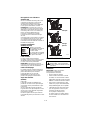
Figure 10
OS7061
1. Chute Rod
2. 3/8 inch Screw
3. Gear Cover
4. Control Assembly
5. Large Hairpin
6. Gear Assembly
7. Chute Lock Cable
8. Alignment Marks
9. Small Hairpin
10. Chute Lock Cable Hook
921017, 018
4
5
3
1
9
6
7
8
2
10
Figure 11
OS7271
Push here to release gear assembly teeth.
Rotate chute 90° counter clockwise.

GB - 12
11. Cut the cable tie that holds the gear
assembly together. Make sure the gear
components stay in place.
12. Align the holes on the end of the chute
rod with the alignment marks on the
gear assembly and slide the chute rod
end, without a small hairpin, through the
gear assembly, through the hook on the
chute lock cable, and into the hex hole in
the control assembly (Figure 10).
IMPORTANT: The hook on the chute lock
cable will prevent the control cable from
contacting the engine or muffler guard.
NOTE: After the chute rod has been inserted
through the hex hole in the control assembly,
placing the unit in the service position (see
Service Position on page 22) will ease
alignment and installation of the large hairpin.
13. Secure the chute rod to the control
assembly with large hairpin removed in
step 5. Use the hole location as shown
in Figure 12. Insert the large hairpin with
the loop end to the left of the chute rod
so the chute control assembly lever
follows a full range of travel.
14. Replace the gear cover removed in
step 9.
15. Orient the chute and pedestal to its most
vertical position and tighten pedestal
hardware to 15 – 31 lbf-ft (20 – 42 N•m).
16. Make sure the discharge chute rotates
left and right when you push the chute
control assembly lever left and right.
NOTE: If chute does not stay in position,
adjust as directed in Discharge Chute on
page 17, or repair before operation.
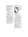
Remote Deflector Control
(Figure 14)
Connect the cable end to the cable anchor on
the discharge deflector before clipping the
cable to the cable bracket on the discharge
chute.
1. Route deflector remote cable along the
left side of the chute pedestal.
2. Insert the barrel on the cable end into
the bracket on left side of chute deflector
(Figure 14).
3. Hold seal out of the way while routing
the cable through the bracket on the left
side of the discharge chute, and then
push the cable fitting into the bracket.
4. Push the seal securely over the end of
the cable fitting to prevent water from
entering the cable.
Check deflector travel. Adjust nut on cable
end under handlebar to obtain full travel, if
necessary (see Remote Deflector Control on
page 27).
Figure 12
1. Chute Control
Assembly
2. Large Hairpin
3. Chute Rod
1
2
3
OS7157
Figure 13
OS7271

GB - 13
.
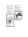
Check Function of Dual Handle
Interlock
Without the engine running, press down
(engage) both clutch levers. Release
attachment clutch lever. Attachment clutch
should remain engaged until traction clutch
lever is released, then both clutches must
disengage. If they do not, contact your Dealer
for repairs.
Check Tire Pressure
(921013, 017, 018, 022, 031)
Check tire pressure and adjust to the
pressure listed on tire sidewall.
Check Track Tension
(921023)
Check tracking of unit with the differential
locked, and tension of tracks (see Track
Tension Adjustment on page 33).
Check Auger Gearcase Oil
Check oil level in auger gearcase (see Check
Auger Gearcase on page 24).
Check Engine Crankcase Oil
IMPORTANT: The engine is shipped with oil
in crankcase. Refer to Engine Manual for
detailed instructions.
Fill Engine Fuel Tank
Fill fuel tank. DO NOT OVERFILL! See
FILLING FUEL TANK on page 19
For Model 921013, 018: Remove the plug
from the fuel tank and install the fuel cap
located in the attached bag.
Check Function of all Controls
Ensure unit runs and performs properly. Refer
to OPERATION on page 16.
Run-in Attachment Belt
1. Start unit in a well-ventilated area
according to Starting and Shut Off on
page 21.
2. Engage attachment clutch lever and run
attachment for about 15 minutes.
3. Stop unit, wait for all moving parts to
stop, and remove spark plug wire.
4. Adjust belt finger, if necessary. See
Check Belt Finger Clearance on
page 30.
5. Adjust clutch idler according to
Attachment Clutch/Brake Adjustment on
page 28.
CAUTION: Avoid injury! Explosive
separation of tire and rim parts is
possible when they are serviced
incorrectly:
• Do not attempt to mount a tire
without the proper equipment and
experience to perform the job.
• Do not inflate the tires above the
recommended pressure.
• Do not weld or heat a wheel and
tire assembly. Heat can cause an
increase in air pressure resulting
in an explosion. Welding can
structurally weaken or deform the
wheel.
• Do not stand in front or over the
tire assembly when inflating. Use a
clip-on chuck and extension hose
long enough to allow you to stand
to one side.
Figure 14
1. Cable Anchor
2. Cable End
3. Deflector Cable
4. Cable Fitting
5. Cable Bracket
1
2
3
5
4
3
OS7070

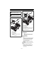
GB - 14
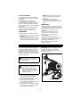
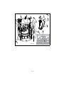
1. Skid Shoe
2. Clean-Out Tool
3. Remote Discharge Chute Deflector
4. Belt Cover
5. Headlight
6. Discharge Chute
7. Impeller
8. Chute Crank (921013, 022, 023, 031)
9. Quick Turn Chute Control Rod
(921017, 018)
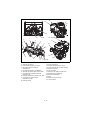
CONTROLS AND FEATURES
Figure 15
1
2
4
6
7
8
5
3
1
2
4
6
7
8
5
9
921017, 018
3

GB - 15
1. Attachment Clutch Lever
2. Speed Selector
3. Traction Drive Clutch Lever
4. Remote Wheel Lock (921013, 022)
5. Remote Deflector Control
6. Height Adjuster Trigger (921023)
7. Quick Turn Chute Control (921017, 018)
8. Handwarmers (921013, 017, 018)
9. Handwarmers Switch
(921013, 017, 018)
10. Oil Drain
11. Fuel Shut-Off Valve
12. Primer Bulb
13. Recoil Starter Handle
14. Throttle
15. Choke Control Knob
16. Ignition Key
17. Fuel Tank and Cap
18. Oil Fill/Dipstick
19. Electric Start
20. Auger
21. Auger Gearcase
22. Scraper Blade
Figure 16
12
10
14
16
11
13
15
19
19
17
13
5
9
2
3
1
6
4
7
8
20
22
21
18

GB - 16
CONTROLS AND FEATURES
See CONTROLS and FEATURES on
page 14 for all Controls and Features
locations.
Dual Handle Interlock
When Attachment Clutch and then Traction
Drive Clutch are engaged, the Attachment
Clutch will remain engaged (lever down) if
released. To stop attachment, release
Traction Drive Clutch and both clutches will
disengage.
Traction Drive Clutch -
Left Hand Lever
Squeeze the Traction
Drive Clutch Lever
against the Handlebar
(1) to engage wheel
drive for propelling unit.
Forward speed will
vary according to snow
depth and moisture
content.
Release lever (2) to
stop movement.
NOTE: When traveling to or from the area to
be cleared, press down on the handlebars
enough to raise the front of the unit slightly off
the surface. Engage the traction drive clutch
without engaging the attachment drive clutch.
Attachment Clutch -
Right Hand Lever
Squeeze Attachment
Clutch Lever against
handlebar (1) to
engage attachment.
Release both clutch
levers (2) to disengage
power and apply brake
to attachment.
IMPORTANT: If the belt squeals when the
attachment clutch lever is engaged, the
impeller may be frozen in the auger housing.
Immediately release the attachment clutch
lever and move the unit into a heated area to
thaw.
NOTE: If belt squeals when impeller turns
freely, see Attachment Clutch/Brake
Adjustment on page 28.
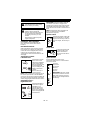
Ignition Switch
Operate the ignition switch with
the removable key. To start the
engine, turn the key to Start. To
stop the engine, turn the key to
Off.
Primer Bulb
Pushing the primer bulb
in adds fuel for easier
engine start. Refer to
Starting and Shut Off on
page 21.
Speed Selector
Position the Speed Selector in the
appropriate speed notch to control forward
and reverse travel.
Forward:
(6) Fastest
(1) Slowest
Reverse:
(1) Slow
(2) Fast
IMPORTANT: DO NOT change
motion from forward to reverse
with clutch engaged. Forward
speed can be changed without
declutching.
OPERATION
WARNING: AVOID INJURY. Read
and understand the entire Safety
section before proceeding.
WARNING: To avoid injury to hands
and feet, always disengage
clutches, shut off engine, and wait
for all movement to stop before
unclogging or working on snow
thrower.
Keep hands and feet away from
auger and impeller.
1
2
OL2701
1
2
OL2691
OS7320
OS1196
6
1
1
2

GB - 17
Choke Control Knob
1.Choke Closed
position: chokes off air
to engine for easier
start.
2.Choke Open
position: allows for
normal operation.
IMPORTANT: Gradual
ly open choke after
engine starts.
Throttle
The throttle controls the engine speed. To
increase or decrease the engine speed,
adjust to:
1. Fast (normal or warm starts)
2. Part-Throttle
3. Slow (cold weather starts)
4. Stop (engine is off)
Electric Starter
The electric starter will start a properly
choked and cranked engine when the starter
button is pushed. Refer to Starting and Shut
Off on page 21.
Recoil Starter Handle
When pulled, handle will turn engine over.
IMPORTANT: DO NOT let handle snap back
against starter.
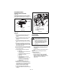
Snow Clean-Out Tool
(Figure 17)
To clear the discharge chute:
1. Shut off the engine.
2. Wait 10 seconds and make sure impeller
blades have stopped rotating.
3. Remove the snow clean-out tool (1) from
the auger housing and use it to remove
the clog from the discharge chute.
4. Replace the snow clean-out tool on the
auger housing.
Remote Deflector Control
Place deflector into position before operation.
DO NOT throw snow any higher than
necessary.
Place deflector remote in a forward notch to
throw snow lower. Place deflector remote in a
rearward notch to throw snow higher.
Discharge Chute
Discharge chute rotates 200°.
ALWAYS position discharge chute in safe
direction and angle, away from operator and
bystanders, before starting engine.
Quick Turn Chute Control
(921017, 018)
(Figure 18)
IMPORTANT: If chute does not stay in set
position, adjust as directed in Discharge
Chute on page 28, or repair before operation.
Rotate the Chute with Discharge Chute
Control (Figure 18).
WARNING: Hand contact with the
rotating impeller is the most
common cause of injury associated
with snow throwers. Never use your
hand to clean out the discharge
chute.
CHOKE
RUN
2
1
OS7275
3
2
1
Figure 17
OS7102
1. Snow
Clean-Out
Tool
1

GB - 18
IMPORTANT: DO NOT force frozen chute
controls. If frozen, take to warm place until
controls are free.
Discharge Chute Crank
(921013, 022, 023, 031)
(Figure 19)
IMPORTANT: If chute does not stay in set
position, adjust as directed in SERVICE AND
ADJUSTMENTS on page 25, or repair before
operation.
Rotate the Chute with Discharge Chute
Crank.
IMPORTANT: DO NOT force frozen chute
controls. If frozen, take to warm place until
controls are free.
Axle Lock Pin (921031)
(Figure 20)
Use the axle lock pin to lock or unlock the
right or left wheel. Lock both wheels to
increase traction; unlock one wheel to allow
for easier turning of the unit.
NOTE: Unit will not drive with both wheels
unlocked.
Figure 18
OS7105
Figure 19
OS7106
Figure 20
Wheel Unlocked
Wheel Locked
Axle Lock
Pin
OS6000

GB - 19
Remote Wheel Lock
(921013, 022)
Squeeze and release the remote wheel lock
control to lock the left wheel for better traction
when throwing snow or to unlock the left
wheel for easier steering.
NOTE: The wheel lock will not release when
under load. Do not unlock the wheel while
turning. If the wheel lock will not release, turn
the unit slightly left or right to relieve axle load
and release the axle lock.
If remote wheel lock does not lock or unlock
properly, adjust or repair before operation
(see Remote Wheel Lock on page 26).
Heated Handles (921013, 017, 018)
Turn the heated handles
switch to the ON (1)
position to activate. Turn
the switch to the OFF (2)
position to deactivate.
Scraper Blade
The scraper blade allows better contact with
the surface being cleared. It also prevents
damage to the housing from normal usage.
IMPORTANT: DO NOT allow Scraper Blade
to wear too far or Auger/Impeller housing will
become damaged.
Skid Shoes
The skid shoes control the distance between
the scraper blade and the ground. Adjust skid
shoes equally to keep blade level with the
ground. Refer to Pre-Start on page 20 for
recommended settings.
Track Angle
(921023)
(Figure 21)
The track angle can be adjusted to position
the auger housing for level clearing, deep
cutting or transport.
Squeeze the handlebar trigger and press
down on the handlebars to move the auger
housing into an up position. Release the
trigger to hold the position.
Lift up on the handlebars and squeeze and
release the handlebar trigger to move the
auger housing into a down position.
FILLING FUEL TANK
GASOLINE
IMPORTANT: ALWAYS use gasoline that
meets the following guidelines:
• Clean, fresh gasoline.
• A minimum of 87 octane/87 AKI (91
RON). High altitude use may require a
different octane. Consult your engine
manual.
• Gasoline with up to 10% ethanol
(gasohol) or up to 10% MTBE (methyl
tertiary butyl ether) is acceptable.
• Use of any gasoline other than those
approved above will void the engine
warranty. If the pumps are not marked
for the content of alcohol or ethers,
check ethanol and MTBE levels with
the fuel supplier.
• Do not modify the fuel system to use
different fuels.
• Never mix oil and gasoline.
NOTE: All gasoline is not the same. If the
engine experiences starting or performance
problems after using a new gasoline, switch
to a different fuel provider or fuel brand.
OS1950
1
2
WARNING: AVOID INJURY. Read
and understand the entire Safety
section before proceeding.
Figure 21
Deep Cutting
OS7111
Transport
Normal

GB - 20
IMPORTANT: Excessively oxygenated or
reformulated fuels (fuels blended with
alcohols or ethers) can damage the fuel
system or cause performance problems. If
any undesirable operating problems occur,
use a gasoline with a lower percentage of
alcohol or ether.
Add Fuel Stabilizer to
Extend Fuel Storage Life
IMPORTANT: Fuel stabilizer is recommended
for extended storage (see Fuel System on
page 34).
Add Fuel to Fuel Tank
1. ALWAYS place unit in open or well-
ventilated area.
2. Stop engine and allow to cool.
3. Clean Fuel Cap and surrounding area to
prevent dirt from entering Fuel Tank.
4. Remove fuel caps.
IMPORTANT: Refer to Engine Manual for
correct type and grade of fuel.
5. Fill fuel tank to the bottom of filler neck.
See SPECIFICATIONS on page 36 for
fuel tank capacity.
IMPORTANT: DO NOT OVERFILL! This
equipment and/or its engine may include
evaporative emissions control system
components, required to meet EPA and/or
CARB regulations, that will only function
properly when the fuel tank has been filled to
the recommended level. Overfilling may
cause permanent damage to evaporative
emissions control system components. Filling
to the recommended level ensures a vapor
gap required to allow for fuel expansion. Pay
close attention while filling the fuel tank to
ensure that the recommended fuel level
inside the tank is not exceeded. Use a
portable gasoline container with an
appropriately sized dispensing spout when
filling the tank. Do not use a funnel or other
device that obstructs the view of the tank
filling process.
6. Replace fuel cap and tighten.
7. ALWAYS clean up spilled fuel.
Fuel Shut-Off Valve
IMPORTANT: The fuel shut-off valve MUST
be in the closed position prior to transporting
the unit.
The fuel shut-off valve
has two positions:
Open Position (1): Use
this position to run the
unit.
Closed Position (2):
Use this position to
service, transport, or
store the unit.
PRE-START
1. Frozen Impeller
IMPORTANT: Before starting engine, check
impeller to be sure it is not frozen.
To check impeller:
1. With ignition key switch in “Stop”
position, squeeze Attachment Clutch
Lever to Engaged position.
2. Pull Recoil Starter Handle.
3. If Impeller is frozen, (cannot pull Starter
Handle) move unit to a heated area and
thaw to prevent possible damage.
2. Check Function of Clutches
If clutches do not engage or disengage
properly, adjust or repair before operation.
See Attachment Clutch/Brake Adjustment on
page 28.
3. Check Dual Handle Interlock
Without the engine running, press down
(engage) both clutch levers. Release
attachment clutch lever. Attachment clutch
should remain engaged until traction clutch
lever is released, then both clutches must
disengage.
If clutches do not engage or disengage
properly, adjust or repair before operation
(see Attachment Clutch/Brake Adjustment on
page 28).
4. Check Remote Wheel Lock
(921013, 022)
Squeeze and release the remote wheel lock
control to lock the left wheel for better traction
when throwing snow or to unlock the left
wheel for easier steering.
If remote wheel lock does not lock or unlock
properly, adjust or repair before operation
(see Remote Wheel Lock on page 26).
1
2
La page est en cours de chargement...
La page est en cours de chargement...
La page est en cours de chargement...
La page est en cours de chargement...
La page est en cours de chargement...
La page est en cours de chargement...
La page est en cours de chargement...
La page est en cours de chargement...
La page est en cours de chargement...
La page est en cours de chargement...
La page est en cours de chargement...
La page est en cours de chargement...
La page est en cours de chargement...
La page est en cours de chargement...
La page est en cours de chargement...
La page est en cours de chargement...
La page est en cours de chargement...
La page est en cours de chargement...
La page est en cours de chargement...
La page est en cours de chargement...
La page est en cours de chargement...
La page est en cours de chargement...
La page est en cours de chargement...
La page est en cours de chargement...
La page est en cours de chargement...
La page est en cours de chargement...
La page est en cours de chargement...
La page est en cours de chargement...
La page est en cours de chargement...
La page est en cours de chargement...
La page est en cours de chargement...
La page est en cours de chargement...
La page est en cours de chargement...
La page est en cours de chargement...
La page est en cours de chargement...
La page est en cours de chargement...
La page est en cours de chargement...
La page est en cours de chargement...
La page est en cours de chargement...
La page est en cours de chargement...
La page est en cours de chargement...
La page est en cours de chargement...
La page est en cours de chargement...
La page est en cours de chargement...
La page est en cours de chargement...
La page est en cours de chargement...
La page est en cours de chargement...
La page est en cours de chargement...
La page est en cours de chargement...
La page est en cours de chargement...
La page est en cours de chargement...
La page est en cours de chargement...
La page est en cours de chargement...
La page est en cours de chargement...
La page est en cours de chargement...
La page est en cours de chargement...
La page est en cours de chargement...
La page est en cours de chargement...
La page est en cours de chargement...
La page est en cours de chargement...
La page est en cours de chargement...
La page est en cours de chargement...
La page est en cours de chargement...
La page est en cours de chargement...
La page est en cours de chargement...
La page est en cours de chargement...
La page est en cours de chargement...
La page est en cours de chargement...
La page est en cours de chargement...
La page est en cours de chargement...
-
 1
1
-
 2
2
-
 3
3
-
 4
4
-
 5
5
-
 6
6
-
 7
7
-
 8
8
-
 9
9
-
 10
10
-
 11
11
-
 12
12
-
 13
13
-
 14
14
-
 15
15
-
 16
16
-
 17
17
-
 18
18
-
 19
19
-
 20
20
-
 21
21
-
 22
22
-
 23
23
-
 24
24
-
 25
25
-
 26
26
-
 27
27
-
 28
28
-
 29
29
-
 30
30
-
 31
31
-
 32
32
-
 33
33
-
 34
34
-
 35
35
-
 36
36
-
 37
37
-
 38
38
-
 39
39
-
 40
40
-
 41
41
-
 42
42
-
 43
43
-
 44
44
-
 45
45
-
 46
46
-
 47
47
-
 48
48
-
 49
49
-
 50
50
-
 51
51
-
 52
52
-
 53
53
-
 54
54
-
 55
55
-
 56
56
-
 57
57
-
 58
58
-
 59
59
-
 60
60
-
 61
61
-
 62
62
-
 63
63
-
 64
64
-
 65
65
-
 66
66
-
 67
67
-
 68
68
-
 69
69
-
 70
70
-
 71
71
-
 72
72
-
 73
73
-
 74
74
-
 75
75
-
 76
76
-
 77
77
-
 78
78
-
 79
79
-
 80
80
-
 81
81
-
 82
82
-
 83
83
-
 84
84
-
 85
85
-
 86
86
-
 87
87
-
 88
88
-
 89
89
-
 90
90


Ariens 921031 Manuel utilisateur
- Catégorie
- Souffleuses à neige
- Taper
- Manuel utilisateur
dans d''autres langues
- English: Ariens 921031 User manual
Documents connexes
-
Ariens 938018 - SS722EC Manuel utilisateur
-
-
-
-
-
-
-
-
-
Autres documents
-
Remington 31BH5DR7563 Mode d'emploi
-
MTD 500 Series Manuel utilisateur
-
 Gravely 947032 Owner's/Operator's Manual
-
Generac SB15130GENG Le manuel du propriétaire
-
Toro Power Max Heavy Duty 1028 OHXE Snowthrower Manuel utilisateur
-
Simplicity 1692469 Manuel utilisateur
-
-
Toro Power Max Heavy Duty 1432 OHXE Snowthrower Manuel utilisateur
-
Wallenstein WX515T Uncrating and Assembly Instructions
-
