
Replacing the interface board
Federal Communications Commission Radio Frequency Interference Statement
This equipment has been tested and found to comply with the limits for a Class A digital device, pursuant to Part 15 of the FCC Rules. These limits are
designed to provide reasonable protection against harmful interference when the equipment is operated in a commercial environment. This equipment
generates, uses and can radiate radio frequency energy and, if not installed and used in accordance with the instruction manual, may cause harmful
interference to radio communications. Operation of this equipment in a residential area is likely to cause harmful interference in which case the user will
be required to correct the interference at his own expense.
For compliance with the Federal Noise Interference Standard, this equipment requires a shielded cable.
This statement will be applied only for the printers marketed in U.S.A.
Statement of The Canadian Department of Communications Radio Interference Regulations
This digital apparatus does not exceed the Class A limits for radio noise emissions from digital apparatus set out in the Radio Interference Regulations
of the Canadian Department of Communications.
Le présent appareil numérique n’émet pas de bruits radioélectriques dépassant les limites applicables aux appareils numériques de la classe A prescrites
dans le Règlement sur le brouillage radioélectrique édicté par le ministère des Communications du Canada.
The above statement applies only to printers marketed in Canada.
The interface board is an option for the printer TSP
700
/
800 series.
Use the following procedure to replace the interface board.
Interface Board A
pp
licable
p
rinter
IFBD-HE03
.....................
Ethernet TSP
700
/
800 Series
Replacement
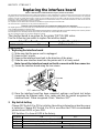
1. Replacing the interface board
1 Make sure that the power cord is unplugged.
2 Remove the 2 screws.
3 Remove the interface board unit in the direction of the arrow.
4 Slide the new interface board into the printer until it is firmly seated.
Note: Insert the interface board so that it connects with the connector.
5 Secure the interface board using the two screws.
6 Once the interface board has been connected, perform a self-print test before
connecting the Ethernet cable. Also, make sure that the printer recognizes the
interface board. When recognized: Prints “Interface: NIC”.
2. Dip Switch Setting
Change DIP Switch 2 to ON to initialize the setting information when the power
is turned on. Change DIP Switch 4 to ON to use either the STAR recommended
printer driver OPOS or Java POS.
DIP Switches 1 to 4 are all OFF at the factory.
80871271 IFTBD
-
NIC7
LED
Screws
DIP switch
DipSwitch ON OFF
1 Fixed at OFF
2 Initialize of settin
g
information
3 Fixed at OFF
4 Multi-session Single-session

3. LED Display
Green : Lights when other party connection is recognized as 10BASE-T.
Orange : Lights when packets are received.
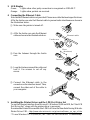
4. Connecting the Ethernet Cable
Note that the Ethernet cable is not provided. Please use a cable that meets specifications.
Affix the ferrite core onto the Ethernet cable to prevent radio interference as shown in
the illustration below.
1 Make sure the printer is turned off.
2 Affix the ferrite core onto the Ethernet
cable as shown in the illustration below.
3 Pass the fastener through the ferrite
core.
4 Loop the fastener around the cable and
lock it. Use scissors to cut off any
excess.
5 Connect the Ethernet cable to the
connector on the interface board. Then,
connect the other end of the cable to
your computer.
5. Installing the Printer Driver and the LPR Port Driver Set
To use the Ethernet interface from Microsoft’s Windows 95/98 and ME, the“Star LPR
Port Driver Set” along with the printer driver is necessary.
Download the Printer Driver and the Star LPR Port Driver Set from thefollowing Web site.
Printer Driver URL : http://www.star-micronics.co.jp/service/frame_sp_spr_e.htm
* To use Windows NT 4.0/2000/XP, the “Star LPR Port Driver Set” is unnecessary.
10cm
(
Maximum
)
Fastener
Ferrite core
Ethernet cable
-
 1
1
-
 2
2


Star Micronics TSP700 Series Replacement
- Taper
- Replacement
- Ce manuel convient également à
dans d''autres langues
- English: Star Micronics TSP700 Series
Documents connexes
-
Star Micronics TSP700 Series Replacement
-
Star Micronics TSP1000 Series Manuel utilisateur
-
-
-
-
-
-
-
-
Star Micronics star tsp700 Manuel utilisateur