JB F6-BOOST Refrigerant Recovey Unit Manuel utilisateur
- Taper
- Manuel utilisateur

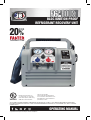
OPERATING MANUAL
BLDC IGNITION-PROOF
REFRIGERANT RECOVERY UNIT
Evaluated for performance in
accordance with Sec. 608 of the
Clean Air Act (Feb 29, 1996) using
AHRI-740-2016 test methods.
THIS EQUIPMENT HAS BEEN VERIFIED BY UNDERWRITERS LABORATORIES INC. TO MEET U.S. EPA’S MINIMUM REQUIREMENTS FOR RECOVERY
EQUIPMENT INTENDED FOR USE WITH ALL SYSTEMS CONTAINING REFRIGERANTS FROM AHRI-740-2016 CATEGORIES III, IV, AND V. UL CONTROL
NUMBER SA45599.
ISA 12.12.01:2016 Ed.7
Nonincendive Electrical Equipment
For Use In Class I and II, Division 2 and
Class III, Divisions 1 And 2 Hazardous
(Classified) Locations
VERIFIED
THAN COMPETITION*
OVER
20
%
*Speed based on vapor recovery for certain refrigerants.

2
JB INDUSTRIES • F6-BOOST Operating Manual • 630.851.9444 • [email protected]
Thank you for selecting the F6-BOOST Refrigerant Recovery Unit. The F6-BOOST Refrigerant Recovery
Unit provides users over 20% faster recovery rates than competitor models. The unique 2-cylinder, oilless
compressor and long-lasting pistons are contained in a light-weight, ergonomically designed, easy-to-
use unit. The F6-BOOST gives the user fast and reliable refrigerant recovery of ARHI groups III, IV, and V
refrigerants.
Only qualified personnel trained in the handling of refrigerants should operate this piece of equipment.
Working with refrigerants under pressures presents numerous safety risks and hazardous.
Read and understand this operator’s manual and all safety materials before using. Failure to
properly use this unit can result in personal injury and/or equipment damage.
TABLE OF CONTENTS
Box Contents . . . . . . . . . . . . . . . . . . . . . . . . . . . . 2
F6-BOOST Features . . . . . . . . . . . . . . . . . . . . . . . . 2
F6-BOOST General Safety Instructions . . . . . . . . . . . . . . . 3
F6-BOOST Flammable Refrigerant Safety Instructions . . . . . . . 4
F6-BOOST Refrigerant Storage Cylinder Safety. . . . . . . . . . . 5
F6-BOOST Specifications. . . . . . . . . . . . . . . . . . . . . . 6
F6-BOOST Unit Layout . . . . . . . . . . . . . . . . . . . . . . . 7
F6-BOOST Unit Operation . . . . . . . . . . . . . . . . . . . . . 8
Direct Recovery . . . . . . . . . . . . . . . . . . . . . . . . . 8
Purge Procedure. . . . . . . . . . . . . . . . . . . . . . . . . 9
Liquid Push-Pull Recovery . . . . . . . . . . . . . . . . . . . 9
F6-BOOST Troubleshooing. . . . . . . . . . . . . . . . . . . . .10
F6-BOOST Electrical and Plumbing Diagrams . . . . . . . . . . .11
F6-BOOST Part Numbers. . . . . . . . . . . . . . . . . . . . . .11
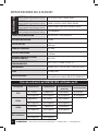
F6-BOOST FEATURES
• Dual voltage (100-240VAC 50/60Hz)
• Powerful 1.25 HP BLDC (Brushless DC) motor driven oil-less compressor
• Ignition-proof design tested and approved to ISA 12.12.01:2016 Ed.7
• High air flow fan with a micro-channel condenser to keep the unit running cool
• Variable speed motor (based on load)
• 2-piece, oilless piston seal design with long-lasting, durable elastomer, easy-to-replace piston seals
• Non-pressurized vented crank case (prevents refrigerant from damaging bearings or seals)
• Built in purge functionality (self clearing or pump down) to prevent cross contamination
• High pressure 550 PSIG cutout switch
• Easy-to-use interface with 2" high/low gauges
• Auto shut-off when recovery is complete
• Status Indicator light
• Optional stainless steel interior model for medical related industries
• Compact light-weight 24lb unit with robust, high-impact, injection-molded case
• Recessed folding handle with rubber grip and padded shoulder strap
• 10’ locking power cable and velcro cord wrap
• 1 year OTC; 2-year repair and return warranty
BOX CONTENTS
• F6-BOOST Refrigerant
Recovery Unit
• 10' Locking power cord 115v
• Padded shoulder strap
• Operation Manual

3
JB INDUSTRIES • F6-BOOST Operating Manual • 630.851.9444 • [email protected]
F6-BOOST GENERAL SAFETY INSTRUCTIONS
Please read, follow and understand the contents of this entire manual, with special attention given to Danger,
Warning and Caution statements.
FOR USE BY PROFESSIONALLY TRAINED AND CERTIFIED OPERATORS ONLY. MOST STATES,
COUNTRIES, ETC., MAY REQUIRE USER TO BE LICENSED. PLEASE CHECK WITH YOUR
LOCAL GOVERNMENT AGENCY.
DANGER: The recovery tank used with this contains liquid refrigerant. Overfilling recovery tank may cause
a violent rupture resulting in severe injury or even death. As a minimum, please use a
scale to continuously monitor recovery tank weight.
DANGER: EXPLOSION RISK! This equipment can be used in Class I and II, Division 2 and Class III,
Divisions 1 And 2 Hazardous (Classified) Locations. Technicians should be fully trained on
services in this hazardous location.
DANGER: ELECTRICAL SHOCK HAZARD: Always disconnect power source when servicing this
equipment.
WARNING: Do not use equipment in the vicinity of spilled or open containers of gasoline or other
flammable substances.
WARNING: All hoses may contain liquid refrigerant under pressure. Contact with refrigerant may cause
frostbite or other related injuries. Wear proper personal protective equipment such as safety
goggles and gloves. When disconnecting any hose, please use extreme caution.
WARNING: TO REDUCE RISK OF FIRE: Avoid use of an extension cord because extension cord may
overheat. If you must use an extension cord, use 10 awg minimum.
WARNING: Avoid breathing refrigerant vapors and lubricant vapor or mist. Breathing high concentration
levels may cause heart arrhythmia, loss of consciousness, or even cause suffocation. Exposure
may irritate eyes, nose, throat and skin. Please read manufacturer’s Material Safety Data Sheet
for further safety information on refrigerants and lubricants.
WARNING: Make certain all safety devices are functioning properly before operating equipment.
CAUTION: To avoid cross contamination of refrigerant and potential leakage to the atmosphere, proper
hoses and fittings should be used and checked for damage.
CAUTION: To avoid overfilling refrigerant tank, read and follow manufacturer’s recommended filling
instructions for refrigerant being recovered.
CAUTION: This equipment is intended for use of one refrigerant at a time. Mixing of different refrigerants
will cause your recovered supply of refrigerant to become contaminated.
Note: It is very expensive to destroy mixed or damaged refrigerants.

4
JB INDUSTRIES • F6-BOOST Operating Manual • 630.851.9444 • [email protected]
F6-BOOST FLAMMABLE REFRIGERANT
SAFETY INSTRUCTIONS
The following are additional safety recommendations when servicing HVAC&R equipment containing
flammable refrigerants. These instructions do not replace existing occupational hazardous procedures or
other local, state and/or federal agency regulations.
Technicians working on HVAC&R systems with flammable refrigerants should have detailed knowledge and
skills in handling flammable refrigerants, personal protective equipment, refrigerant leak prevention, handling
of cylinders, leak detection and monitoring, and proper disposal of contaminated refrigerants. Additional
knowledge of legislation, regulations, and standards relating to flammable refrigerants may also be required.
Check your local occupational safety codes.
The area of service should be marked as Temporary Hazardous or Flammable Zone. This will be a 3 meter
(10 feet) perimeter around the HVAC&R equipment being serviced. No smoking signs or other hazardous
zone signs should be posted. Local supervisor should be notified of the hazardous zone’s existence.
The following are recommended practices when servicing flammable HVAC&R equipment:
• A flammable gas detector should be used to monitor the air in the Temporary Flammable Zone.
• A dry powder or CO2 fire extinguisher must be available at the service location.
• An ignition proof ventilation fan should be used to provide a minimum of 5 air changeovers per hour.
• Ensure the HVAC&R equipment has been disconnected from electrical service.
• All potential ignition sources within the Temporary Flammable Zone must be disabled.
• When connecting service equipment such as vacuum pumps, scales, recovery units, etc. to a power
source, the connection must be made outside the Temporary Hazardous Zone perimeter.
• A grounding strap must be used between the recovery unit’s metal INLET or OUTLET port and recovery
tank’s unpainted metal fitting. The grounding strap is used to dissipate any static electricity build up that
can occur, especially during liquid recovery.
• Once the recovery process of the flammable refrigerant is complete, the HVAC&R system should be purged
with 100% Nitrogen. Do not use air.
DANGER - EXPLOSION RISK: Do not mix flammable refrigerants with air. All precautions
must be taken to eliminate the mixing of air with flammable refrigerants, including
monitoring the recovery cylinder of air or oxygen content.

5
JB INDUSTRIES • F6-BOOST Operating Manual • 630.851.9444 • [email protected]
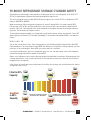
F6-BOOST REFRIGERANT STORAGE CYLINDER SAFETY
Check with your federal and/or state regulations on the proper vessel to store refrigerant. In the USA, DOT
CFR 40 is required when filling and transporting refrigerant storage vessels.
This unit is designed to be used with 400 PSIG rated storage vessels. In the USA, this is denoted by a DOT
rating of 4ABA400 or 4BW400.
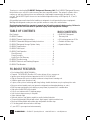
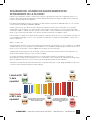
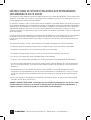
When recovering or filling a refrigerant storage vessel, never fill beyond 80% of its water capacity (WC).
Filling a tank at 70F to 90% and then putting it in a hot service van will cause the liquid to expand until it
becomes 100% full. The hydrostatic force of the refrigerant could rupture the tank causing rapid venting or
explosion. See illustration in Diagram 1 below.
To calculate the maximum weight of a storage tank you will need to get two ratings from the tank. One is WC
(water capacity) and the other is TW (empty tank weight). The maximum tank weight (MTW) is calculated as
follows:
MTW=.8 x WC + TW
Turn on the scale and tare to Zero. Place storage tank on scale. Read the weight. Compare that to the MTW
calculated above. If the scale weight is below MTW, the difference is the amount of storage capacity you have
in the tank. If the scale weight is above MTW, you have a tank that is overfilled.
If an overfill condition does exist on a storage tank, place in a cool area and transfer some of the refrigerant
into another storage tank until the weight is below MTW.
Always use a calibrated scale to monitor the total weight of the tank when recovering or filling refrigerant into
a storage tank. Devices such as tank overfill floats should stop the recovery unit, but do not stop the flow of
refrigerant to the storage tank.
If the scale or an overfill device does detect tank full condition, the recovery unit should be turned off and the
storage tank valves closed.
80%
60 ˚F
85%
90˚ F
90%
120˚ F
90%
60˚ F
95%
90 ˚F
100%
Danger:
Tank Rupture
120 ˚F
Filled to 80%
Capacity
Overfilled
to 90%
Capacity
Overfilled storage containers may explode due
to liquid refrigerant expanding when heated.
Transportation of refrigerant storage tanks
more than 80% full is a DOT violation.

6
JB INDUSTRIES • F6-BOOST Operating Manual • 630.851.9444 • [email protected]
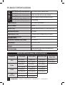
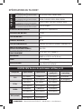
F6-BOOST SPECIFICATIONS
AHRI740 Class III
(120 - 169 PSIG @ 105°F Liquid Saturation) R12, R134a, R401C, R406A, R500
AHRI740 Class VI
(170 - 269 PSIG @ 105°F Liquid Saturation)
R22, R401A/B, R402B,R407C/D/E/F, R408A,
R409A, R411A/B, R412A, R502, R509A
AHRI740 Class V
(270 - 355 PSIG @ 105°F Liquid Saturation) R402A, R404A, R407A/B, R410A/B, R507A
AHRI740 Class V, Type A2L pending
(270 - 355 PSIG @ 105°F Liquid Saturation) R-32 pending
POWER SUPPLY 100-240VAC 1ph 50/60Hz
MOTOR POWER 1.25 HP
MOTOR TYPE Variable Speed Brushless DC, 1200-3000 RPM
MAXIMUM CURRENT 13.0 amps
COMPRESSOR TYPE 2 Cylinder Oilless Reciprocating, Air Cooled
HIGH PRESSURE CUTOUT
(MANUAL RESET) 550 PSIG
OPERATING TEMPERATURE RANGE 32°F to 120°F
DIMENSIONS 14.5" x 9.5" x 12.0"
WEIGHT 24lb
CERTIFICATIONS Ignition-proof design tested and approved to
ISA 12.12.01:2016 Ed.7
REFRIGERANTS
ARHI740-2016 Performance Data certified by UL
Refrigerant Direct Vapor Direct Liquid Push-Pull Liquid High Temp.
Vapor Rate
R22 0.77 lb/min 12.40 lb/min 13.43 lb/min 0.75 lb/min
(0.35 kg/min) (5.61 kg/min) (6.08 kg/min) (0.34 kg/min)
R134a 0.68 lb/min 9.97 lb/min 10.11 lb/min
(0.31 kg/min) (4.53 kg/min) (4.59 kg/min)
R410A 0.76 lb/min 11.08 lb/min 15.34 lb/min
(0.34 kg/min) (5.03 kg/min) (6.96 kg/min)
R32
(estimate)
0.76 lb/min 11.08 lb/min
(0.35 kg/min) (5.03 kg/min)

7
JB INDUSTRIES • F6-BOOST Operating Manual • 630.851.9444 • [email protected]
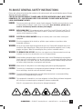
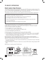
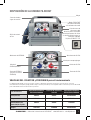
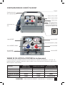
F6-BOOST UNIT LAYOUT
MANIFOLD VALVES and POSITIONS for operation
The unit is designed with a manifold containing 3 ball valves for Recovery, Liquid Push-Pull, and Purge
(Self-Clearing or Pump Down) operations. The following table shows the proper position for each ball
valve vs. the Operation.
Operation INLET/PURGE
Valve Position OUTLET
Valve Position RECOVER/PURGE
Valve Position
Recovery OPEN OPEN RECOVER
Purge PURGE OPEN PURGE
Liquid Push-Pull OPEN OPEN PURGE
Off CLOSE CLOSE RECOVER
INLET Gauge
Shoulder Strap
Connection Location
Air Intake Grill
INLET/PURGE Valve
INLET Port
(Contains INLET filter)
OUTLET Gauge
Handle
STOP/START Button
Status Indicator Light
Velcro Cord Wrap
Knock-out location
for optional tank
overflow switch
(sold separately)
Part no. F6-BOOST-TOC
Fan Exhaust
Recover/Purge Valve
OUTLET Valve
OUTLET Port

8
JB INDUSTRIES • F6-BOOST Operating Manual • 630.851.9444 • [email protected]
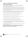
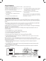
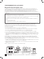
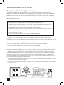
F6-BOOST OPERATION
Direct Liquid or Vapor Recovery
The following are additional safety recommendations when servicing HVAC&R equipment containing refrigerant. This
is the most common method of recovery operation for HVAC&R systems containing less than 20 kg of refrigerant. For
larger systems PUSH-PULL LIQUID RECOVERY method can help speed up the process.
The following are step by step instructions on how to operate the recovery unit in Direct Liquid or Vapor Recovery.
The following is recommended to maximize recovery rates:
A. Use the shortest length of 3/8” ID refrigeration hose on the suction side of the unit.
B. If the refrigerant is clean, remove all suction side filters, screens, etc.
C. Remove all Schrader type valve cores and any valve depressors from the hoses and service valves.
D. Use an evacuated DOT tank.
E. If the unit trips off on High Pressure, change the recovery cylinder.
1. Place a Refrigerant Storage Tank on a scale to determine the current weight of the tank.
DANGER: Make sure the storage tank has enough capacity for the recovery process. See Page 5 for refrigerant
capacity and refrigerant storage tank safety guidelines.
2. Connect refrigerant hoses as shown in diagram below.
3. Turn the OUTLET valve to OPEN. Open Refrigerant Storage tank valve.
4. Turn the RECOVER/PURGE to RECOVER position
5. Plug in the unit into 115v or 230v power source. The Indicator LED will flash GREEN.
6. Push the START button. The Indicator LED will turn solid green. Once the unit’s compressor starts turn the INLET
valve to the OPEN position. If liquid refrigerant is being recovered and a slugging noise is heard, turn the INLET
valve into the LIQUID region until the slugging noise subsides.
Monitor the electronic scale for weight gained during recovery and ensure the tank is not being overfilled. If
approaching tank full conditions, push the Power Switch to OFF position and close tank valve. Replace tank with an
empty one. Push the Power Switch to ON position to resume recovery operation.
7. The unit will automatically shut off after 2 minutes when the INLET pressure drops below 10" hg vac. The Indicator
LED will turn solid YELLOW.
8. Monitor the Inlet gauge for a few minutes, if the pressure rises above 0 PSIG restart the unit by pushing the START
button.
When Recovery is complete, proceed to Purge Procedure.
Service Port
Service Port
OUTLET
INLET
Vapor
Valve
Electronic Scale
Storage
Tank
HVAC
SYSTEM

9
JB INDUSTRIES • F6-BOOST Operating Manual • 630.851.9444 • [email protected]
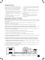
Purge Procedure
It is necessary to clear out the unit’s condenser of residual
refrigerants. The unit utilizes a purge or
self-clearing feature. Note: Failure to do this process will
lead to cross-contaminated refrigerant.
1. Once recovery is done, turn the RECOVER/PURGE valve to
the PURGE position
2. Push the START button. The Indicator LED will turn
solid GREEN.
3. Turn the INLET valve to the PURGE position
4. Monitor the INLET gauge.
5. The unit will automatically shut off after 2 minutes* when the
internal condenser pressures drops below 10" hg vacuum.
The Indicator LED will turn solid YELLOW.
6. Close all tank valves, hose valves and the unit’s valves.
Disconnect all hoses.
Purge is now complete. The unit is ready for the next refrigerant.
*Note: Purge can be manually stopped before the 2 minute timer
automatically turns off the unit.
Liquid Push-Pull Recovery
The LIQUID PUSH-PULL RECOVERY operation is used on large HVAC&R Systems containing more than 20KG of
liquid refrigerant. The unit must have an access valve that is located in the part of the system were liquid refrigerant is
present.
The following are step by step instructions on how to operate the recovery unit in LIQUID PUSH-PULL RECOVERY.
1. Place a Refrigerant Storage Tank on a scale to determine the current weight of the tank.
DANGER: Make sure the storage tank has enough capacity to recover the refrigerants. See Page 5 for Tank Capacity
and safety issues on refrigerant storage tanks.
WARNING: Liquid recovery rates can be very fast. Overfilling a tank can happen quite quickly if the unit is not
monitored properly.
2. Connect refrigerant hoses as shown in diagram below.
3. Turn the OUTLET valve to OPEN. Open Refrigerant Storage tank valve.
4. Turn the RECOVER/PURGE to PURGE position
5. Plug in the unit into 115v or 230v power source. The Indicator LED will flash GREEN.
6. Push the START button. The Indicator LED will turn solid GREEN. Once the unit’s compressor starts, turn the
INLET valve to the OPEN position.
Monitor the electronic scale for weight gained during recovery and ensure the tank is not being overfilled. If
approaching tank full conditions, push STOP button and close tank valve. Replace tank with empty one. Push START
to resume recovery operation.
7. Monitor the scale to see if liquid refrigerant is no longer being pushed into the refrigerant storage tank.
Close Tank Vapor Valve.
8. Once the INLET pressure drops below 10” hg vac, the unit will automatically shut off after 2 minutes and the
Indicator LED will turn solid YELLOW.
LIQUID PUSH-PULL Recovery is now complete; proceed to Direct Vapor Recovery on page 8 to complete the
recovery process.
Electronic Scale
Storage
Tank
Liquid Service Port
Vapor Service Port
OUTLET
INLET
Vapor
Valve
Liquid
Valve
HVAC
SYSTEM

10
JB INDUSTRIES • F6-BOOST Operating Manual • 630.851.9444 • [email protected]
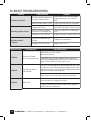
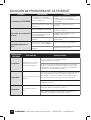
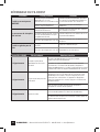
F6-BOOST TROUBLESHOOTING
Problem Possible Cause Solution
Unit will not turn ON
Unit not properly plugged in or
no power at power source
Check power cord to ensure properly
plugged into power source and IEC
inlet
Defective Power Switch or PCB Replace defective electrical component
Recovery process is slow
Plugged INLET Filter Check INLET port filter, Clean or replace
Valve core on system being
recovered not fully depressed Check core depressor on connecting
hoses
Compressor seals are worn Rebuild compressor, replace piston seal
Unit does not pull
a vacuum
Loose hose connections on
IN Side Tighten hose connections
Compressor seals are worn Replace piston seals
RED LED Code Fault Indicated Possible Solution
2 Flashes Optional Tank Overfill
Sensor has been activated
Tank overfill sensor has activated.
Replace recovery tank.
Tank overfill sensor cord not connected. Either connect to a
recovery tank equipped with overfill sensor, or install a shorting
plug on the end of the Tank Overfill Sensor cord.
3 Flashes High Pressure Swich as
been activated
Pressure on the discharge of the unit exceeded 550 PSIG. Check
to make sure all valves in the discharge pathway are open. Once
corrected, the pressure switch will reset. If equipped with manual
high pressure switch, push reset button.
Excessive pressure in recovery tank. Replace recovery tank.
4 Flashes Motor Fault
Let cool down for 5-10 minutes and restart.
Compressor Mechanism is jammed. Repair will be required to
fix the compressor mechanism.

11
JB INDUSTRIES • F6-BOOST Operating Manual • 630.851.9444 • [email protected]
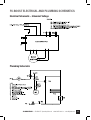
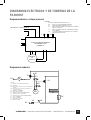
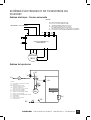
F6-BOOST ELECTRICAL AND PLUMBING SCHEMATICS
Electrical Schematic – Universal Voltage
Plumbing Schematic

12 JB INDUSTRIES • F6-BOOST Operating Manual • 630.851.9444 • [email protected]
0821
JB INDUSTRIES
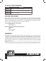
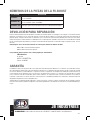
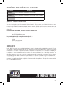
F6-BOOST PART NUMBERS
RETURN FOR REPAIR
Every effort has been made to provide reliable, superior quality products. However, in the event your instrument
requires repair, please contact JB Customer Service Department to obtain a Return Goods Authorization (RGA)
number. Ensure that all returned products are packed to avoid any damage in shipment. Paperwork should be
placed in a separate plastic bag and should include JB’s assigned RGA number, a description of the problem
and any customer assigned repair or purchase order number, if applicable.
Contact Customer Service for RGA number:
800.323.0811 Toll
800.552.5593 Toll Fax
Products should be shipped with freight prepaid to:
JB Industries
RGA#_________
601 N. Farnsworth Ave.
Aurora, IL 60505
WARRANTY
The F6-BOOST is warrantied against defects in materials and workmanship for 2 years from date of purchase.
1 year OTC and 2- year repair and return warranty. JB products are guaranteed when used in accordance with
our guidelines and recommendations. Warranty is limited to the repair, replacement, or credit at invoice price,
(our option) of products which in our opinion are defective due to workmanship and/or materials. In no case
will we allow charges for labor, expense or consequential damage. Repairs performed on items out of warranty
will be invoiced on a nominal basis; contact wholesaler for details. Additional product information available
online at www.jbind.com.
WARNING: This product can expose you to chemicals including lead which are known to the State of California to
cause cancer and birth defects or other reproductive harm. For more information go to www.P65Warnings.ca.gov.
PART NO. DESCRIPTION
F6-BOOST BLDC Ignition-Proof Refrigerant Recovery Unit
F6-BOOST-SS BLDC Ignition-Proof Refrigerant Recovery Unit (Stainless Steel)
F6-BOOST-TOC Optional tank overflow switch

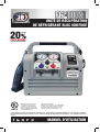
MANUAL DE INSTRUCCIONES
UNIDAD DE RECUPERACIÓN DE REFRIGERANTE A PRUEBA
DE IGNICIÓN CON MOTOR DC SIN ESCOBILLAS
Rendimiento evaluado de acuerdo con la
Sección 608 de la Ley de Aire Limpio (29
de febrero de 1996) mediante el uso de
métodos de prueba AHRI-740-2016.
ESTE EQUIPO CUENTA CON LA VERIFICACIÓN DE UNDERWRITERS LABORATORIES INC. PORQUE CUMPLE CON LOS REQUISITOS MÍNIMOS DE LA AGENCIA DE
PROTECCIÓN AMBIENTAL (EPA) PARA LOS EQUIPOS DE RECUPERACIÓN DISEÑADOS PARA SU USO CON TODOS LOS SISTEMAS QUE CONTIENEN REFRIGERANTES DE
AHRI-740-2016; CATEGORÍAS III, IV Y V. NÚMERO DE CONTROL SA45599.
Norma ISA 12.12.01:2016 Ed.7
Equipo eléctrico no incendiario para uso en
lugares peligrosos (clasificados) de claseI y II,
división2 y claseIII, divisiones1 y 2.
VERIFICADO
QUE LA DE LA COMPETENCIA*
MÁS DE UN
20
%
MÁS RÁPIDA
*Velocidad basada en la recuperación de vapor para ciertos refrigerantes.

2
JB INDUSTRIES • Manual de instrucciones de la F6-BOOST • 630.851.9444 • [email protected]
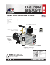
Gracias por elegir la unidad de recuperación de refrigerante F6-BOOST. La unidad de recuperación de refrigerante F6-
BOOST brinda a los usuarios una velocidad de recuperación un 20% superior que los modelos de la competencia. El compresor
exclusivo sin aceite de 2cilindros y los pistones de larga duración se encuentran en una unidad fácil de usar, de diseño
ergonómico y liviana. La F6-BOOST le brinda al usuario una recuperación de refrigerante rápida y confiable de refrigerantes de
los grupos III, IV y V del Instituto de Aire Acondicionado, Calefacción y Refrigeración (ARHI).
Solo personal calificado entrenado en la manipulación de refrigerantes debe hacer funcionar este equipo. Trabajar con
refrigerantes bajo presión presenta numerosos riesgos de seguridad y peligros.
Lea y comprenda este manual del operador y todos los materiales de seguridad antes de usar este equipo. No usar
esta unidad correctamente puede provocar lesiones personales o daños al equipo.
ÍNDICE
Contenido de la caja . . . . . . . . . . . . . . . . . . . . . . . . . . . . . . . 2
Características de la F6-BOOST . . . . . . . . . . . . . . . . . . . . . . . . . 2
Instrucciones generales de seguridad de la F6-BOOST. . . . . . . . . . . . . . 3
Instrucciones de seguridad del refrigerante inflamable de la F6-BOOST . . . . . 4
Seguridad del cilindro de almacenamiento de refrigerante de la F6-BOOST . . . 5
Especificaciones de la F6-BOOST . . . . . . . . . . . . . . . . . . . . . . . . 6
Disposición de la unidad F6-BOOST . . . . . . . . . . . . . . . . . . . . . . . 7
Funcionamiento de la unidad F6-BOOST. . . . . . . . . . . . . . . . . . . . . 8
Recuperación directa . . . . . . . . . . . . . . . . . . . . . . . . . . . . . 8
Procedimiento de purga. . . . . . . . . . . . . . . . . . . . . . . . . . . . 9
Recuperación de líquido por succión y retroalimentación (Push-Pull) . . . 9
Solución de problemas de la F6-BOOST . . . . . . . . . . . . . . . . . . . . . 10
Diagramas eléctricos y de tuberías de la F6-BOOST . . . . . . . . . . . . . . . 11
Números de las piezas de la F6-BOOST . . . . . . . . . . . . . . . . . . . . . 11
CARACTERÍSTICAS DE LA F6-BOOST
• Doble voltaje (100-240V AC 50/60Hz).
• Compresor potente sin aceite con motor DC sin escobillas (BLDC) de 1,25HP.
• Diseño a prueba de ignición probado y aprobado de acuerdo con la norma ISA 12.12.01:2016 Ed.7.
• Ventilador de flujo de aire elevado con un condensador de microcanales para mantener la unidad fría durante el funcionamiento.
• Motor de velocidad variable (basado en la carga).
• Diseño de juntas de pistón sin aceite de 2piezas con juntas de pistón de elastómero duraderas y fáciles de reemplazar.
• Cárter con ventilación no presurizado (evita que el refrigerante dañe los rodamientos o las juntas).
• Función de purga incorporada (autodescarga o vaciado por bombeo) para evitar la contaminación cruzada.
• Presostato de alta presión 550PSIG.
• Interfaz fácil de usar con manómetros de alta y baja presión de 2".
• Apagado automático cuando se completa la recuperación.
• Luz indicadora de estado.
• Modelo con interior de acero inoxidable opcional para industrias relacionadas a la medicina.
• Unidad liviana y compacta de 10,8kg (24lb) con carcasa robusta moldeada por inyección de alto impacto.
• Mango plegable encastrado con agarre de goma y correa de hombro acolchada.
• Cable de alimentación con bloqueo de 10’ y cinta de amarre de Velcro para cable.
• Garantía de 1año de pago al contado y de 2años por reparación o devolución
CONTENIDO DE LA
CAJA
• Unidad de recuperación de
refrigerante F6-BOOST.
• Cable de alimentación con bloqueo de
10' y 115V.
• Correa de hombro acolchada.
• Manual de instrucciones.

3
JB INDUSTRIES • Manual de instrucciones de la F6-BOOST • 630.851.9444 • [email protected]
INSTRUCCIONES GENERALES DE SEGURIDAD DE LA F6-BOOST
Lea, siga y comprenda el contenido de todo este manual y preste especial atención a los enunciados de peligro, advertencia y
precaución.
PARA USO EXCLUSIVO DE OPERARIOS CERTIFICADOS Y PROFESIONALMENTE ENTRENADOS. EN LA MAYORÍA
DE LOS ESTADOS, PAÍSES, ETC. SE PUEDE REQUERIR QUE EL USUARIO TENGA UNA LICENCIA PARA OPERAR
EL EQUIPO. VERIFIQUE CON EL ORGANISMO GUBERNAMENTAL LOCAL.
PELIGRO: El tanque de recuperación que se usa con esto contiene refrigerante líquido. El llenado en exceso del
tanque de recuperación puede causar una ruptura violenta que resulte en lesiones graves o incluso la
muerte. Como mínimo, use una balanza para controlar continuamente el peso del tanque
de recuperación.
PELIGRO: ¡RIESGO DE EXPLOSIÓN! Este equipo se puede usar en lugares peligrosos (clasificados) de claseI
y II, división2 y claseIII, divisiones1 y 2. Los técnicos deben estar completamente capacitados en
hacer trabajos de mantenimiento en este lugar peligroso.
PELIGRO: RIESGO DE DESCARGA ELÉCTRICA: Desconecte siempre la fuente de alimentación cuando haga
trabajos de mantenimiento en este equipo.
ADVERTENCIA: No use el equipo cerca de contenedores de gasolina abiertos o derramados ni de otras sustancias
inflamables.
ADVERTENCIA: Todas las mangueras pueden contener refrigerante líquido bajo presión. El contacto con el
refrigerante puede causar congelación u otras lesiones relacionadas. Use un equipo de protección
personal apropiado, como gafas de seguridad y guantes. Cuando desconecte alguna manguera, sea
extremadamente cuidadoso.
ADVERTENCIA: PARA REDUCIR EL RIESGO DE INCENDIO: Evite usar un cable de extensión porque el cable de
extensión puede sobrecalentarse. Si debe usar un cable de extensión, use uno de 10AWG, como
mínimo.
ADVERTENCIA: Evite respirar los vapores de refrigerante y el vapor o el vaho del lubricante. Respirar niveles altos
de concentración puede causar arritmias cardíacas, pérdida del conocimiento o incluso sofocación.
La exposición puede irritar los ojos, la nariz, la garganta y la piel. Lea la Hoja de datos de seguridad
de los materiales del fabricante para obtener más información de seguridad sobre refrigerantes y
lubricantes.
ADVERTENCIA: Asegúrese de que todos los dispositivos de seguridad estén funcionando correctamente antes de
hacer funcionar el equipo.
PRECAUCIÓN: Para evitar la contaminación cruzada del refrigerante y una posible fuga a la atmósfera, se deben
usar mangueras y accesorios apropiados y se debe verificar que no estén dañados.
PRECAUCIÓN: Para evitar el llenado en exceso del tanque de refrigerante, lea y siga las instrucciones de llenado que
recomienda el fabricante para el refrigerante que se está recuperando.
PRECAUCIÓN: Este equipo está diseñado para usar un refrigerante a la vez. Mezclar refrigerantes diferentes puede
hacer que el suministro de refrigerante recuperado se contamine.
Nota: Es muy costoso destruir refrigerantes mezclados o dañados.

4
JB INDUSTRIES • Manual de instrucciones de la F6-BOOST • 630.851.9444 • [email protected]
INSTRUCCIONES DE SEGURIDAD DEL REFRIGERANTE
INFLAMABLE DE LA F6-BOOST
Las siguientes son recomendaciones de seguridad adicionales para cuando se realizan las tareas de mantenimiento de
equipos de calefacción, ventilación, aire acondicionado y refrigeración (HVAC&R) que contienen refrigerantes inflamables. Estas
instrucciones no reemplazan los procedimientos de riesgos laborales ni otros reglamentos de organismos federales, estatales ni
locales.
Los técnicos que trabajen en sistemas de HVAC&R con refrigerantes inflamables deben tener conocimientos detallados y
habilidades en el manejo de refrigerantes inflamables, equipo de protección personal, prevención de fugas de refrigerante,
manejo de cilindros, detección y control de fugas, y eliminación adecuada de refrigerantes contaminados. Es posible que
también se requiera conocimiento adicional de las leyes, reglamentos y estándares relacionados con refrigerantes inflamables.
Verifique los códigos de seguridad laboral locales.
El área de mantenimiento se debe marcar como zona temporalmente peligrosa o inflamable. Esta área consistirá en un
perímetro de 3metros (10pies) alrededor del equipo de HVAC&R al que se le está haciendo el mantenimiento. Se deben colocar
letreros de prohibido fumar u otros letreros de zona peligrosa. Se debe informar al supervisor local de la existencia de la zona
peligrosa.
Las siguientes son prácticas recomendadas cuando se hace el mantenimiento de un equipo de HVAC&R inflamable:
• Se debe usar un detector de gases inflamables para controlar el aire en la zona temporalmente inflamable.
• En el lugar donde se realizan las tareas de mantenimiento, debe haber un extintor de polvo seco o de CO2.
• Se debe usar un ventilador de ventilación a prueba de ignición para proporcionar un mínimo de 5cambios de aire por hora.
• Asegúrese de que el equipo de HVAC&R se haya desconectado del servicio eléctrico.
• Se deben inhabilitar todas las posibles fuentes de ignición dentro de la zona temporalmente inflamable.
• Cuando se conecten equipos de mantenimiento, como bombas de vacío, balanzas, unidades de recuperación, etc., a una
fuente de alimentación, la conexión se debe hacer fuera del perímetro de la zona temporalmente peligrosa.
• Se debe usar una cinta de conexión a tierra entre el puerto metálico de ENTRADA o de SALIDA de la unidad de recuperación
y el accesorio metálico sin pintar del tanque de recuperación. La cinta de conexión a tierra se usa para disipar cualquier
acumulación de electricidad estática que pueda ocurrir, especialmente durante la recuperación del líquido.
• Una vez que se complete el proceso de recuperación del refrigerante inflamable, el sistema de HVAC&R se debe purgar con
nitrógeno al 100%. No use aire.
PELIGRO. RIESGO DE EXPLOSIÓN: No mezcle refrigerantes inflamables con aire. Se deben tomar todas las
precauciones para eliminar la mezcla de aire con refrigerantes inflamables, lo que incluye controlar que el
cilindro de recuperación no tenga contenido de aire ni de oxígeno.

5
JB INDUSTRIES • Manual de instrucciones de la F6-BOOST • 630.851.9444 • [email protected]
SEGURIDAD DEL CILINDRO DE ALMACENAMIENTO DE
REFRIGERANTE DE LA F6-BOOST
Verifique en los reglamentos federales o estatales qué recipiente es apropiado para almacenar el refrigerante. En EE.UU., se
requiere el Título40 del Código de Reglamentos Federales (CFR) del Departamento de Transporte (DOT) al llenar y transportar
recipientes de almacenamiento de refrigerante.
Esta unidad está diseñada para usarla con recipientes de almacenamiento clasificados de 400PSIG. En EE.UU., esto se indica
con una clasificación del DOT de 4ABA400 o 4BW400.
Cuando recupere o llene un recipiente de almacenamiento de refrigerante, nunca lo llene más del 80% de su capacidad
de agua (WC). Llenar un tanque a 21°C (70°F) al 90% y luego ponerlo en una camioneta con servicio de alta temperatura
causará que el líquido se expanda hasta que el tanque se llene al 100%. La fuerza hidrostática del refrigerante podría romper el
tanque, lo que causaría un vaciado rápido o una explosión. Consulte la ilustración en el diagrama1 abajo.
Para calcular el peso máximo de un tanque de almacenamiento, tendrá que obtener dos valores correspondientes al tanque. Uno
es la capacidad de agua (WC) y el otro es el peso del tanque vacío (TW). El peso máximo del tanque (MTW) se calcula como se
indica a continuación:
MTW=.8×WC+TW
Encienda la balanza y tárela a cero. Coloque el tanque de almacenamiento sobre la balanza. Lea el peso. Compárelo con el MTW
calculado arriba. Si el peso de la balanza es inferior al MTW, esa es la cantidad de capacidad de almacenamiento que tiene en el
tanque. Si el peso de la balanza es superior al MTW, tiene un tanque que está sobrellenado.
Si algún tanque de almacenamiento está sobrellenado, colóquelo en un área fría y transfiera una parte del refrigerante a otro
tanque de almacenamiento hasta que el peso sea inferior al MTW.
Use siempre una balanza calibrada para controlar el peso total del tanque cuando llene de refrigerante un tanque de
almacenamiento o cuando recupere refrigerante en este. Los dispositivos como los flotadores de sobrellenado del tanque deben
detener la unidad de recuperación, pero no detener el flujo de refrigerante al tanque de almacenamiento.
Si la balanza o un dispositivo de sobrellenado detecta una condición de tanque lleno, se debe apagar la unidad de recuperación
y se deben cerrar las válvulas del tanque de almacenamiento.
80 % 85 % 90 %
90 %
15,5 °C (60 °F)
95 % 100 %
Peligro:
Ruptura del
tanque
Llenado al 80
% de la
capacidad
Sobrellenado
al 90 % de la
capacidad Los contenedores de almacenamiento so-
brellenados pueden explotar debido a que el
refrigerante líquido se expande cuando se
calienta.
El transporte de tanques de almacenamiento de
refrigerante llenos con más del 80 % de su ca-
pacidad es una infracción al DOT.
15,5 °C (60 °F)
32,2 °C (90 °F)
32,2 °C (90 °F)
48,8 °C (120 °F)
48,8 °C (120 °F)

6
JB INDUSTRIES • Manual de instrucciones de la F6-BOOST • 630.851.9444 • [email protected]
ESPECIFICACIONES DE LA F6-BOOST
AHRI740 claseIII
(Saturación de líquidos a 120-169PSIG a 40,5°C [105°F]) R12, R134a, R401C, R406A, R500
AHRI740 claseVI
(Saturación de líquidos a 170-269PSIG a 40,5°C [105°F])
R22, R401A/B, R402B,R407C/D/E/F, R408A,
R409A, R411A/B, R412A, R502, R509A
AHRI740 claseV
(Saturación de líquidos a 270-355PSIG a 40,5°C [105°F]) R402A, R404A, R407A/B, R410A/B, R507A
AHRI740 claseV, tipo A2L pendiente
(Saturación de líquidos a 270-355PSIG a 40,5°C [105°F]) R-32 pendiente
FUENTE DE ALIMENTACIÓN 100-240V AC, 1 fase, 50/60Hz
POTENCIA DEL MOTOR 1,25HP
TIPO DE MOTOR DC sin escobillas de velocidad variable 1200-
3000rpm
CORRIENTE MÁXIMA 13,0amp.
TIPO DE COMPRESOR Refrigerado por aire, alternativo, sin aceite y de
2cilindros
APAGADO POR ALTA PRESIÓN
(REINICIO MANUAL) 550PSIG
RANGO DE TEMPERATURA DE
FUNCIONAMIENTO De 0°C (32°F) a 48,8°C (120°F)
DIMENSIONES 36,8cm (14,5”)×24cm (9,5”)×30,4cm (12,0”)
PESO 10,8kg (24lb)
CERTIFICACIONES Diseño a prueba de ignición probado y aprobado
de acuerdo con la norma ISA 12.12.01:2016 Ed.7
REFRIGERANTES
Datos de rendimiento del ARHI740-2016 certificados por UL
Refrigerante Vapor directo Líquido directo
Líquido de succión
y retroalimentación
(Push-Pull)
Velocidad del vapor
a alta temperatura
R22 0,77lb/min 12,40lb/min 13,43lb/min 0,75lb/min
(0,35kg/min) (5,63kg/min) (6,10kg/min) (0,34kg/min)
R134a 0,68lb/min 9,97lb/min 10,11lb/min
(0,31kg/min) (4,53kg/min) (4,59kg/min)
R410A 0,76lb/min 11,08lb/min 15,34lb/min
(0,34kg/min) (5,03kg/min) (6,96kg/min)
R32 (estimado) 0,76lb/min 11,08lb/min
(0,35kg/min) (5,03kg/min)

7
JB INDUSTRIES • Manual de instrucciones de la F6-BOOST • 630.851.9444 • [email protected]
DISPOSICIÓN DE LA UNIDAD F6-BOOST
VÁLVULAS DEL COLECTOR y POSICIONES para el funcionamiento
La unidad está diseñada con un colector que contiene 3válvulas de bola para operaciones de recuperación, succión y
retroalimentación de líquido y purga (autodescarga o vaciado por bombeo). En la siguiente tabla se muestra la posición adecuada
para cada válvula de bola en función de la operación.
Funcionamiento Posición de válvula en
ENTRADA/PURGAR
Posición de válvula en
SALIDA
Posición de válvula en
RECUPERAR/PURGAR
Recuperación ABRIR ABRIR RECUPERAR
Purgar PURGAR ABRIR PURGAR
Succión y
retroalimentación
(Push-Pull) de líquido
ABRIR ABRIR PURGAR
Apagar CERRAR CERRAR RECUPERAR
Manómetro de ENTRADA
Correa de hombro
Lugar de conexión
Rejilla de entrada
de aire
Válvula de
ENTRADA/PURGA
Puerto de ENTRADA
(contiene un filtro de
ENTRADA)
Manómetro de SALIDA
Mango
Botón STOP/START
(DETENER E INICIAR)
Luz indicadora de estado
Cinta de amarre de
Velcro para cable
Ubicación para el interruptor
opcional para protección contra
el sobrellenado del tanque (se
vende por separado)
N.º pieza F6-BOOST-TOC
Salida de aire
Válvula para recuperar/purgar
Válvula de SALIDA
Puerto de SALIDA

8
JB INDUSTRIES • Manual de instrucciones de la F6-BOOST • 630.851.9444 • [email protected]
FUNCIONAMIENTO DE LA F6-BOOST
Recuperación directa de líquido o vapor
Las siguientes son recomendaciones de seguridad adicionales para cuando se realizan las tareas de mantenimiento a los
equipos de HVAC&R que contienen refrigerantes inflamables. Este es el método más frecuente de operación de recuperación
para sistemas de HVAC&R que contienen menos de 20kg de refrigerante. Para sistemas más grandes, el método de
RECUPERACIÓN DE LÍQUIDO POR SUCCIÓN Y RETROALIMENTACIÓN (PUSH-PULL) puede ayudar a acelerar el proceso.
Las siguientes son instrucciones paso a paso sobre cómo hacer funcionar la unidad de recuperación en la recuperación directa
de líquido o vapor.
Para maximizar las tasas de recuperación, se recomienda lo siguiente:
A. Use la longitud más corta de la manguera de refrigeración de 3/8” de diámetro interior en el lado de succión de la unidad.
B. Si la refrigeración está limpia, quite todos los filtros, rejillas, etc. del lado de succión.
C. Quite todos los núcleos de las válvulas Schrader y todos los depresores de válvula de las mangueras y las válvulas de
servicio.
D. Use un tanque del DOT evacuado.
E. Si la unidad se detiene en alta presión, cambie el cilindro de recuperación.
1. Coloque un tanque de almacenamiento de refrigerante en una balanza para determinar el peso actual del tanque.
PELIGRO: Asegúrese de que el tanque de almacenamiento tenga la capacidad suficiente para realizar el proceso de
recuperación. Consulte la página5 para conocer la capacidad de refrigerante y las directivas de seguridad del tanque de
almacenamiento de refrigerante.
2. Conecte las mangueras de refrigerante como se muestra en el diagrama abajo.
3. Gire la válvula de SALIDA hasta la posición OPEN (ABRIR). Abra la válvula del tanque de almacenamiento de refrigerante.
4. Gire la válvula de RECOVER/PURGE (RECUPERAR/PURGAR) hasta la posición RECOVER (RECUPERAR).
5. Conecte la unidad a una fuente de alimentación de 115V o 230V. La luz LED indicadora parpadeará en color VERDE.
6. Presione el botón START (INICIAR). La luz LED indicadora se encenderá en color VERDE fijo. Una vez que el compresor de la
unidad arranque, gire la válvula de ENTRADA hasta la posición OPEN (ABRIR). Si se está recuperando refrigerante y se oye un
sonido de golpeteo, gire la válvula de ENTRADA hasta el área de LIQUID (LÍQUIDO) hasta que se deje de escuchar el sonido
de golpeteo.
Controle la balanza electrónica para verificar el aumento de peso durante la recuperación y asegúrese de que el tanque no
se esté sobrellenado. Si se está aproximando a las condiciones de tanque lleno, coloque el interruptor de alimentación en la
posición OFF (APAGAR) y cierre la válvula del tanque. Reemplace el tanque por uno vacío. Coloque el interruptor de alimentación
en la posición ON (ENCENDIDO) para reanudar la operación de recuperación.
7. La unidad se apagará automáticamente después de 2minutos cuando la presión de ENTRADA disminuya a menos de 10” de
mercurio de vacío. La luz LED indicadora se encenderá en color AMARILLO fijo.
8. Controle el manómetro de entrada durante unos minutos. Si la presión aumenta a más de 0PSIG, presione el botón START
(INICIAR) para reiniciar la unidad.
Cuando se complete la recuperación, continúe con el procedimiento de purga.
SISTEMA DE CALEFACCIÓN,
VENTILACIÓN Y AIRE
ACONDICIONADO
PUERTO DE SERVICIO
PUERTO DE SERVICIO
ENTRADA SALIDA
VÁLVULA DE
VAPOR
TANQUE DE
ALMACENAMIENTO
BALANZA ELECTRÓNICA
La page charge ...
La page charge ...
La page charge ...
La page charge ...
La page charge ...
La page charge ...
La page charge ...
La page charge ...
La page charge ...
La page charge ...
La page charge ...
La page charge ...
La page charge ...
La page charge ...
La page charge ...
La page charge ...
-
 1
1
-
 2
2
-
 3
3
-
 4
4
-
 5
5
-
 6
6
-
 7
7
-
 8
8
-
 9
9
-
 10
10
-
 11
11
-
 12
12
-
 13
13
-
 14
14
-
 15
15
-
 16
16
-
 17
17
-
 18
18
-
 19
19
-
 20
20
-
 21
21
-
 22
22
-
 23
23
-
 24
24
-
 25
25
-
 26
26
-
 27
27
-
 28
28
-
 29
29
-
 30
30
-
 31
31
-
 32
32
-
 33
33
-
 34
34
-
 35
35
-
 36
36


JB F6-BOOST Refrigerant Recovey Unit Manuel utilisateur
- Taper
- Manuel utilisateur
dans d''autres langues
Documents connexes


Autres documents
-
Promax RG5410A-E Manuel utilisateur
-
MasterCool 69300 Mode d'emploi
-
Rothenberger Refrigerant recovery device ROREC Pro Manuel utilisateur
-
-
MasterCool 69000-J Mode d'emploi
-
Viper VR-6000 Manuel utilisateur
-
MasterCool 69500 Mode d'emploi
-
-
-
Thermex Super Cooler Cryo Guide d'installation