
VeriSafe Network Module
Subject: Installation Requirements Manual
Lit. No.: B21148
Date: 10/16/2022 Revision: 1 [English]
Model No: VS2-NET
Table of Contents
NOTE: In the interest of higher quality and value, Panduit™ products are continually being improved and updated. Consequently,
pictures may vary from the enclosed product.
NOTE: Updates to this Instruction Manual may be available. Check www.panduit.com for the latest version of this manual.
TO REDUCE THE RISK OF INJURY, USER MUST READ INSTRUCTION MANUAL
North America Tech Support:
Tel: 866.405.6654
EU Tech Support :
Tel: 31.546.580.452
Fax: 31.546.580.441
Asia Pacific Tech Support:
Tel:
Singapore: 1-800-Panduit (7263848)
Australia: 1-800-Panduit (7263848)
Korea: 02.21827300
Tech Support
TM
For a copy of Panduit product warranties, log on to www.panduit.com/warranty
For more information
Visit us at www.panduit.com/verisafe
1006772, B21148_EN_rev1
Safety Information ...................................2
System Overview ....................................3
Power Inputs ......................................3
AVT Connection ....................................3
Voltage Presence Outputs ............................3
Technical Specifications ...............................4
Environmental Ratings ...............................4
Hazardous Locations Ratings ..........................4
Power Requirements ................................4
Standards and Certifications. . . . . . . . . . . . . . . . . . . . . . . . . . .4
Dimensions .........................................5
Installation Instructions ...............................5
Warranty ...........................................6
Panduit Limited Product Warranty ......................6
The network module is designed to be an optional accessory that enables network capabilities for the VeriSafe 2.0 Absence of Voltage
Tester (AVT). The network module provides an integrated web application that is delivered by an on board web server. The web applica-
tion monitors data from the AVT and provides integration, configuration and firmware update capabilities. The network module supports
AVT data over EtherNet/IP and Modbus TCP protocols. The voltage presence discrete outputs may be used as an indication of voltage
presence with or without a network connection. The network module provides the ability to log various pieces of data based on built in
triggers (see VeriSafe Network Module User Guide, document no. B21176, for more information).

1006772, B21148_EN_rev1 2 10/16/2022
Safety Information
This manual contains information and warnings which must be followed to ensure safe operation of the Network Module. Failure to
comply with the warnings and information in this manual could result in product failure, electrical shock, severe injury or death.
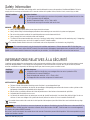
Special Conditions
of Use
Hazardous Locations
The equipment shall be installed in an enclosure that provides a degree of protection not less than
IP 54 in accordance with IEC 60079-0.
Ambient Temperature Range: -25°C ≤ Tamb ≤ 60°C
The enclosure must only be accessible with use of a tool.
WARNING:
Always de-energize power before accessing an electrical enclosure
Always follow safety and lockout/tagout procedures when working on or near electrical systems and equipment
Do not use this product outside of the specified performance and environmental limits
Always comply with local installation codes and standards
The data from the network module does not carry a functional safety rating. It should be used for monitoring only. If integrating
with a safety-rated system, use the SIL 3 outputs on the AVT isolation module.
The network module contains electronic circuit boards and can be disposed of at an electronics recycling facility.
INFORMATIONS RELATIVES À LA SÉCURITÉ
Le présent manuel contient des renseignements et des avertissements qui doivent être suivis pour assurer un fonctionnement en toute
sécurité du Network Module. Le non-respect des renseignements et des avertissements contenus dans le présent manuel pourrait
entraîner une défaillance du produit, des décharges électriques, des blessures graves ou même la mort.
Conditions
particulières
d’utilisation
Endroits dangereux
L’équipement doit être installé dans une enveloppe offrant au moins la protection IP54,
conformément à la norme IEC 60079-0.
Plage de température ambiante: -25°C ≤ Tamb ≤ 60°C
L’enveloppe doit être accessible uniquement à l’aide d’un outil.
AVERTISSEMENTS:
Toujours éteindre l’alimentation électrique avant d’accéder à une enveloppe électrique.
Toujours suivre les procédures de sécurité, de verrouillage et d’étiquetage pour exécuter des travaux sur des systèmes et des
équipements électriques ou à proximité de tels dispositifs.
Ne pas utiliser ce produit en dehors des limites de performance et des limites environnementales spécifiées.
Ce produit doit être installé et mis en serv.
Les données du module réseau ne portent pas une cote de sécurité fonctionnelle. Il ne devrait être utilisé qu’à des fins de sur-
veillance. Si vous vous intégrez à un système de sécurité, utilisez les sorties SIL 3 sur le module d’isolation AVT.
Le module réseau contient des cartes de circuits imprimés électroniques et peut être éliminé dans une installation de recyclage
électronique.
This instruction manual is only for the physical installation requirements. Refer to document B21176 (VS2-Net User
Guide) for instructions how to utilize VS2-NET functions, the web interface and logging / reporting data from connected 2.0 AVT system.
Updates to the network module firmware and user guide may be available. Visit www.panduit.com to access the latest versions.
Ce manuel d’instructions concerne uniquement les exigences d’installation physique. Référez-vous au document B21176
(guide d’utilisateur VS2-Net) pour des instructions comment utiliser des fonctions VS2-NET, l’interface web et se connecter/rapportant
des données du système 2.0 AVT connecté.
Des mises à jour du micrologiciel du module réseau et du manuel d’instructions peuvent être disponibles. Visitez www.panduit.com pour
accéder aux dernières versions.

10/16/2022 3 1006772, B21148_EN_rev1
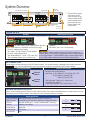
System Overview
+ + +
10/100 P0E
1A 1B 2A 2B 3A 3B
AVT
DC Intput AVT Connection Voltage Presence
Contacts Reset Button
(not shown)
Power Status
System Status Network
Connection
Termination Resistor Switch
POWER INPUTS
DC Input Network Connection (PoE)
The power supply must be surge protected, otherwise
external surge protection is required at the input to the supply.
IEC Class I regulated power supply
Min. Output: 12 VDC @ 100mA, 24 VDC @ 50mA
Connector / Wiring Requirements
Wire Range: AWG #24 - 14 SOL / STR (1 wire only)
Wire strip length: 9.0mm (min) / 10.0mm (max)
10/100 PoE
IEEE 802.3af Type 1 Class III PoE topology.
AVT CONNECTION
Provides power and communications to the AVT isolation module. The connection features a pluggable screw terminal connector.
Only install the network module in the same electrical enclosure as the VeriSafe 2.0 AVT isolation module.
Recommended Wiring Connector Specifications
Connector / Wiring Requirements;
Wire Range: (1 wire): AWG #24 - 12 [2.5mm2] SOL / STR
(2 wire): AWG #18 [1.0mm2] SOL
AWG #18 [1.5mm2] STR
Wire strip length: 7.0mm (min) / 8.0mm (max)
Screw Drive Size: M3x0.5
Screw Torque Required: 5.0 in-lb [0.57 N-m] +/- 10%
VOLTAGE PRESENCE OUTPUTS
Reflects status of Voltage presence LEDs on the AVT indicator module. These outputs are updated every 2 seconds based on the state
reported from the AVT isolation module. These outputs are not an indication of absence of voltage.
Output Specification
3 Solid-state Relay
Output Contacts Normally open, relays close when red AVT indicators are
illuminated (see AVT manual for red indicator voltage thresholds)
Wire Size AWG #26-16 AWG (0.13 - 1.3mm2) Solid/Stranded (1 wire only)
Isolation 5000 Vrms Input/Output
Voltage Rating 30V AC/DC
Current Rating 80 mA (max)
On-resistance 30 Ω
Output schematic
1A
1B
2A
2B
3A
3B
1
2
Network
Module
Isolation
Module
The termination resistor
switch below the AVT
connection ports on the
network module and AVT
isolation module shall be
positioned to the right
(factory default) when
facing the port
When using the network module with the 2.0 AVT isolation module, the
network module “AVT Connection” supplies power from the network module
to the isolation module. Therefore DO NOT apply an external power source
to the 2.0 AVT isolation module when used with the network module.

1006772, B21148_EN_rev1 4 10/16/2022
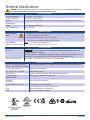
Technical Specifications
WARNING: Do not use this product outside of the specified performance and environmental limits. Failure to comply with
these specifications could result in product failure, personal injury, or death.
Environmental Ratings
Operating Temperature -25°C to 60°C (-13°F to 140°F)
Storage Temperature -45°C to 85°C (-49°F to 185°F)
Humidity 5 to 90% non-condensing; Rated 80% at 40°C (104°F), decreasing linearly to 50% at 60°C (140°F)
Pollution Degree 3
Altitude Up to 5000 meters (16400 feet)
Degree of Protection Open Type, IP20
Hazardous Locations
Special Conditions
of Use
The equipment shall be installed in an enclosure that provides a degree of protection not less than
IP 54 in accordance with IEC 60079-0.
Ambient Temperature Range: -25°C ≤ Tamb ≤ 60°C
The enclosure must only be accessible with use of a tool.
Network Module
(Hazardous Location Ratings) cULus: Class I, Division 2, Groups A, B, C, D
Class I Zone 2 AEx ec IIC T5 Gc; Ex ec IIC T5 Gc
Power Requirements
DC Input The power supply must be surge protected, otherwise external surge protection is
required at the input to the supply.
12-24 VDC (IEC Class I regulated power supply) Min. Output: 12 VDC @ 100 mA, 24 VDC @ 50 mA
Power Draw: 84 mA max @ 12 VDC; 42 mA max @ 24 VDC (Network Module + AVT)
Power over EtherNet (PoE) PoE (10/100), 15 mA, IEEE 802.at (-af) Type 1 Class III PoE topology
Standards and Certifications
IEC / UL / CSA C22.2 NO. 61010-1
IEC / UL / CSA C22.2 NO. 61010-2-030 Safety requirements for electrical equipment for measurement, control, and laboratory use
UL 508 & CSA-C22.2 No. 14 Industrial control equipment
FCC - CFR 47 Part 15 Subpart B Radio frequency devices
CAN ICES-001 Industrial, scientific and medical (ISM) radio frequency generators
EN 55011, CISPR 11,
AS/NZS CISPR 11
Radio frequency disturbance characteristics
IEC 61326-1
EN 61326-1 EMC and immunity requirements
IEC / EN 61000-3-2, -3-3, -6-2 Electromagnetic compatibility (EMC)
CE
UKCA Conformity Marking for European Economic Area
Conformity Marking for United Kingdom
RoHS Restriction of hazardous substances
Absence of Voltage
Accessory
Ind. Cont. Eq.
E489576

10/16/2022 5 1006772, B21148_EN_rev1
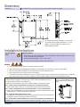
Dimensions
Dimensions 135 x 112 x 28 mm (5.3 x 4.4 x 1.1 inches), when network connetion is installed
Installation Instructions
Special Conditions
of Use
Hazardous Locations
The equipment shall be installed in an enclosure that provides a degree of protection not less than
IP 54 in accordance with IEC 60079-0.
Ambient Temperature Range: -25°C ≤ Tamb ≤ 60°C
The enclosure must only be accessible with use of a tool.
WARNING:
Always de-energize power before accessing an electrical enclosure
Always follow safety and lockout/tagout procedures when working on or near electrical systems and equipment
Do not use this product outside of the specified performance and environmental limits
Always comply with local installation codes and standards
The data from the network module does not carry a functional safety rating. It should be used for monitoring only. If integrating
with a safety-rated system, use the SIL 3 outputs on the AVT isolation module instead of the network module outputs.
STEP 1: INSTALL NETWORK MODULE INTO ENCLOSURE
Mount network module flat in enclosure (see *NOTE in dimensional diagram above), or
Snap the network module onto the DIN rail, or
Mount the network module to the 2.0 AVT isolation module. See image to the right.
STEP 2: CONNECT POWER TO NETWORK MODULE (DC POWER SUPPY, OR POWER OVER ETHERNET)
Connect power supply to DC Input, or connect PoE network cable to PoE connection
STEP 3: CONNECT THE DATA/POWER OUTPUT FROM NETWORK MODULE TO 2.0 AVT ISOLATION MODULE
Connect wires into pluggable screw terminal connectors on network module and the 2.0 AVT
isolation module. The connector ports are labeled “AVT”.
STEP 4: CONNECT NETWORK CONNECTION TO RJ-45 PORT
if using the DC Input connector for power, and not using PoE, connect RJ-45 network cable,
if using PoE, connect the PoE network cable to RJ-45 port
STEP 5: BEFORE POWER-UP, READ DOCUMENT B21110 (2.0 AVT INSTRUCTION MANUAL) AND DOCUMENT B21176
(NETWORK MODULE USER GUIDE) FOR USER AND WEB-INTERFACE INSTRUCTIONS. POWER UP THE SYSTEM.
IF DESIRED, ATTACH NETWORK MODULE
TO THE 2.0 AVT ISOLATION MODULE USING
SCREWS PROVIDED WITH THE NETWORK
MODULE
NOTE*:
For mounting the network module flat in an enclosure,
use the hole pattern locations identified by “A” in the
diagram. Use four #6 [M3.5] pan head screws or
other compatible fasteners.

Warranty
PANDUIT LIMITED PRODUCT WARRANTY
1. Limited Product Warranty. For purposes of this Limited Product Warranty, “Panduit products” mean all Panduit-branded products that Pan-
duit sells. Unless a different time period is set forth in the Panduit product manual, user guide or other product documentation, Panduit war-
rants that the Panduit product, and each part or component of the Panduit product, will comply with Panduit’s published specifications and
will be free from defects in material and workmanship for a period of 1 year from the date of invoice from Panduit or its authorized distributor,
not to exceed 18 months from the original date of shipment from Panduit’s facility.
2. Firmware. Unless otherwise provided in a separate license agreement, and subject to the limitations for third-party products set forth below,
Panduit warrants that any firmware contained in any Panduit products, when used with Panduit-specified hardware and when installed
properly, will perform in accordance with the Panduit published specifications for a period of 1 year from the date of invoice from Panduit or
its authorized distributor, not to exceed 18 months from the original date of shipment from Panduit’s facility. Any exceptions to this 1 year
warranty period will be identified in the Panduit product manual, user guide or other product documentation. Panduit does not warrant that
the operation of the firmware will be uninterrupted or error-free, or that the functions contained therein will meet or satisfy Buyer’s intended
use or requirements. Any warranties, if any, that Panduit provides for any standalone software that Panduit sells will be stated in the applicable
End User License Agreement.
3. Remedies. Panduit’s sole and exclusive obligation and Buyer’s exclusive remedy under this warranty is Panduit’s repair or replacement of
the defective Panduit product. Panduit shall have sole discretion as to which of these remedies Panduit will provide to Buyer. Buyer requested
on-site warranty service is not covered and will be at Buyer’s sole expense, unless authorized in writing by Panduit in advance of the com-
mencement of the on-site warranty service. Panduit has the right to either examine the Panduit products where they are located or, in its sole
discretion, issue shipping instructions for return of the product. Where applicable, Buyer must return the defective product, part or compo-
nent, transportation prepaid to Panduit’s customer service department accompanied by Panduit’s Return Material Authorization. If Panduit
confirms that there is a defect that is covered by this warranty, the repaired or replaced Panduit product will be warranted for the remainder
of the warranty period applicable to the originally shipped Panduit product, or for a period of 90 days from the date of shipment to Buyer,
whichever is longer.
4. No Warranty for Third-Party Products. Panduit makes no representations and disclaims all warranties of any kind, express or implied relative
to any third-party product or services, including any third-party software or firmware, which may be incorporated into a Panduit product and/
or resold or sublicensed by Panduit. To the extent any warranties extended to Panduit by the third-party manufacturer are transferable, Pan-
duit will transfer such warranties to Buyer and any enforcement of such third-party warranties shall be between the Buyer and the third-party.
Panduit does not warrant the compatibility of the Panduit products with the products of other manufacturers or Buyer’s application except to
the extent expressly represented in Panduit’s published specifications or written quotation.
5. Exclusions. Before using, Buyer shall determine the suitability of the Panduit product for his intended use and Buyer assumes all risk and
liability whatsoever in connection therewith. The warranties contained herein shall not apply to any Panduit products that have been subject-
ed to misuse, neglect, improper storage, handling, installation or accidental damage or modified or altered by persons other than Panduit
or persons authorized by Panduit. In addition, the firmware warranty does not cover any defects resulting from Buyer-supplied firmware or
unauthorized interfacing, operation outside of the environmental specifications for the products, or improper or inadequate site preparation
or maintenance by Buyer. Panduit products are not designed, intended or authorized to be used in medical applications or as components in
medical devices that are used to sustain or support human life. Should Buyer purchase or use a Panduit product for any such unintended or
unauthorized medical application, Buyer shall indemnify and hold Panduit harmless from any liability or damage whatsoever arising out of the
use of Panduit products in such medical applications.
6. LIMITATION ON LIABILITY. THE WARRANTIES PROVIDED HEREIN ARE BUYER’S SOLE AND EXCLUSIVE WARRANTIES. ALL IMPLIED WAR-
RANTIES, INCLUDING WITHOUT LIMITATION THE IMPLIED WARRANTIES OF MERCHANTABILITY OR FITNESS FOR ANY PARTICULAR USE
ARE DISCLAIMED. TO THE EXTENT PERMITTED BY LAW, IN NO EVENT SHALL PANDUIT BE LIABLE FOR ANY LOSS OR DAMAGES ARISING
FROM ANY PANDUIT PRODUCT WHETHER DIRECT, INDIRECT, CONSEQUENTIAL, INCIDENTAL OR SPECIAL, INCLUDING WITHOUT LIMITA-
TION ANY CLAIM FOR LOSS OF DATA, LOSS OF ACTUAL OR ANTICIPATED REVENUE, PROFITS OR SAVINGS.
7. General. This Limited Product Warranty applies to the Panduit products only and not to any combination or assembly of the Panduit prod-
ucts. Nothing in this Limited Product Warranty shall be construed to provide Buyer with a warranty for any system implementation using
Panduit products. The Panduit Certification Plus System Warranty is available for projects that are installed by Panduit Certified Installers,
meet various requirements and are registered with Panduit in accordance with the terms of the Panduit Certification Plus System Warranty.
-
 1
1
-
 2
2
-
 3
3
-
 4
4
-
 5
5
-
 6
6


dans d''autres langues
- English: Panduit VS2-NET User manual
Autres documents
-
Milwaukee 2878-22 Manuel utilisateur
-
-
-
-
-
Greenlee 52087649 REV0 Manuel utilisateur
-
-
-
-
Milwaukee 2779-22-2672-21 Manuel utilisateur