Jenn-Air JDS9860AAP Guide d'installation
- Catégorie
- Cuisinières
- Taper
- Guide d'installation

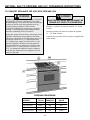
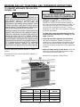
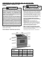
INSTALLATION MANUAL
Dual-Fuel 30-inch Wide
Jenn-Air Downdraft Range
INSTALLER: LEAVE THESE INSTRUCTIONS WITH THE APPLIANCE
8101P534-60
(01-03-00)
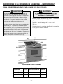
PLEASE KEEP THIS MANUAL FOR FUTURE REFERENCE
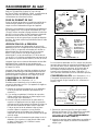
THE MANUAL IS INTENDED TO ASSIST IN THE INITI AL INSTALLATI ON AND ADJUSTMENTS OF THE RANGE.
Your range may not be equipped
with some of the features referred
to in this manual.
· ALL RANGES CAN TIP AND
CAUSE INJURIES TO PERSONS.
· INSTALL ANTI-TIP DEVICES
PACKED WITH RANGE.
· FOLLOW ALL INSTALLATION IN-
STRUCTIONS.
SPECIAL WARNING
Only qualified personnel should
install or service this range.
Read “Safety Instructions” in Use &
Care book before using range.
Improper installation, adjustment,
alteration, service, maintenance or
use of range can result in serious
injury or property damage.
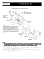
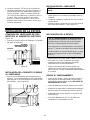
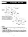
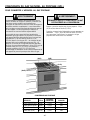
CLEARANCE DIMENSIONS
For complete information in regard to installation of
Jenn-Air range, see figures 1, 2, 3 and 4. For SAFETY
CONSIDERATIONS, do not install a range in any
combustible cabinetry which is not in accord with the
installation clearances shown in figure 1.
CAUTION: This range has been designed in
accordance with the requirements of various safety
agencies and complies with the maximum allowable
wood cabinet temperatures of 194°F. If this range
is installed with cabinets that have a lower working
temperature than 194°F, discoloration, delamination
or melting may occur.
ENGLISH '
''
' PP. 1-16
ESPAÑOL '
''
' pág. 17-32
FRANCAIS '
''
' p. 33-48

-2-
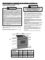
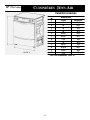
NOTES:
1. Provide for either a 3-wire or 4-wire 120/208, 120/240 volt outlet per applicable cord in shaded area shown. Refer
to installation instructions for proper positioning of outlet. This is also the recommended gas line location.
2. Dimension K (figure 3, page 3) is from the wall to the side edge of the oven door. It does not include the curvature
of the glass or the depth of the handle.
3. Dimension L (figure 3, page 3) is with the leveler legs adjusted all the way in. This may vary slightly upon leveling
leg adjustment.
4. Do not use grout, epoxy, etc., to install this unit. Installation must allow for removal of this appliance from the
installed location for purposes of servicing.
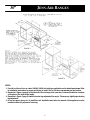
FIGURE 1
30²
²²
²
JENN-AIR RANGES
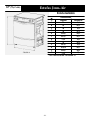
FIGURE 2

-3-
Slide-In Range
Dimensions
Inches
25
24
30
36
23 5/8
23 1/4
51/2
10
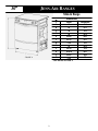
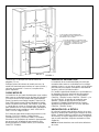
FIGURE 3
30²
²²
²
Centimeters
63.5
61.0
76.2
91.4
60.0
59.1
14.0
25.4
J
JJ
J
A
B
C
D
E
F
G
H
JENN-AIR RANGES
29 7/8
26 3/16
35 3/4
21/4
75.9
66.5
90.8
5.7
J
K
L
2*
3*
M
* SEE NOTES ON PAGE 2

-4-
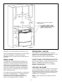
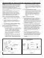
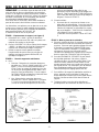
FIGURE 4
Dimension “A” is to be a minimum of 3-inches (7.5 cm).
Check the range model number plate to see if the range is
approved for installation in mobile homes and/or
recreational vehicles. If approved the following items are
applicable.
MOBILE HOMES
The installation of a range designed for mobile home
installation must conform with the Manufactured Home
Construction and Safety Standard, Title 24 CFR, Part
3280 [formerly the Federal Standard for Mobile Home
Construction and Safety, Title 24 HUD, (Part 280)] or,
when such standard is not applicable, the Standard for
Manufactured Home Installations, ANSI A225.1/NFPA
501A, or with local codes.
In Canada the range must be installed in accordance with
the current CSA Standard C22.1 - Canadian Electrical
Code Part 1 and Section Z240.4.1 - Installation
Requirements for Gas Burning Appliances in Mobile
Homes (CSA Standard CAN/CSA - Z240MH).
RECREATIONAL VEHICLES
The installation of a range designed for recreational
vehicles must conform with state or other codes or, in the
absence of such codes, with the Standard for
Recreational Vehicles, ANSI A119.2-latest edition.
In Canada the range must be installed in accordance with
CAN/CSA - Z240.6.2 - Electrical Requirements for R.V.’s
(CSA Standard CAN/CSA - Z240 RV Series) and Section
Z240.4.2 - Installation Requirements for Propane
Appliances and Equipment in R.V.’s (CSA Standard
CAN/CSA - Z240 RV Series).
LOCATING THE RANGE
Do not set range over holes in the floor or other locations
where it may be subject to strong drafts. Any opening in
the wall behind the range and in the floor under the range
should be sealed. Make sure the flow of combustion or
ventilation air is not obstructed.
NOTE: A range should NOT be installed over kitchen
carpeting.

-5-
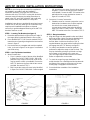
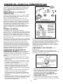
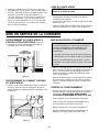
ANTI-TIP DEVICE INSTALLATION INSTRUCTIONS
NOTE: A risk of range tip over exists if the appliance is
not installed in accordance with the installation
instructions provided. The proper use of this device
minimizes the risk of TIP-OVER. In using this device the
consumer must still observe the safety precautions as
stated in the USE and CARE MANUAL and avoid using
the oven door and/or lower drawer as a step stool.
Installation instructions are provided for wood and cement
in either floor or wall. Any other type of construction may
require special installation techniques as deemed
necessary to provide adequate fastening of the ANTI-TIP
bracket to the floor or wall.
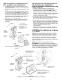
STEP 1 - Locating The Bracket (see figure 5)
A. Determine where either the right or left rear “edge” of
the range will be located and mark the floor or wall.
B. Place the BRACKET 15/16² from the marked “EDGE”
toward center of opening and against the back wall as
shown in figure 5.
C. Use the bracket as a template and mark the required
holes, as shown in figure 5 for the type of construction
you will be using.
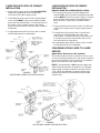
STEP 2 - Anti-Tip Bracket Installation
A. Wood Construction:
1. Floor: Locate the center of the two holes identified
in figure 5 as “HOLES FOR FLOOR”. Drill a 1/8²
pilot hole in the center of each hole (a nail or awl
may be used if a drill is not available). Secure the
ANTI-TIP bracket to the floor with the two screws
provided. Proceed to STEP 3.
2. Wall: Locate the center of the two holes identified
in figure 5 as “HOLES FOR WALL. Drill an angled
1/8² pilot hole in the center of each hole as shown
in figure 6. (A nail or awl may be used if a drill is
not available). Secure the ANTI-TIP bracket to the
wall with the two screws provided as shown in
figure 6. Proceed to STEP 3.
B. Cement or Concrete Construction:
1. Suitable screws for concrete construction can be
obtained at a hardware store. Drill the required
size hole for the screws obtained into the
concrete at the center of the holes identified in
figure 5 as “HOLES FOR FLOOR”. Secure the
ANTI-TIP bracket to the floor. Proceed to STEP 3.
STEP 3 - Range Installation
A. Align the range to its designated location and slide it
back into position. Make sure that the leveling foot is
fully inserted into and secured by the ANTI-TIP
bracket. Note: A minimum clearance of 1/4² is
required between the range and the leveling foot that
will engage the ANTI-TIP bracket, see figure 6.
B. For safety considerations as well as optimum
performance adjust the range so that it is level. This
may be checked by placing a spirit level or a large
pan of water on the cooktop or the oven rack.
Jenn-Air ranges require total removal from cabinet
before an adjustment can be made.
C. To check the range for proper installation of the
anti-tip bracket: Use a flashlight and look underneath
the bottom of the range to see that one of the rear
leveling legs is engaged in the bracket slot.
D. Proceed with the remainder of the installation
instructions.
FIGURE 5 FIGURE 6

-6-
FIGURE 7
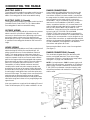
CONNECTING THE RANGE
ELECTRIC SUPPLY
The range must be installed in accordance with Local and
National Electric Code (NEC) ANSI/NFPA No. 70-latest
edition. See rating plate for total connected KW rating.
ELECTRIC SUPPLY (Canada)
The range must be installed in accordance with Local and
Canadian Electric Code CSA STD.C22.1 latest edition.
See rating plate for total connected KW rating.
OUTSIDE WIRING
Your local utility company will tell you whether the present
electric service to your home is adequate. It may be
necessary to increase the size of the wiring to the house
and service switch to take care of the electrical load
demanded by the range. The kilowatt rating for the range
is specified on the rating plate located on the front of the
range.
HOUSE WIRING
Most local Building Regulations and Codes require that all
electrical wiring be done by licensed electricians. All
wiring should conform to Local and National Electrical
Codes. This range requires a single phase three wire
120/240 or a 120/208 volt, 60 Hz, AC circuit. Wiring codes
require a separate circuit be run from the main entrance
panel to the range and that it be equipped with separate
disconnect switch and fuses, either in the main entrance
panel or in a separate switch and fuse box. In some
communities, a solid or flexible continuous armored
conduit must be used from main entrance panel to the
terminal box on the rear of the range. Others will permit
the termination of the range circuit at a polarized three or
four wire plug-in outlet placed at a convenient point near
the back of the range. The range is then connected to this
outlet through an approved range connector (pigtail)
fastened securely to the terminal block with proper strain
relief at the range and a three or four pronged plug at the
opposite end.
User may experience occasional circuit tripping if Ground
Fault Circuit Interrupter (GFCI) outlet or breaker is in use.
RANGE CONNECTIONS
Some models are shipped direct from the factory with
service cords (pigtails) attached. There are no range
connections necessary on these models. Just plug into
the range outlet. On models not provided with a service
cord, connection to the power supply is necessary.
REMEMBER - only a 4-conductor cord is to be used on
new branch-circuit installations (1996 NEC), mobile
homes, recreational vehicles, or in an area where local
codes prohibit grounding through the neutral conductor.
Hence, 4-wire service MUST be provided for such
installations. 3-wire service may be used when permitted
by local code. USE COPPER OR ALUMINUM
CONDUCTORS. Main terminal block is recognized for
Copper or Aluminum conductors. If a flexible power cord
is required, it is recommended a cord no longer than 4 ft.
be used. Make connections as explained below and with
reference to the appropriate illustration (see figures 8 and
9). After installation, insure tightness of all electrical
connections and replace all covers.
Remove terminal block access cover from range back.
(See figure 7).
RANGE CONNECTIONS (Canada)
This model was shipped direct from the factory with
service cord (pigtail) attached. There are no range
connections necessary. Just plug into the range outlet.
See figure 2 on page 3 for outlet location.
NOTE: Cord replacement - ONLY a power supply cord
rated at 240 volts minimum, 40 amperes or 50 amperes
power supply cord that is marked for use with nominal
13/8² (34.93 mm) diameter connection opening, with
closed loop terminals and marked for use with ranges
shall be used.

-7-
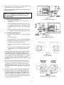
3-WIRE SERVICE CORD OR CONDUIT
INSTALLATION
1. Insure that the copper ground strap IS CONNECTED
between the middle post of the main terminal
connection block and the range chassis.
2. The middle wire of the service cord or ground lead of
3-wire conduit MUST connect to the neutral (middle)
post of the main terminal block. The other two wires of
the service cord or conduit connect to the outside
posts of the main terminal connection block. Polarity is
unimportant.
3. A appropriate strain relief for service cord or conduit
must be attached to the conduit plate.
FIGURE 8
ACCEPTABLE 3-WIRE PLUG INSTALLATION
4-WIRE SERVICE CORD OR CONDUIT
INSTALLATION
(MOBILE HOMES OR AS REQUIRED BY CODES)
1. The copper ground strap connected between the
neutral (middle) post of the main terminal block and the
chassis MUST be cut off as shown in figure 9. Save the
green ground screw to attach the ground from the 4
wire cord. Only a 4 wire cord or conduit should be
used.
2. The ground wire from the service cord or conduit must
connect to the range chassis using the green ground
screw.
3. The white wire of the service cord or conduit must
connect to the neutral (middle) post of the main
terminal block. The other two wires of the service cord
or conduit connect to the red and black posts of the
main terminal block, respectively.
4. An appropriate strain relief for service cord or conduit
must be attached to the conduit plate.
CONVERSION FROM 3-WIRE TO 4-WIRE
SERVICE
(Model With 3-Wire Service Cord Attached)
Disconnect range from power. Remove the access cover
on back of range and remove the 3-wire service cord from
the main terminal block. Follow instructions as outlined in
figure 9 to connect the 4-wire service cord.
NOTE: Cord replacement - ONLY a power supply cord
rated at 240 volts minimum, 40 amperes or 50 amperes
power supply cord that is marked for use with nominal
13/8² (34.93 mm) diameter connection opening, with
closed loop terminals and marked for use with ranges
shall be used.
FIGURE 9
ACCEPTABLE 4-WIRE PLUG INSTALLATION

-8-
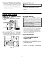
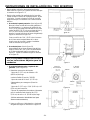
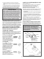
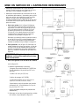
S Determine where you will be locating the electrical
outlet. It must be in the floor or on the wall within the
area shown in figure 2 or 3.
S Determine how you will be venting your downdraft
blower. You may vent through the rear wall, the floor,
or the sides. When locating the downdraft vent
opening make sure it will not interfere with your
electrical outlet.
a. Through the rear wall. (See figure 10) Mark the
centerline of the cabinet opening on the rear wall.
The61/4² vent opening must be located on a
centerline 8 3/8² above the floor and within 3 1/4²
to the right (when facing the cabinet opening) of
the centerline of the cabinet opening as shown in
figure 10.
Cuta61/4² diameter hole on the marked
centerline making sure to miss any wall studs.
Install the blower as shown in figure 12.
b. Through the floor. (See figure 11) Making sure to
miss any floor joists cut a 6 1/4² diameter hole in
the shaded area as shown in figure 11. Install the
blower as shown in figure 12.
NOTE: If the floor is a concrete slab, see
the enclosed ducting instructions.
c. Through the Left or Right side cabinet.
(See figure 13).
1. Additional materials required:
1pc5² diameter x 19² long (12.7 cm x 48.26
cm).
Flex duct (P/N 702935).
1pc6² (15.25 cm) 90_ elbow.
2 Hose Clamps (P/N 702331).
1pc5² to31/4² x10² (12.7cmto8.26cmx
25.4 cm) Transition.
2 pcs Wood spacers (right side vent only)
11/2² thickx9² long (3.81 cm x 22.68 cm).
(See your local dealer for these accessories).
2. Cut hole in either the left or right side of the
cabinet wall as shown in figure 13.
Figure 10
DOWNDRAFT INSTALLATION INSTRUCTIONS
Figure 11
Figure 12
Figure 13

-9-
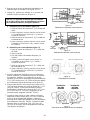
NOTE: The mounting brackets shown in figure
16 are as assembled at the factory for floor or
rear wall venting.
a. Right side venting (figure 17).
1. Remove nuts from studs 1, 2 and 3 on the
motor side.
2. Remove bracket and reattach with studs 1 and
2 inserted in holes A and C and replace 3 nuts.
3. Remove nuts from studs 5, 6 and 7 on air inlet
side.
4. Remove bracket and reattach with studs 5 and
6 inserted in holes D and B and replace 3 nuts.
b. Left side venting (figure 17).
1. Remove nuts from studs 1, 2, 3 and 4 on motor
side.
2. Remove bracket.
3. Rotate motor and cover assembly 180 degrees.
4. Reattach bracket with studs 4 and 1 inserted in
holes A and C and replace all 4 nuts.
5. Remove nuts from studs 5, 6, 7 and 8 on inlet
side.
6. Remove bracket and reattach with studs 8 and
5 inserted in holes D and B and replace all 4
nuts.
5. Attach the blower housing to the floor with the outlet
towards the direction of the venting and the inlet
towards the front of the cabinets. In addition, for left
side venting, a spacer of approximately 1-1/2² thick x
9² long (3.81 cm x 22.86 cm) is required under the
mounting bracket flanges of the blower assembly (see
figure 17).
6. Remove the inside wire and outside string from the
first 1-1/2² (3.81 cm) of one end of the 5² (12.7 cm)
flex duct (P/N 702935). Stretch this end of the flex
duct over the end of the 5² x3-1/4² x10² (12.7 cm x
25.4 cm) transition and secure with hose clamp (P/N
702331).
7. When the range is placed in position, feed the open
end of the 5² (12.7 cm) flex duct through the hole in
the cabinet side wall and attach to the outlet of the
blower housing with hose clamp (P/N 702331). The
transition should then be attached to the 3-1/4² x10²
(12.7 cm x 25.4 cm) ducting in the cabinet toe space
through the cabinet floor cutout.
Figure 15
Right Cabinet (Top View)
Figure 16
Blower Assembly
Figure 17
View from Air Inlet Side of Blower
3. Make cutout in the cabinet floor of either the right or left
side cabinet as shown in figures 14 or 15.
4. Relocatethemountingbracketsontheblowerhousingas
shown in figure 17.
Figure 14
Left Cabinet (Top View)

-10-
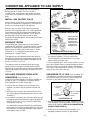
RANGE INSTALLATION
CONNECTING THE DOWNDRAFT BLOWER
TO ELECTRICAL (Figure 18)
S Connect the blower power cord to the blower motor
housing.
INSTALLING THE FLEX DUCT TO BLOWER
S Use one of the duct clamps provided. Using a screw
driver, tighten duct clamp to secure the flex duct to the
inlet of the blower. (See figure 19).
INSTALLING THE BLOWER
NOTE: Install the blower prior to installing the
range.
S Refer to your duct plan. It may be easier to attach part
of the ducting to the blower before it is installed.
S Position the blower and attach to the floor with at least
2 screws.
S Apply duct tape to blower exhaust duct joint. (See
figure 12).
8. Install the 6² (15.24 cm) elbow of the blower housing
and secure with duct tape. The open end of the elbow
should be pointed to the left. Attach the 6² (15.24 cm)
flex duct (provided with the range) to the elbow and to
the range. Note: For right side venting, the 6² (15.24
cm) diameter flex duct may be cut in half and used in
order to make assembly easier.
Figure 18
Figure 19
INSTALLING THE RANGE
In The Commo n wealth Of Massachusetts
This product must be installed by a licensed plumber or
gas fitter when installed within the Commonwealth of
Massachusetts.
A “T” handle type manual gas valve must be installed in
the gas supply line to this appliance.
A flexible gas connector, when used, must not exceed a
length of three (3) feet / 36 inches.
S Align the range to its designated location and slide
back into position. Make sure that the rear leveling leg
is fully inserted and secured by the anti-tip bracket.
S Attach the other end of the flex duct to the plenum of
the range using the second duct clamp. Tighten duct
clamp to secure it to the plenum.
CHECK FOR OPERATION
S Install the air filter. As you face the range, the top of
the filter should rest against the left side of the vent
opening. DO NOT OPERATE THE SYSTEM
WITHOUT THE FILTER.
S Install the air grille over the vent opening.
S Be sure to remove all packing materials the oven from
unit prior to applying power.
S Switch electrical circuit breaker to the ON position.
S Consult USE and CARE MANUAL for proper operation.

-11-
A QUALIFIED SERVICEMAN OR GAS APPLIANCE
INSTALLER MUST MAKE THE G AS SUPPLY
CONNECTION. Leak testing of the appliance shall be
conducted by the installer according to the instructions
given.
INSTALL GAS SHUTOFF VALVE
Install a manual shutoff valve in an accessible location in
the gas line external to this appliance for the purpose of
turning on or shutting off gas to the appliance.
Make the gas connection to the inlet of the pressure
regulator on this appliance with a 1/2² male pipe thread.
Use an approved pipe joint compound resistant to the
action of LP gas at pipe connections. Test all joints for
gas leaks with a soap and water solution or other
accepted leak detection means. Never test for gas leaks
with an open flame.
PRESSURE TESTING
The maximum gas supply pressure for the regulator
supplied on this appliance is 14² Water Column. The test
pressure for checking this regulator must be at least 6²
Water Column for natural gas, and at least 11² Water
Column for LP. It is shipped from the factory set for
natural gas at 5² Water Column.
This appliance and its individual shutoff valve must be
disconnected from the gas supply piping system during
any pressure testing of that system at test pressures in
excess of 1/2 PSIG (3.5 k Pa).
This appliance must be isolated from the gas supply
piping system by closing its individual manual shutoff
valve during any pressure testing of the gas supply piping
system at test pressures equal to or less than 1/2 PSIG
(3.5 k Pa).
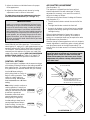
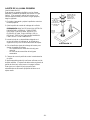
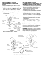
APPLIANCE PRESSURE REGULATOR
CONVERSION
(See illustration “A”)
Follow the instructions below to convert the regulator for
use with LP gas. (This appliance is shipped from the
factory adjusted for use with natural gas.)
1. Unscrew the hex shaped cap from the neck of the
regulator. (A wrench may be required to loosen the
cap.)
2. Within the cap is a plastic pin. Remove this pin from
the cap by applying sideward pressure to the pin. (See
illustration.)
3. Invert the pin and snap it back into place within the cap
by applying even finger pressure at opposing edges of
the pin’s circular disc. The pin must be seated firmly
and squarely in the cap.
Pin replacement may be most easily accomplished by
placing the cap on a flat horizontal surface, as shown in
the illustration, and applying downward finger pressure
at the edges of the pin’s disc.
CONNECTING APPLIANCE TO GAS SUPPLY
MAXITROL REGULATOR
ILLUSTRATION “A”
HARPER-WYMAN REGULATOR
ALTERNATE ILLUSTRATION “A”
The reversible cap is
labeled either “LP” or
“NAT” and is easily
recognized by the
raised center coin slot
(for Natural) or the
center well (for LP).
4. Screw the cap securely back into place in the neck of
the pressure regulator. (The cap need not be
wrench-tightened upon replacement. Firm finger
tightening will secure the cap.)
To convert regulator to LP insert a coin into the slot in the
cap of the regulator and turn counterclockwise to loosen.
Reverse (invert) cap, push down and turn clockwise to
lock in place. When finished, the marking “LP” should be
visible in the center well of the cap.
CONVERSION TO LP GAS (See illustration “B”)
This appliance is shipped from the factory equipped for
use with natural gas. To convert it from natural gas for
use with LP gas, perform steps 1 through 4.
1/2² OPEN END
WRENCH
TURN
COUNTERCLOCKWISE
TO REMOVE
ORIFICE HOOD
TURN CLOCKWISE
TO TIGHTEN
ILLUSTRATION “B”
1. Remove natural gas orifice hoods. Remove LP orifice,
(if so equipped) in tube assemblies. Install color coded
orifice hoods supplied. (SEE LP GAS CONVERSION
INSTRUCTIONS PAGE 15.)
2. Invert cap in convertible pressure regulator (if so
equipped) located at entrance to gas manifold.

-12-
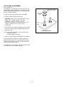
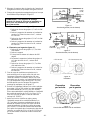
AIR SHUTTER ADJUSTMENT
(See illustration “C”)
This appliance is shipped from the factory with air
shutters adjusted for use with natural gas. If further
adjustment is necessary, or to reset for use with LP,
adjust air shutters as follows:
Grill Burner and Surface Burner Cartridge Air Shutters
(see illustration “C”).
S The left hand air shutter controls the rear half of the
burner.
S The right hand shutter controls the front half.
S Access to air shutters on the surface burner cartridge
may be found through openings on the bottom of the
cartridge housing.
Slide air shutter backward or forward to increase or
decrease the size of the air opening. Air shutters fit
snugly, so a screwdriver blade may be required to make
this adjustment (see illustration.)
Observe change in flame appearance as the air shutter is
moved. Adjustment is satisfactory when a clearly defined,
even blue flame results at the high flame setting. The
snug fit of the air shutter assures it will remain positioned
correctly.
On any burner, closing the air shutter too far will
cause the flame to become soft and yellow tipped.
Opening the air shutter too wide will cause the
flame to blow away from the burner ports. Proper
adjustment will produce a sharp, clearly defined,
even blue flame.
3. Adjust air shutters on individual burners for proper
flame appearance.
4. Adjust low flame setting at each burner by turning
adjustment screw in center of valve stem.
To make these conversion adjustments follow the
instructions and illustrations (“A” through “D”).
IMPORTANT
Apply a non-corrosive leak detection fluid to all joints
and fittings in the gas connection between the supply
line shut-off valve and the range. Include gas fittings
and joints in the range if connections were disturbed
during installation. Check for leaks! bubbles appearing
around fittings and connections will indicate a leak. If
a leak appears, turn off supply line gas shut-off valve,
tighten connections, turn on the supply line gas shut
off valve, and retest for leaks. Never test for gas leaks
with an open flame.
This appliance is shipped from the factory with orifice
hoods drilled for use with natural gas. To convert from
natural gas to LP, apply a 1/2² open-ended wrench to hex
section of orifice hood. TURN COUNTERCLOCKWISE
TO REMOVE. Save the Natural Gas orifice hoods just
removed from this appliance for future use. Install color
coded orifice hoods supplied. (SEE GAS CONVERSION
INSTRUCTIONS PAGE 14.) TURN CLOCKWISE TO
INSTALL. Hold dimension specified in illustration “B”.
CONTROL SETTINGS
The size and type of cookware and the amount and type
of food being cooked will influence the setting needed for
best cooking results. The setting indicated should serve
as a guide while you become familiar with your cooktop.
Use the Hi flame setting to
quickly bring foods to a boil or to
begin a cooking operation. Then
reduce to a lower setting to
continue cooking. Never leave
food unattended over a Hi flame
setting.
Med setting is used to continue a
cooking operation. Food will not
cook any faster when a Hi flame
setting is used than that needed
to maintain a gentle boil.
Remember, water boils at the
same temperature whether
boiling gently or vigorously.
Use Lo setting to keep food at
serving temperatures without
further cooking. You may find
that some cooking may take
place if the cookware is covered.
ILLUSTRATION “C”
AIR OPENING
AIR SHUTTER
INSERT SCREWDRIVER BLADE
IN SLOT AND TWIST WITH
SLIGHT PRESSURE TO ALLOW
AIR SHUTTER TO SLIDE EASILY.
GRILL BURNER AIR SHUTTER & SURFACE BURNER
(IF SO EQUIPPED)

-13-
LOW FLAME ADJUSTMENT
(See illustration “D”)
This appliance is shipped from the factory with low and
medium flame settings adjusted for use with natural gas.
If further adjustment is necessary, or to readjust for use
with LP, proceed as follows:
1. Light burner and set control knob for low flame.
2. Remove control knob from valve stem.
CAUTION: NEVER USE A METAL BLADE TO PRY
KNOB OFF. IF KNOB CANNOT BE EASILY
REMOVED, TUCK FOLDS OF A CLOTH
DISHTOWEL UNDER THE KNOB AND PULL THE
TOW EL UPWARD WITH STEADY, EVEN
PRESSURE.
3. Insert a slender, thin-blade screwdriver into the recess
at center of valve stem and engage blade with slot in
adjusting screw.
4. Turn center stem adjusting screw to set flame size.
...clockwisetoreduce.
...counterclockwise to increase.
5. Replace control knob when adjustment is completed.
Proper adjustment will produce a stable, steady blue
flame of minimum size. The final adjustment should be
checked by turning knob from high to low several times
without extinguishing the flame.
This adjustment, at low setting, will automatically provide
the proper flame size at medium setting.
ILLUSTRATION “D”
COUNTERCLOCKWISE
TO INCREASE FLAME
SIZE
CLOCKWISE
TO REDUCE
SIZE
VALV
E
STEM

-14-
NATURAL GAS TO PROPANE GAS (LP) CONVERSION INSTRUCTIONS
WARNING
TO CONVERT APPLIANCE FOR USE WITH PROPANE GAS
Manifold - Propane Gas pressure required - 10² Water
Column.
Incoming Propane Gas pressure required to regulator -
11² -14² Water Column.
Propane Gas conversion Orifice Hoods are supplied with
these models.
PROPANE CONVERSION
Propane conversion is to be performed by a JENN-AIR
AUTHORIZED SERVICE CONTRACTOR (or other
qualified agency) in accordance with the manufacturer’s
instructions and all codes and requirements of the
authority having jurisdiction. Failure to follow
instructions could result in serious injury or property
damage. The qualified agency performing this work
assumes responsibility for this conversion.
Natural gas supply line must have a natural gas service
regulator. Inlet pressure to this appliance should be
reduced to a maximum of 14 inches water column (0.5
pounds per square inch (P.S.I.) liquified petroleum
(L.P.)/propane gas supply line must have a L.P. gas
pressure regulator. Inlet pressure to this appliance
should be reduced to a maximum of 14 inches water
column (0.5 P.S.I.). Inlet pressures in excess of 0.5
P.S.I. can damage the appliance pressure regulator
and other gas components in this appliance and can
result in a gas leak.
WARNING
ELECTRICAL POWER AND GAS MUST BE
TURNED OFF PRIOR TO CONVERSION.
INCHES
BURNER BTU/hr DIAMETER COLOR
Left Rear (LR) 8,000 .033 Zinc
Left Front (LF) 8,000 .033 Zinc
Right Rear (RR) 8,500 .035 Green
Right Front (RF) 8,500 .035 Green

-15-
PROPANE GAS (LP) TO NATURAL GAS CONVERSION INSTRUCTIONS
WARNING
TO CONVERT APPLIANCE FOR USE WITH
NATURAL GAS
1. Replace all orifice hoods ...Performstep1
through 4 on pages 12 & 13. Locate the (4) four
Natural Gas hoods (with small numbers stamped on
their sides) saved from original Natural Gas model. The
two hoods with .0520 (#55 orifice) stamped on them
are for the left front and left rear burners. The two
hoods with the .0595 (#53 orifice) stamped on them are
for the two right burners.
To make these conversion adjustments follow the
instructions and illustrations (“A” through “D”) on
pages 13 and 14.
2. Invert cap in pressure regulator (see illustration
“A”). With the appliance installed, the regulator is
located on the center underside of the appliance at the
inlet to the gas manifold. Identify the type of regulator
on the unit and follow the instructions in the appropriate
illustration.
3. Adjust low flame setting for each burner. Follow the
instructions for burner low flame adjustment on page
14 to increase the simmer flame size.
Natural Gas input required - 36,000 BTU/hr.
Natural Gas conversion is to be performed by a
JENN-AIRAUTHORIZEDSERVICE CONTRACTOR(or
other qualified agency) in accordance with the
manufacturer’s instructions and all codes and
requirements of the authority having jurisdiction. Failure
to follow instructions could result in serious injury or
property damage. The qualified agency performing this
work assumes responsibility for this conversion.
Natural gas supply line must have a natural gas service
regulator. Inlet pressure to this appliance should be
reduced to a maximum of 14 inches water column (0.5
pounds per square inch (P.S.I.) liquified petroleum
(L.P.)/propane gas supply line must have a L.P. gas
pressureregulator. Inletpressuretothis applianceshould
be reduced toamaximum of 14 incheswater column (0.5
P.S.I.).Inletpressuresinexcessof0.5P.S.I.candamage
the appliance pressure regulator and other gas
componentsinthisapplianceandcanresult inagas leak.
WARNING
ELECTRICAL POWER AND GAS MUST BE
TURNED OFF PRIOR TO CONVERSION.
Manifold - Natural Gas pressure required - 5² Water
Column.
Incoming Natural Gas pressure required to regulator - 6² -
7² Water Column.
INCHES
BURNER BTU/hr DIAMETER COLOR
Left Rear (LR) 8,000 .0520 Brass
Left Front (LF) 8,000 .0520 Brass
Right Rear (RR) 10,000 .0595 Brass
Right Front (RF) 10,000 .0595 Brass

-16-
BURNER CAPS AND SEALED
GAS
BURNERS
S Allow burner to cool. Remove burner cap and wash in
soapy water with a plastic scouring pad or in the
dishwasher. For stubborn soils, clean with a soap-filled,
nonabrasive pad or Cooktop Cleaning Creme (Part
#20000001).
S For burned on soil, place burner cap on newspaper and
spray with commercial oven cleaner. Follow
manufacturer’s directions.
S Clean gas ports with a straight pin especially the port
below the ignitor. Do not enlarge or distort holes.
S Be careful not to get water into burner ports.
S When cleaning, use care to prevent damage to the
ignitor. If the ignitor is soiled, wet or damaged the
surface burner will not light.
HOW TO REMOVE RANGE FOR
CLEANING AND
SERVICING
Follow these procedures to remove appliance for
cleaning or servicing:
1. Shut off gas supply to appliance.
2. Disconnect electrical supply to appliance, if equipped.
3. Disconnect gas supply tubing to appliance.
4. Slide range forward to disengage range from the
anti-tip bracket. (See page 5).
5. Reverse procedure to reinstall. If gas line has been
disconnected, check for gas leaks after reconnection.
NOTE: A qualified servicer should disconnect and
reconnect the gas supply.
6. To prevent range from accidentally tipping, range must
be secured to the floor by sliding rear leveling leg into
the anti-tip bracket.

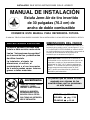
MANUAL DE INSTALACIÓN
Estufa Jenn-Air de tiro invertido
de 30 pulgadas (76.2 cm) de
ancho de doble combustible
INSTALADOR: DEJE ESTAS INSTRUCCIONES CON EL APARATO
CONSERVE ESTE MANUAL PARA REFERENCIA FUTURA
EL MANUAL TIENE LA FINALIDAD DE AYUDARLE EN LA INSTALACIÓN Y LOS AJUSTES INICIALES DE LA ESTUFA.
Es posible que su estufa no esté
equipada con algunas de las
características que se mencionan
en este manual.
· TODAS LAS ESTUFAS PUEDEN
LADEARSE Y CAUSAR
LESIONES A LAS PERSONAS.
· INSTALE LOS SOPORTES
ESTABILIZADORES QUE SE
INCLUYEN CON LA ESTUFA.
· SIGA TODAS LAS INSTRUCCIO--
NES DE INSTALACIÓN.
ADVERTENCIA ESPECIAL
Solamente personal calificado debe
instalar o darle servicio a esta estufa.
Lea las “Instrucciones de seguridad”
en el manual de Uso y cuidado antes
de utilizar la estufa.
La instalación, el ajuste, las
alteraciones, el servicio, el
mantenimiento o el uso incorrectos
de la estufa pueden causar lesiones
graves o daños materiales.
DIMENSIONES DEL HUECO
Para obtener la información completa relacionada con la
instalación de la estufa Jenn-Air, vea las figuras 1, 2, 3 y
4. Por RAZONES DE SEGURIDAD no instale la estufa
en ningún gabinete que sea combustible y que no esté de
acuerdo con las dimensiones de los espacios de
instalación que se muestran en la figura 1.
PRECAUCIÓN: Esta estufa se ha diseñado en
conformidad con los requisitos de varias agencias de
seguridad y cumple con las temperaturas máximas
permisibles de 194°F(90°C) para los gabinetes de
madera. Si se instala esta estufa en gabinetes que
tengan temperatura de trabajo menor de 194°F
(90°C), podría ocurrir decoloración, pérdida del
laminado o podría derretirse.
ADVERTENCIA
ENGLISH '
''
' PP. 1-16
ESPAÑOL '
''
' pág. 17-32
FRANCAIS '
''
' p. 33-48

-18-
FIGURA 1
FIGURA 2
* CUANDO ESTÉ REEMPLAZANDO UNA UNIDAD EXISTENTE, LA MÁXIMA
PROFUNDIDAD DEL CORTE DE 23 1/2² (59.7 CM) SERÁ ACEPTABLE.
*
PROFUNDI
DAD DEL
CORTE
“F”
ANTESDETRATARDE
INSTALARLA, AJUSTE
LAS PATAS
NIVELADORAS PARA
QUESEAJUSTENA
ESTA DIMENSIÓN.
ALTURA A LA PARTE
SUPERIOR DEL MOSTRADOR
“D”
ABERTURA DEL
GABINETE “C”
VEA LA
NOTA
NO. 1
PRECAUCIÓN:
ALGUNOS GABINETES DE ESTILO EUROPEO EN COLOR BLANCO
ESTÁN EQUIPADOS CON FRENTES DE VINILO DELICADO EN
COLOR BLANCO EN EL CAJÓN Y EN LA PUERTA. ESTE VINILO
PODRÍA NO ESTAR DISEÑADO PARA SOPORTAR EL CALOR
PRODUCIDO POR LA OPERACIÓN SEGURA NORMAL DE UNA
ESTUFA CON LIMPIEZA AUTOMÁTICA. PODRÍA OCURRIR
DECOLORACIÓN O DELAMINACIÓN. SE RECOMIENDA AUMENTAR
LA ABERTURA DEL GABINETE DE 30² (76.2CM)A311/4² (79.4 CM)
CUANDO MENOS Y USAR UN JUEGO DE CORAZA PROTECTORA
CONTRA CALOR (CABKIT V). LA CUAL PUEDE PEDIRSE POR
SEPARADO. EL CORTE DEL MOSTRADOR DEBE PERMANECER DE
30² (76.2 CM)
ALTURA A LA PARTE
SUPERIOR DEL
MOSTRADOR “D”
VEA LA
NOTA
NO. 1
ABERTURA
DEL GABINETE
“C”
PROFUNDIDA
DDEL
GABINETE “B”
PROFUN--
DIDAD
NORMAL DE
LA SUPER--
FICIE DEL
MOSTRADOR
“A”
PROFUNDIDAD NORMAL DE
LA SUPERFICIE DEL
MOSTRADOR “A”
PROFUNDIDAD DEL
GABINETE “B”
ÁREA
HORIZONTA
L MÍNIMA “E”
NOTA:
EN LAS SUPERFICIES DE LOS
MOSTRADORES CON BORDE
DELANTERO FORMADO, REBAJE
LA SECCIÓN REALZADA PARA
LIBRAR LA PARTE SUPERIOR.
NOTAS:
1. Provea un tomacorriente de 120/208, 120/240 voltios de 3 ó 4 cables por cordón eléctrico correspondiente en el
área sombreada que se muestra. Consulte las instrucciones de instalación para obtener la colocación correcta
del tomacorriente. Ésta es también la localización recomendada de la tubería de s uministro de gas.
2. La dimensión K (figura 3, página 19) es de la pared al borde lateral de la puerta del horno. No incluye la curvatura
del vidrio ni la profundidad del asa.
3. La dimensión L (figura 3, página 19) es con las patas niveladoras ajustadas completamente. Esto podría variar
ligeramente dependiendo del ajuste de las patas niveladoras.
4. No use lechada, epoxia, etc., para instalar esta unidad. La instalación debe permitir que se pueda quitar este
aparato de su lugar para fines de servicio.
30²
²²
² (76.2 cm)
Estufas Jenn--Air

-19-
Estufa deslizable
Dimensiones
Pulgadas
25
24
30
36
23 5/8
23 1/4
51/2
10
FIGURA 3
30²
²²
² (76,2 cm)
Centímetros
63,5
61,0
76,2
91,4
60,0
59,1
14,0
25,4
J
JJ
J
A
B
C
D
E
F
G
H
Estufas Jenn--Air
29 7/8
26 3/16
35 3/4
21/4
75,9
66,5
90,8
5,7
J
K
L
2*
3*
M
* VEA LAS NOTAS EN LA PÁGINA 18

-20-
FIGURA 4
0² ESPACIO ENTRE LA CONSTRUCCIÓN
ADYACENTE COMBUSTIBLE Y LAS PARTES
POSTERIOR Y LATERAL DE LA ESTUFA
DEBAJO DE LA SUPERFICIE PARA
COCINAR.
13² (33 cm) MÁX. DE PROFUNDIDAD DE
LOS GABINETES SITUADOS ENCIMA DE LA
SUPERFICIE PARA COCINAR.
La dimensión “A” tiene que ser cuando menos de 3
pulgadas (7.5 cm).
Verifique la placa del número de modelo para ver si la
estufa está autorizada para instalarse en casas móviles y
vehículos de recreación. De ser así, se aplicarán los
puntos siguientes.
CASAS MÓVILES
La instalación de una estufa diseñada para casas móviles
debe estar en conformidad con las Normas de Seguridad
y Construcción de Casas Prefabricadas [Manufactured
Home Construction and Safety Standard, Título 24 CFR,
Parte 3280 (anteriormente Federal Standard for Mobile
Home Construction and Safety, Title 24 HUD, (Part 280)]
o, cuando dichas normas no correspondan, las Normas
para Instalaciones en Casas Prefabricadas (Standard for
Manufactured Home Installations), ANSI A225.1/NFPA
501A, o con los códigos locales.
En Canadá la estufa debe instalarse de acuerdo con las
Normas CSA C22.1 actuales, Código Eléctrico
Canadiense Parte 1 y la Sección Z240.4.1 (Canadian
Electrical Code), Requisitos de instalación para aparatos
que queman gas (Installation Requirements for Gas
Burning Appliances in Mobile Homes) (CSA Standard
CAN/CSA - Z240MH).
VEHÍCULOS RECREATIVOS
La instalación de una estufa diseñada para vehículos
recreativos debe estar en conformidad con los códigos
estatales u otros o, en caso de no existir, con las Normas
para Vehículos Recreativos (Standard for Recreational
Vehicles), ANSI A119.2 última edición.
En Canadá la estufa debe instalarse en conformidad con
los Requisitos Eléctricos para Vehículos Recreativos
(Electrical Requirements for R.V.’s (CSA Standard
CAN/CSA - Z240 RV Series) CAN/CSA - Z240.6.2 - y la
Sección Z240.4.2 - Requisitos de Instalación para
aparatos y equipo de gas propano en vehículos
recreativos) Installation Requirements for Propane
Appliances and Equipment in R.V.’s) (CSA Standard
CAN/CSA - Z240 RV Series).
UBICACIÓN DE LA ESTUFA
No coloque la estufa sobre agujeros del piso ni en otros
lugares en donde podría estar sujeta a ráfagas de viento
fuertes. Deberán sellarse los orificios en la pared detrás
de la estufa y en el piso debajo de la misma. Asegúrese
que no estén obstruidos el flujo de combustión ni el de
ventilación.
NOTA: NO debe instalarse una estufa sobre alfombras
de cocina.
La page est en cours de chargement...
La page est en cours de chargement...
La page est en cours de chargement...
La page est en cours de chargement...
La page est en cours de chargement...
La page est en cours de chargement...
La page est en cours de chargement...
La page est en cours de chargement...
La page est en cours de chargement...
La page est en cours de chargement...
La page est en cours de chargement...
La page est en cours de chargement...
La page est en cours de chargement...
La page est en cours de chargement...
La page est en cours de chargement...
La page est en cours de chargement...
La page est en cours de chargement...
La page est en cours de chargement...
La page est en cours de chargement...
La page est en cours de chargement...
La page est en cours de chargement...
La page est en cours de chargement...
La page est en cours de chargement...
La page est en cours de chargement...
La page est en cours de chargement...
La page est en cours de chargement...
La page est en cours de chargement...
La page est en cours de chargement...
-
 1
1
-
 2
2
-
 3
3
-
 4
4
-
 5
5
-
 6
6
-
 7
7
-
 8
8
-
 9
9
-
 10
10
-
 11
11
-
 12
12
-
 13
13
-
 14
14
-
 15
15
-
 16
16
-
 17
17
-
 18
18
-
 19
19
-
 20
20
-
 21
21
-
 22
22
-
 23
23
-
 24
24
-
 25
25
-
 26
26
-
 27
27
-
 28
28
-
 29
29
-
 30
30
-
 31
31
-
 32
32
-
 33
33
-
 34
34
-
 35
35
-
 36
36
-
 37
37
-
 38
38
-
 39
39
-
 40
40
-
 41
41
-
 42
42
-
 43
43
-
 44
44
-
 45
45
-
 46
46
-
 47
47
-
 48
48


Jenn-Air JDS9860AAP Guide d'installation
- Catégorie
- Cuisinières
- Taper
- Guide d'installation
dans d''autres langues
Documents connexes
-
Jenn-Air JGS8750ADS Guide d'installation
-
Jenn-Air 8101P653-60 Manuel utilisateur
-
-
-
-
-
Jenn-Air 30-Inch 4-Burner Dual Fuel Downdraft Slide-In Range Guide d'installation
-
-
-
Autres documents
-
Maytag MGR5775QD Guide d'installation
-
Maytag GEMINI Guide d'installation
-
Amana MGR4451BDS - 30 Inch Gas Range Guide d'installation
-
KitchenAid KSEG950ESS Guide d'installation
-
KitchenAid KSDG950ESS Guide d'installation
-
Thermador 336 Manuel utilisateur
-
Thermador PRD304EHC/04 Guide d'installation
-
Leviton 5378 Instruction Sheet
-
-