Nuvo NV-T2 Guide d'installation
- Catégorie
- Équipement musical supplémentaire
- Taper
- Guide d'installation


ENGLISH
Danger
Exposure to extremely high noise levels may cause a permanent
hearing loss. Individuals vary considerably to noise induced hearing
loss but nearly everyone will lose some hearing if exposed to sufficiently
intense noise for a sufficient time. The U.S. Government's
Occupational Safety and Health Administration (OSHA) has specified
the following permissible noise level exposures:
According to OSHA, any exposure in the above permissible limits could
result in some hearing loss. Ear plugs or protectors in the ear canal or over
the ears must be worn when operating this amplification system in order to
prevent a permanent hearing loss. If exposure in excess of the limits as
put forth above, to insure against potentially harmful exposure to high
sound pressure levels, it is recommended that all persons exposed to
equipment capable of inducing high sound pressure levels, such as this
amplification system, be protected by hearing protectors while this unit is in
operation.
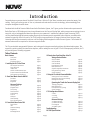
DURATION PER DAY (HOURS) 8 6 4 3 2 1
SOUND LEVEL (dB) 90 93 95 97 100 103
THIS SYMBOL IS INTENDED TO ALERT THE USER TO THE PRESENCE
OF NON-INSULATED "DANGEROUS VOLTAGE" WITHIN THE
PRODUCT'S ENCLOSURE THAT MAY BE OF SUFFICIENT MAGNITUDE
TO CONSTITUTE A RISK OF ELECTRIC SHOCK TO PERSONS.
THIS SYMBOL IS INTENDED TO ALERT THE USER TO THE PRESENCE
OF IMPORTANT OPERATING AND MAINTENANCE (SERVICING)
INSTRUCTIONS IN THE LITERATURE ACCOMPANYING THE UNIT.
1. Read all safety and operating instructions before using this
product.
2. All safety and operating instructions should be kept for future
reference.
3. Read and understand all warnings listed on the operating
instructions.
4 . Follow all operating instructions to operate this product.
5. This product should not be used near water, i.e. Bathtub,
sink,swimming pool, wet basement, etc.
6. Only use dry cloth to clean this product.
7. Do not block any ventilation openings, It should not be placed flat
against a wall or placed in a built-in enclosure that will impede the
flow of cooling air.
8. Do not install this product near any heat sources ;such
as,radiators, heat registers, stove or other apparatus (including
heat producing amplifiers) that produce heat.
9. Do not defeat the safety purpose of the polarized or grounding-
type plug. A polarized plug has two blades with one wider than the
0ther.A grounding-type plug has two blades and a third grounding
prong. The wide blade or the third prong are provided for your
safety If the provided plug does not fit into your outlet, consult an
electrician for replacement of the obsolete outlet.
10. Protect the power cord being walked on or pinched, particularly at
Plugs, convenience receptacles and the point where they exit
from the apparatus. Do not break the ground pin of the power
supply cord.
11 . Only use attachments specified by the manufacturer.
12. Use only with the cart, stand, tripod, bracket, or table specified by
the manufacturer or sold with the apparatus. When a cart is used,
use caution when moving cart/apparatus combination to avoid
injury from tip-over.
13. Unplug this apparatus during lightning storms or when unused for
long periods of time.
14. Care should be taken so that objects do not fall and liquids are
not spilled into the unit through the ventilation ports or any other
openings.
15. Refer all servicing to qualified service personnel. Servicing is
required when the apparatus has been damaged in any way;
such as, power-supply cord or plug is damaged, liquid has been
spilled or objects have fallen into the apparatus, the apparatus
has been exposed to rain or moisture, does not operate normally
or has been dropped.
16. WARNING: To reduce the risk of fire or electric shock, do not
expose this apparatus to rain or moisture.
IMPORTANT SAFETY INSTRUCTIONS
RISK OF ELECTRIC SHOCK
DO NOT OPEN
CAUTION: TO REDUCE THE RISK OF ELECTRIC SHOCK, DO
NOT REMOVE CHASSIS. NO USER-SERVICEABLE
PARTS INSIDE. REFER SERVICING TO QUALIFIED
SERVICE PERSONNEL.
AVIS: RISQUE DE CHOC ELECTRIQUE-NE PAS OUVRIR.
CAUTION
APPARATUS SHALL NOT BE EXPOSED TO DRIPPING OR SPLASHING
AND THAT NO OBJECTS FILLED WITH LIQUIDS, SUCH AS VASES,
SHALL BE PLACED ON THE APPARATUS.
Page 1

FRENCH
DURE EN HEURES PAR JOUR 8 6 4 3 2 1
INIVEAU SONORE CONTINU EN dB 90 93 95 97 100 103
Danger
L‘exposition a des niveaux eleves de bruit peut provoquer une perte
permanente de l’audition, Chaque organisme humain reagit
differemment quant a la perte de l’audition, mais quasiment tout le
monde subit une diminution de I’acuite auditive lors d’une exposition
suffisamment longue au bruit intense. Les autorites competentes en
reglementation de bruit ont defini les expositions tolerees aux niveaux
de bruits:
Selon les autorites, toute exposition dans les limites citees ci-dessus,
peuvent provoquer certaines pertes d’audition. Des bouchons ou
protections dans l’appareil auditif ou sur l’oreille doivent etre portes lors
de l’utilisation de ce systeme d’amplification afin de prevenir le risque
de perte permanente de l’audition, Dans le cas d’expositions
superieures aux limites precitees il est recommande, afin de se
premunir contre les expositions aux pressions acoustiquese I evees
potentielIement dangeure u ses, aux personnes exposees aux
equipements capables de delivrer de telles puissances, tels ce
systeme d’amplification en fonctionnement, de proteger l’appareil
auditif.
ATTENTION: AFIN DE LlMlTER LE RISQUE DE CHO ELECTR/QUE, NE
PAS ENLEVER LE CHASSIS. NE CONTIENT PAS DE
PIECES POUVANT ETRE REPAREE PAR L’UTILISATEUR.
CONFER LE SERVICE APRES-VENTE AUX
REPARATEURS
ATTENTION
RISQUE DE CHOC ELECTRIQUE
NE PAS OUVRIR.
CE SYMBOLE A POUR BUT D'AVERTIR L'UTILISATEUR DE LA PRESENCE
DE VOLTAGE DANGEREUX NON-ISOLE A L'INTERIEUR DE CE PRODUIT
QUI PEUT ETRE DE PUISSANCE SUFFISAMMENT IMPORTANTE POUR
PROVOQUER UN CHOC ELECTRIQUE AUX PERSONNES.
CE SYMBOLE A POUR BUT D'AVERTIR L'UTILISATEUR DE LA PRESENCE
D'INSTRUCTIONS D'UTILISATION ET DE MAINTENANCE DANS LES
DOCUMENTS FOURNIS AVEC CE PRODUIT.
IMPORTANTES INSTRUCTIONS DE SECURITE
1. Lire avec attention toutes les recommandations et précautions
d'emploi avant d'utiliser ce produit.
2. Toutes les recommandations et précautions d'emploi doivent être
conservées afin de pouvoir s'y reporter si nécessaire.
3. Lire et comprendre tous les avertissements énumérés dans les
précautions d'emploi.
4. Suivre toutes les précautions d'emploi pour utiliser ce produit.
5. Ce produit ne doit pas être utilisé près d'eau, comme par exemple
baignoires, éviers, piscine, sous-sol humides ... Etc.
6. Utiliser exclusivement un chiffon sec pour nettoyer ce produit.
7. Ne bloquér aucune ouverture de ventilation. Ne pas placer le
produit tout contre un mur ou dans une enceinte fernée, cela
gênerait le flux d'air nécessaire au refroidissement.
8. Ne pas placer le produit près de toute source de chaeur telle que
radiateurs, arrivées d'air chaud, fourneaux ou autres appareils
générant de la chaleur (incluant les amplificateurs producteurs
de chaleur) .
9. Ne pas négliger la sécurité que procure un branchement polarisé
ou avec raccordement à la terre, Un branchement polarisé
comprend deux fiches dont l'une est plus large que l'autre. Un
branchement à la terre comprend deux fiches plus une troisième
reliée à la terre. Si la fiche secteur fournie ne s'insert pas dans
votre prise de courant. consulter un 'électricien afin de remplacer
votre prise obsolète.
10. Protéger le cordon d'alimentation de tout écrasement ou
pincement, particulièrement au niveau des fiches, des
réceptacles utilisés et à l'endroit de sortie de l'appareil. Ne pas
casser la fiche de terre du cordon d'alimentation.
11. Utiliser uniquement les accessoires spécifiés par le constructeur.
12. Utiliser uniquement avec le chariot de transport, le support, le
trépied, la console ou la table spécifiés par le constructeur ou
vendus avec l'appareil. Lors de l'utilisation d'un chariot, bouger
avec précaution l'ensemble chariotlappareil afin d'éviter les
dommages d'un renversement.
13 Débrancher cet appareil lors d'orages ou s'il n'est pas utilisé
pendant une longue période.
14. Des précautions doivent être prises afin qu'aucun objet ne tombe
et qu'aucun liquide ne se répande à l'intérieur de l'appareil par
les orifics de ventilation ou n'importe quelle autre ouverture.
15. Pour toutes interventions techniques s'adresser à un technicien
qualifié.L'intervention technique est nécessaire lorsque l'appareil
a été endommagé de n'importe quelle façon, comme par
exemple si le cordon secteur ou sa fiche sont détériorés,si du
liquide a coulé ou si des objets sont tombés à l'intérieur de
l'apparei1,si l'appareil a été exposé à la pluie ou à l'humidité, s'il
ne fonctionne pas normalement ou s'il est tombé.
16. ATTENTI0N:Pour réduire le risque d'incendie ou de choc
electrique ne pas exposer l'appareil à la pluie ou à l'humidité.
AFIN DE REDUIRE LES RISQUÉ D'INCENDIE ET DE DECHARGE
ELECTRIQUE, NE PAS EXPOSER CET APPAREIL A LA PLUIE OU A
L'HUMIDITE.
Page 2

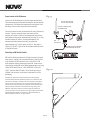
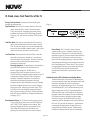
GROUND
CLAMPS
GROUND
CLAMPS
ELECTRIC
SERVICE
ENTRANCE
ELECTRIC
SERVICE
ENTRANCE
ANTENNA
DISCHARGE UNIT
NEC SECTION
810-20
GROUNDING
CONDUCTORS
ANTENNA
DISCHARGE UNIT
NEC SECTION
810-20
GROUNDING
CONDUCTORS
GROUND CLAMPSGROUND CLAMPS
POWER SERVICE
GROUPING ELECTRODE
SYSTEM NEC ART 250
PART H
POWER SERVICE
GROUPING ELECTRODE
SYSTEM NEC ART 250
PART H
NEC NATIONAL ELECTRICAL CODE NEC NATIONAL ELECTRICAL CODE
ANTENNA
LEAD-IN
WIRE
ANTENNA
LEAD-IN
WIRE
Page 3

Congratulations on your purchase of the NuVo T2 dual Tuner. With the T2 Dual Tuner, broadcast music enters the twenty-first
century. Finally you can enjoy state-of-the-art, advanced radio and satellite receiver technology, with astonishingly clear
reception throughout the entire home.
Combined with the NuVo Concerto Whole Home Audio Distribution System, the T2 gives you the ultimate radio experience with
Radio Data Service. RDS displays artist and song information on the Concerto Display Pads, which means no more waiting to hear a
song title, only to be disappointed when the station cuts to a commercial. Interference Adaptive Signal Processing (IASP)
circuitry combined with NuVo’s patent pending Remote Active Antenna provide remarkable radio reception, even when radio
stations are typically difficult to receive. The T2 XM satellite tuner provides the full range of stations direct into your home.
Listening selections are streamed in real time to all the Display Pads throughout the NuVo Concerto System. The included XM
antenna makes satellite reception for the home easy and reliable.
The T2 is packed with many powerful features, and is designed to integrate seamlessly with any distributed audio system. This
manual is a guide to making the installation complete, and for making the most of your T2 Tuner. When properly installed, the T2
will provide years of listening enjoyment.
Introduction
Table of Contents:
Basic Features
Front Panel page 6
Back Panel page 7
RC3 Remote Control page 8
I. Installing the NV-T2 Dual Tuner
Stereo Audio Conncetions page 9
Direct IR Control page 9
IR Pass-Thru page 10
AM/FM and XM Antenna Input page 11
Proper Location of the XM Antenna page 12
Subscribing to the XM Service page 12
II. Front Panel Menu Controls AM/FM
Exit Menu page 13
Force Mono page 13
Brightness page 13
Advanced Settings
Operating Mode page 14
Regional Setup page 14
Fine-Tuning page 14
Seek Threshold page 14
Audio Settings page 15
Auto-On page 15
AUX Input page 16
Noise Blanking page 16
Rs232 Communication page 16
III. Front Panel Menu Control XM
Signal Status page 17
Info page 17
Advanced Settings page 17
Diagnostics page 17
XM Display Button page 17
IV. Stand-alone Front Panel Use of the T2
Tuning a Desired Station
Step Tune Mode page 18
Seek Tune Mode page 18
Scan Tune Mode page 18
Direct Numeric Tuning page 18
Radio Data Service page 18
Signal Strength/Stereo Indicator page 19
Using the Memory Feature page 19
Source Switching page 19
V. Using the T2 with the Concerto NuVoNet
Setting Up the Tuner for NuVoNet page 20
Making Sure Your Concerto Is Ready page 20
Making the Connection page 21
Operating the T2 with the Concerto Display Pad
Tuning by Categories page 21
Radio Data Service page 21
Direct Numeric Entry Tuning page 21
Source Switching page 21
V. T2 Configuration Software
1.0 Start page 22
2.0 Config page 22
3.0 Presets page 23
Advanced Settings
4.0 Advanced Config page 24
5.0 Advanced Presets page 26
6.0 Categories page 26
7.0 Update System page 27
Troubleshooting page 28
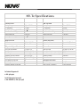
NV-T2DF Specifications page 30
Page 4

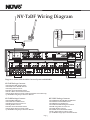
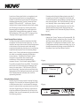
NV-T2DF Wiring Diagram
Diagram is shown with the NuVo Concerto System and NuVoNet.
NV-T2DF Package Contents:
1 NV-T2DF Dual AM, FM, WX Tuner
1 NV-T2FAA Active AM/FM Antenna
1 NV-T2RC3 Remote Control
2 NV-RCA1 Stereo RCA Audio Cables
1 NV-AC1 2 Meter Coaxial Antenna Cable
1 NV-PC2 North American Power Cable (North American model only)
1 pr. NV-REM1U Single Space Rack Ear Mounts
NV-T2DX Package Contents
1 NV-T2DX Dual XM Tuner
1 NV-T2XAA Active XM Antenna
1 NV-FBC F-Type Barrel Connector
1 NV-RC3 Remote Control
2 NV-RCA1 Stereo RCA Audio Cables
1 NV-PC2 North American Power Cable
1 pr. NV-REM1U Single Space Rack Ear Mounts
Page 5
L
L
OUTAUX IN
R
R
TRIGGER
ON=+12V
AUDIO
OUTPUT
TUNER B TUNER A
OUT
AUDIO
OUTPUT
RS 232
ANTENNA INPUT
IN
USE ONLY NuVo
NV-T2PAS
POWERED ANTENNA SYSTEM
TRIGGER
ON=+12V
AUX IN
Model NV-T2DF
Dual XM Tuner
NuVo Techonlogies LLC•
Cincinnati Ohio USA
www.nuvotechnologies.com
3033118
T
R
E
E
T
K
N
I
CM
T
R
E
E
T
K
N
I
SYSTEM
SYS ON
EXT. MUTE
SYSTEM
ZONE TRIGGER OUTPUTS
SOURCE LINK
L
R
L
R
L
R
SOURCE INPUTS
NETWORK
SUM1
EMITTER OUTPUTS
3033118
C
US
RR
CONFORMS TO
UL STD.6500
CERTIFIED TO
CAN/CSA STD.E60065
NuVo Technologies Cincinnati Ohio USA
FUSE:T5 A
120V 60Hz 500W
MODEL NV-I8M
SIX SOURCE EIGHT ZONE
AUDIO DISTRIBUTION SYSTEM
www.nuvotechnologies.com
DIGITAL LINK
TIP=L
RING=R
ZONE 2
VARIABLE
OUTPUT
FIXED
OUTPUT
TIP=L
RING=R
VARIABLE
OUTPUT
FIXED
OUTPUT
TIP=L
RING=R
VARIABLE
OUTPUT
FIXED
OUTPUT
TIP=L
RING=R
VARIABLE
OUTPUT
FIXED
OUTPUT
TIP=L
RING=R
VARIABLE
OUTPUT
FIXED
OUTPUT
TIP=L
RING=R
VAR.
OUT
FIX.
OUT
PROGRAM
1 2 3 4 5
6
1 2 3 4 5
6
1 2 3
4
1 2 31 2 3
4
CONNECT TO
NV-I8X
USE NV-SLC1
CABLE
CONNECT TO
NV-I8X
USE NV-SLC1
CABLE
CONNECT TO
NV-I8EZP1
USE NV-NC1
CABLE
USE CNLY WITH 250V FUSE
4
5
6
SUM2
5
6
5 6 7
8
IR PASS-THRU
IR INPUT
NuVoNet
MENU
LOCK
DIM
HOTKEY
MASTER
SEEK
TUNE
SCAN
CATEGORY
R S T
P E ET/DIR
EC
DND
POWER
VOLUME
1
4
7
+10
FM
A
M
W
X
XM
2
5
8
0
3
6
9
EN
T
MU
TE
MENU
PLAY
UC
SORE
SYSTEM ON
DO NOT DISTURB
ZONE 1
VARIABLE
OUTPUT
FIXED
OUTPUT
SPEAKER
40W/6 OHMS X 2
LEFT RIGHT
ZONE 3
ZONE 4
ZONE 5
ZONE 6
ZONE 7
ZONE 8
SOURCE STATUS
RS 232
SPEAKER
40W/6 OHMS X 2
LEFT RIGHT
SPEAKER
40W/6 OHMS X 2
LEFT RIGHT
SPEAKER
40W/6 OHMS X 2
LEFT RIGHT
SPEAKER
40W/6 OHMS X 2
LEFT RIGHT
SPEAKER
40W/6 OHMS X 2
LEFT RIGHT
NV-T2DFX Package Contents
1 NV-T2DFX Dual AM/FM/WX and XM Tuner
1 NV-T2FAA Active AM/FM Antenna
1 NV-T2XAA Active XM Antenna
1 NV-T2AAC AM/FM/XM Signal Combiner
1 NN-FBC F-Type Barrel Connector
1 NV-T2RC3 Remote Control
2 NV-T2RCA1 Stereo RCA Audio Cables
1 NV-PC2 North American Power Cable
1 pr. NV-REM1U Single Space Rack Ear Mounts
AM/FM
ANTENNA IN
XM
ANTENNA IN
COMBINED
ANTENNA OUT
NV-T2FXC SINGNAL
COMBINER

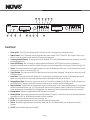
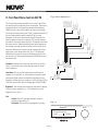
Front Panel
1. Stand-by LED: This LED (Light Emitting Diode) indicates that the T2 is plugged into an AC power source.
2. Remote Sensor: This IR (Infrared) receiver allows wireless remote control of the T2 functions. This IR input is active, even
when it is used in conjunction with the direct IR input on the back panel.
3. Frequency and Band Display: The display indicates the band AM, FM, or WX (Weatherband)and station frequency, or the XM
station being received.
4. Preset/ RDS Display: This is a display of customized preset information, or RDS (Radio Data Service) information
transmitted with the station's broadcast. NuVoNet allows this to scroll automatically on the Concerto Display Pads (pg. 20).
5. Stereo: This indicates whether the FM signal reception is stereo. No display indicates mono. The T2 software allows an FM
station preset to be set in mono mode (pg. 23).
6. Signal Strength: This indicates the level of signal being received at the tuned frequency. The signal level refers only to AM
or FM band signals.
7. Select Knob: Turning the knob scrolls through the T2 menu options; pressing the knob selects the displayed menu option.
When not in menu mode, the Select knob tunes up and down. Pushing the knob selects the station.
8. Category Up and Down: This function requires the use of the T2 installation software for AM/FM use. The XM categories are
predefined by XM. Categories allow station selection to be set up according to specific listening genres.
9. Numeric Buttons: These buttons are programmable for direct station preset access. Customized alphanumeric strings can be
defined in the setup software (pg. 23). They can also be used for direct frequency tuning for AM/FM or XM station tuning.
These custom strings are displayed on the Display Pads of an integrated Concerto system whenever a preset is accessed.
10. Display Button: This button toggles between RDS information on and off.
11. Memory Button: The memory button provides you with a personal “notepad” to store and recall artist and song information
originating from RDS or XM data being broadcast for future reference.
12. Menu: This button enters and exits the menu mode (pg. 14).
13. Pre/Dir: This toggles between numeric preset selection and direct station input.
14. Source: This button toggles between the available modes, AM, FM, WX (Weather Band), Aux or XM input on the XM
versions.
15. On/Off: Turns each individual tuner on and off.
Model NV-T2DF
Dual FM/AM/WX Tuner
REMOTE
SENSOR
PUSH TO
ENTER
SELECT
1
6
2
7
3
8
4
9
5
0
<
<
DISPLAY MEMORY MENU PRE/DIR SOURCE ON-OFF
CATEGORY
PRESET/DIRECT
Tuner B Tuner A
STANDBY
1
6
2
7
3
8
4
9
5
0
<
<
DISPLAY MEMORY MENU PRE/DIR SOURCE ON-OFF
CATEGORY
PRESET/DIRECT
PUSH TO
ENTER
SELECT
FM 94.1
Classic Rock
AM 550
Stereo
FM STEREO•AM•WEATHER
FM STEREO•AM•WEATHER
1
2
3
4
5
6
7
8
9
10
11
12
13
14
15
-
–-
–
---
-
-
-
–
–
–
–-
-
–-
–
---
-
-
-
–
–
–
–-
Page 6

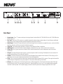
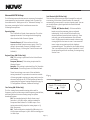
Back Panel
1. Antenna Input: Coax “F” connector brings in the signal input from the NuVo NV-T2FAA AM/FM or the NV-T2XAA XM active
antenna (pg. 11).
2. Aux. Input: This stereo RCA connector is enabled through the advanced menu options (pg. 14), and allows an additional
audio source to be connected and accessed through the tuner source selection.
3. Audio Output: A Stereo RCA output allows the tuner audio signal to be connected to an amplifier source, such as the NuVo
Simplese, Essentia, and Concerto audio distribution systems.
4. Trigger ON: This voltage output provides a constant 12 volts when the Tuner is turned on.
5. Audio Output: This is a second stereo output designed to work with a tip, ring, sleeve 3.5mm stereo connection.
6. IR Pass-Thru: This 3.5mm connection is used to link IR control between two or more components used in the same
installation.
7. IR Input: The single IR Input accepts a mono 3.5mm mono patch cable for receiving IR information from an external IR
receiver without the use of an external IR emitter.
8. NuVoNet : This RJ45 connection is used with one of the Peripheral Device inputs on the Concerto EZ Port (see pg. 20) to
enable direct one-to-one communication with the Concerto Display Pads.
10. RS232: This 9-pin DB9 connection allows serial communication with an external RS232 system. This may also be used for
downloading a configuration from your computer to the internal flash memory of the tuner.
11. AC Power: This connects the T2 with an AC power source. When plugged into a live AC outlet the blue power LED (Light
Emitting Diode) on the T2's front panel will remain lit. When neither tuner is on, the T2 is in standby mode and draws
less than 2 watts of power. The T2 power supply is universal and will operate at a voltage range from 110V to 240V.
L
OUTAUX IN
R
TRIGGER
ON=+12V
AUDIO
OUTPUT
TUNER B TUNER A
L
OUT
R
AUDIO
OUTPUT
IR PASS-THRU
IR INPUT
NuVoNet
ANTENNA INPUT
IN
SYSTEM
USE ONLY NuVo
NV-T2PAS
POWERED ANTENNA SYSTEM
TRIGGER
ON=+12V
AUX IN
Model NV-T2FX
FM/AM/WX-XM Tuner
NuVo Techonlogies LLC•
Cincinnati Ohio USA
www.nuvotechnologies.com
MADE IN CHINA
3033118
T
R
E
E
T
K
N
I
T
R
E
E
T
K
N
I
CM
90~264V 50~60Hz 15W
RS 232
1
2
3
4
5
6
7
8
9
10
Page 7

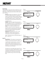
NV-T2RC3 Remote Control
1. Power: The power button turns the selected tuner on and off.
2. Scroll Buttons: These buttons are the equivalent of turning the front panel Select knob. The top button is the equivalent of
turning the knob clockwise, and the bottom button is the equivalent of counterclockwise.
3. Enter: This button is the equivalent of pushing the Select knob on the front panel (see Front Panel #7).
4. Seek Up and Down: The seek buttons will tune to the next available station with the required signal strength for AM and FM
use. The signal threshold can be adjusted higher or lower using the T2 Configurator software (see pg. 25), or through the
advanced menu options on the front panel (see pg. 14).
5. Tune Up and Down: The tune function steps through each station frequency regardless of the frequency signal strength.
6. Category Up and Down: The category buttons step through each of the defined genre categories. Categories must be defined
in the advanced settings of the T2 Configurator software for AM/FM use (see pg. 26).
7. Pre/Dir: The T2 allows up to 10 preset stations in each of up to 10 preset banks. This button scrolls through each of the
defined banks and then to direct tuning. In direct tuning, you can use the numeric buttons to access a specific station
frequency or XM channel number. Presets are selected by a single push of numeric button 0-9.
8. Tuner A & B LED: This LED glows red when Tuner A is selected and green when Tuner B is selected. This LED glows only
momentarily when a button is pushed.
9. Tuner Selector: This button toggles between Tuner A and Tuner B operation.
10. Scan: The scan button tunes up to the next station with a signal strength above the programmed threshold for AM and FM or
to the next XM channel and waits 5 seconds before automatically tuning to the next station. This uses the same signal level as
the seek function.
11. Numeric Buttons: These buttons (0-9) are used to access a specific station frequency or choose a pre-defined station preset.
12. ENT: This button duplicates the enter function of the Enter button #3.
13. Source Buttons: These four buttons select each of the four available audio sources within the T2.
1
2
3
4
5
6
7
8
9
0
ENT
AM
FM
WX
AUX
SCAN
ENTER
PWR
A/B
HOLD
ALL OFF
PRE
SEEK
TUNE
CATEGORY
T2 Tuner
REMOTE CONTROL
DIR
TUNER
1
2
3
4
5
6
7
8
9
10
11
12
13
Page 8

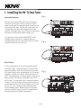
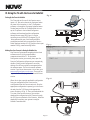
I. Installing the NV-T2 Dual Tuner
Stereo Audio Connections
Each tuner has two audio output jacks. One is a stereo RCA
connection, and the other is a stereo 3.5mm mini. The RCA
output is an individual left and right channel connection made
with a standard RCA cable. The other end is connected to the
corresponding audio input on the back panel of the audio
amplifier. An example of this is one of the source inputs on the
back panel of a NuV0 audio distribution system, fig. 1.
The 3.5mm stereo output labeled “AUDIO OUTPUT” is also
available for system connection. Compatible cables are
available with the male mini connection on each end, or with a
stereo RCA connection on one end, fig. 2.
L
L
OUTAUX IN
R
R
TUNER B TUNER A
OUT
AUDIO
OUTPUT
AUDIO
OUTPUT
ANTENNA INPUT
IN
USE ONLY NuVo
NV-T2PAS
POWERED ANTENNA SYSTEM
TRIGGER
ON=+12V
TRIGGER
ON=+12V
AUX IN
SOURCE LINK
L
R
L
R
L
R
SOURCE INPUTS
TIP=L
RING=R
ZONE 2
VARIABLE
OUTPUT
FIXED
OUTPUT
TIP=L
RING=R
VARIABLE
OUTPUT
FIXED
OUTPUT
TIP=L
RING=R
VARIABLE
OUTPUT
FIXED
OUTPUT
TIP=L
RING=R
12 34 5
6
12 34 5
6
123
4
CONNECT TO
NV-I8X
USE NV-SLC1
CABLE
5
6
ZONE 1
VARIABLE
OUTPUT
FIXED
OUTPUT
SPEAKER
40W/6 OHMSX 2
LEFT RIGHT
ZONE 3
ZONE 4
SOURCE STATUS
SPEAKER
40W/6 OHMSX 2
LEFT RIGHT
SPEAKER
40W/6 OHMSX 2
LEFT RIGHT
Fig.1
Fig. 2
Fig. 3
L
L
OUTAUXIN
R
R
TUNER B TUNER A
OUT
AUDIO
OUTPUT
AUDIO
OUTPUT
ANTENNA INPUT
IN
USE ONLY NuVo
NV-T2PAS
POWERED ANTENNA SYSTEM
TRIGGER
ON=+12V
TRIGGER
ON=+12V
AUX IN
SOURCE LINK
L
R
L
R
L
R
SOURCE INPUTS
TIP=L
RING=R
ZONE 2
VARIABLE
OUTPUT
FIXED
OUTPUT
TIP=L
RING=R
VARIABLE
OUTPUT
FIXED
OUTPUT
TIP=L
RING=R
VARIABLE
OUTPUT
FIXED
OUTPUT
TIP=L
RING=R
12 34 5
6
12 34 5
6
123
4
CONNECT TO
NV-I8X
USE NV-SLC1
CABLE
5
6
ZONE 1
VARIABLE
OUTPUT
FIXED
OUTPUT
SPEAKER
40W/6 OHMSX 2
LEFT RIGHT
ZONE 3
ZONE 4
SOURCE STATUS
SPEAKER
40W/6 OHMSX 2
LEFT RIGHT
SPEAKER
40W/6 OHMSX 2
LEFT RIGHT
Direct IR Control
The T2 is designed for IR control via IR received by an audio
distribution system. In the NuVo Simplese or Essentia audio
distribution systems, the IR emitter outputs act as a repeater
to IR signals incident on the system keypads. The T2's wired IR
connector is a 3.5mm two-conductor (mono) jack labeled “IR
INPUT.” Using a mono mini-to-mini patch cable, connect the IR
emitter output of a Simplese or Essentia Main Unit to the IR
INPUT on the T2. The two tuners in the T2 respond to separate
IR codes, so the direct IR input replaces the need for external
IR emitters placed over the IR receiver windows on the front of
the unit, fig. 3. This connection is not used when using the
Concerto NuVoNet system. The NuVo Essentia and Simplese
systems are used for example, but the T2 is compatible with
any audio system that is capable of repeating IR.
RS 232
Model NV-T2DF
Dual XMTuner
NuVo Techonlogies LLC•
Cincinnati OhioUSA
www.nuvotechnologies.com
3033118
I
N
T
E
R
T
E
K
CM
I
N
T
E
R
T
E
K
SYS ON
EXT. MUTE
SYSTEM
ZONE TRIGGER OUTPUTS
NETWORK
SUM1
EMITTER OUTPUTS
3033118
C
US
R
CONFORMS TO
UL STD.6500
CERTIFIED TO
CAN/CSASTD.E60065
NuVoTechnologies CincinnatiOhio USA
FUSE:T5A
120V 60Hz 500W
MODEL NV-I8M
SIXSOURCE EIGHT ZONE
AUDIODISTRIBUTION SYSTEM
www.nuvotechnologies.com
DIGITAL LINK
VAR IABL E
OUTPUT
FIXED
OUTPUT
TIP=L
RING=R
VARIABLE
OUTPUT
FIXED
OUTPUT
TIP=L
RING=R
VAR.
OUT
FIX.
OUT
PROGRAM
123
4
123
CONNECT TO
NV-I8X
USE NV-SLC1
CABLE
CONNECT TO
NV-I8EZP1
USE NV-NC1
CABLE
USE CNLYWITH 250V FUSE
4
5
6
SUM2
567
8
IR PASS-THRU
IR INPUT
NuVoNet
ZONE 5
ZONE 6
ZONE 7
ZONE 8
RS 232
SPEAKER
40W/6 OHMSX 2
LEFT RIGHT
SPEAKER
40W/6 OHMSX 2
LEFT RIGHT
SPEAKER
40W/6 OHMSX 2
LEFT RIGHT
Page 9

IR Pass-Thru
The mini jack labeled “IR pass-thru" mini connection is
used for connecting forwarded IR signals to an audio
component connected to the auxiliary audio input.
Using the Aux. Input
The T2 is equipped with an auxiliary audio input labeled
“AUX IN.” This will accept an audio signal from an external
component. This is most useful as an additional local
source, or an additional source in a multi-zone audio
system.
The auxiliary input is a stereo RCA connection and
requires a standard RCA cable for the connection, fig. 4.
This must be enabled through the advanced menu, which
is accessed through the “Select Knob” on the face of the
T2 (see Menu Controls, AUX Input pg. 14) or in the T2
Configurator software (see Using the T2 Configurator
Software pg. 22). An additional advanced feature is the
ability to set the gain of the auxiliary signal to match the
output signal level of the T2.
Once the auxiliary input is enabled, it is selected from the
remote using the “AUX” button, fig. 5, or by pressing the
“Source” button for either Tuner A or Tuner B on the face
of the T2 and stepping through FM, AM, and WX (Weather
Band) to Aux. On the XM models the source button simply
toggles between XM reception and the auxiliary input,
fig. 6.
L
L
OUTAUX IN
R
R
TUNER B TUNER A
OUT
AUDIO
OUTPUT
AUDIO
OUTPUT
ANTENNA INPUT
IN
USE ONLY NuVo
NV-T2PAS
POWERED ANTENNA SYSTEM
TRIGGER
ON=+12V
TRIGGER
ON=+12V
AUX IN
Auxiliary
Audio Source
Audio
Out
Fig . 4
Fig . 5
Fig . 6
1
2
3
4
5
6
7
8
9
0
ENT
AM
FM
WX
AUX
SCAN
ENTER
PWR
A/B
HOLD
ALL OFF
PRE
SEEK
TUNE
CATEGORY
T2 Tuner
REMOTE CONTROL
DIR
TUNER
Model NV-T2DF
Dual FM/AM/WX Tuner
REMOTE
SENSOR
PUSH TO
ENTER
SELECT
1
6
2
7
3
8
4
9
5
0
<
<
DISPLAY MEMORY MENU PRE/DIR SOURCE ON-OFF
CATEGORY
PRESET/DIRECT
Tuner A
STANDBY
FM STEREO•AM•WEATHER
Aux Input
Page 10

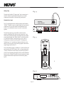
AM/FM Antenna Input
The T2 ships with a proprietary active AM/FM antenna. This
antenna is designed to work only with the NuVo T2 series
AM/FM tuners. It can be located up to 200 feet from the tuner
location, and we recommend 75-ohm RG 6 coaxial cable with a
standard F style connector on each end. Simply attach the
cable to the connector at the bottom of the antenna, and into
the “Antenna Input” on the T2, fig. 7. Once connected, the T2
should immediately receive broadcast signals and RDS (Radio
Data Service) when it is available.
We recommend placing the antenna inside in an attic or as
high as possible for the best possible AM and FM reception,
fig. 8. A 2 meter (6 foot) pre-terminated coaxial cable is
provided with the tuner package for testing the antenna
connection or if you choose to place the antenna close to the
tuner location.
L
L
OUTAUX IN
R
R
TRIGGER
ON=+12V
AUDIO
OUTPUT
TUNER B TUNER A
OUT
AUDIO
OUTPUT
ANTENNA INPUT
IN
USE ONLY NuVo
NV-T2PAS
POWERED ANTENNA SYSTEM
TRIGGER
ON=+12V
AUX IN
Fig . 7
Fig . 8
Page 11
The NuVo amplified
antenna can be located
up to 200 feet from the
T2 Tuner.
XM Antenna Input
The proprietary active XM antenna shipped with the XM model
tuners is connected in the same way as the AM/FM antenna. A
single run of RG6 coaxial cable is necessary for the signal for
both XM tuners in the case of the dual XM model or AM/FM and
XM model. For best performance it is best to use a good quality
quad-sheilded cable.
The AM/FM and XM model tuner requires the use of the NV-
AAC signal combiner to bring both the AM/FM and XM signals
to the tuner, fig. 9.

Page 12
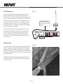
Proper Location of the XM Antenna
Location of the XM antenna is critical to proper performance.
There cannot be any obstructions between the antenna and the
southern sky. This means that any possible interference from
buildings, trees or other structures must be avoided.
The most common location is mounted to the eve of the home’s
exterior. If you are using the eve as the location of the
antenna, be careful to locate it low enough that the roof over
hang does not obstruct the antenna from clear sky, fig. 10. Any
outside location will suffice. For best performance, the
antenna should be mounted vertically, and placed at
approximately a 45° angle. Again, see fig. 10. This angle is
closer to 50°or 60° if you are in the extreme southern portion
of the United States.
Subscribing to XM Satellite Radio®
XM Satellite Radio provides over 150 digital channels of music,
news, sports, comedy, talk, and entertainment, with all of the
music channels 100% commercial free. Each of the T2 XM
tuner modules require a subscription from XM. Listeners can
subscribe by visiting XM on the Web at www.xmradio.com or by
calling XM’s Listener Care at 1-800-XMRADIO (1-800-967-
2346). Have the Radio ID ready. This is found by tuning to
channel 0 on the tuner, on the tuner’s back panel or on the
packaging.
Hardware and required basic monthly subscription sold separately.
Premium Channel available at additional monthly cost. Installation costs
and other fees and taxes, including a one-time activation fee may apply.
Subscription fee is consumer only. All fees and programming subject to
change. Channels with frequent explicit language are indicated with an XL.
Channel blocking is available for XM radio receivers by calling 1-800-
XMRADIO. Subscriptions subject to Customer Agreement available at
xmradio.com. XM service only available in the 48 contiguous United States.
XM and XM Satellite Radio® are trademarks of XM Satellite Radio Inc.
©2005 XM Satellite Radio Inc. All rights reserved.
Fig . 9
Fig . 10
L
L
OUTAUX IN
AUX IN
R
R
TRIGGER
ON=+12V
AUDIO
OUTPUT
TUNER B TUNER A
AUDIO OUT
AUDIO
OUTPUT
ANTENNA INPUT
IN
USE ONLY NuVo
NV-T2PAS
POWERED ANTENNA SYSTEM
TRIGGER
ON=+12V
AM/FM
ANTENNA IN
XM
ANTENNA IN
COMBINED
ANTENNA OUT
NV-T2FXC SINGNAL
COMBINER
For XM reception the RG6
cable between the tuner,
Use any commercially
available barrel
The
connection
NV-T2FX Dual AM/FM/
Weather Band and XM

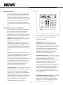
II. Front Panel Menu Controls AM/FM
The T2 has many settings available in the menus. This allows
for specialized set up options for tuner operation. The menu is
accessed from the front panel by pressing and holding the
“MENU” button. Once in menu mode, you can scroll through
the menu options by turning the “Select” knob clockwise (CW)
to move forward and counterclockwise (CCW) to move
backward. As the Select knob moves through the menu, the
choices appear on that tuner's display. The top line contains
the name of the current menu selection. The bottom line shows
the menu choices. When the desired menu option appears on
the display, pressing the Select knob enters the menu choice.
When the desired menu setting is made, pressing the Select
knob saves it (see menu option tree, fig. 11.) Pressing the
MENU button once while you are in the menu options moves
you up one level. Pressing and holding the MENU button exits
the menu mode.
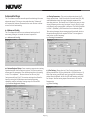
Exit Menu: When you first enter the menu choices, the first
choice is to exit the menu, which takes you back to normal
turner operation.
Force Mono: This is a useful feature when a stereo pair of
speakers is not available, or if the signal of a station is weak.
Forcing the signal to mono eliminates a weak station from
flipping in and out of stereo reception. If RDS display is OFF or
if there is no valid RDS data, the display will indicate “MONO.”
Brightness: This changes the intensity of each tuner's display.
The level choices range from 1- 8. The default level is the
brightest level 8, fig 11.
Info:
Version: This tells you what firmware version is
currently loaded on the T2.
Test Status: This is for factory diagnostic use only.
Fig. 11 Menu Option Tree
PUSH TO
ENTER
SELECT
Tuner A
Brightness:
Low _____ High
FM STEREO•AM•WEATHER
Fig. 12
Page 13
Menu
Exit Menu
Force Mono
Brightness
Signal Status (XM only)
Adv. Settings
Info
(LOW to HIGH, 8 steps)
Version x.xx
Test Status (factory use only)
(previous menu)
Operating Mode
Regional Setup
Fine Tuning
Seek Threshold
Audio Settings
Auto-ON
AUX Input
(previous menu)
Concerto Src 1
Concerto Src 2
Concerto Src 3
Concerto Src 4
Concerto Src 5
Concerto Src 6
Stand-alone
(previous menu)
USA
Western Europe
Australia
New Zealand
Custom
(previous menu)
Disabled
Enabled
(previous menu)
FM Threshold
AM Threshold
Weather
(previous menu)
Bass
Treble
Balance
Output Level
(previous menu)
Disabled
Enabled
(previous menu)
Disabled
Enabled
Set AUX Gain
(previous menu)
Signal Strength
Antenna
Sat.1
Sat. 2
Terrestrial

The following menu selections are not necessary for standard
tuner operation, but do provide a deeper level of control for
those who need it. When you scroll to “Advanced Settings” in
the menu, pressing the Select knob then accesses the
following menu options:
Operating Mode
The T2 defaults to Stand-alone operation. This is the
appropriate mode if it is being used with anything
other than the NuVo Concerto System.
Concerto Source 1-6: This must be set for the
appropriate NuVo Concerto source input, if the T2 is
going to be used with Concerto's NuVoNet control
network (see pg. 20 Using the T2 with Concerto and
NuVoNet).
Regional Setup (AM/FM Use Only)
USA: This setting is optimized for the United States
and Canada.
European (Western): This setting is optimized for
Western Europe.
Australia: This setting is optimized for all of Australia.
New Zealand: This setting covers all of New Zealand.
These four settings cover most of the worldwide
tuning standards. For operation in countries outside
of these geographic regions, you may need to use the
advanced settings in the T2 Configurator software for
customizing the regional tuning standard (see pg. 24
T2 Configuration Software, Advanced Settings).
Fine-Tuning (AM/FM Use Only)
The fine-tuning feature enables tuning with a smaller
frequency step to include more station frequency possibilities,
which may be used in areas allowing many low-power
broadcast stations.
FM: The standard tuning for North America and
Australia is .200 MHz steps, and the standard for
Europe and New Zealand is .100 MHz steps. Fine-
tuning automatically drops the tuning steps to .05
MHz increments.
AM: The North America standard for AM tuning is in
10 kHz steps and Europe is 9 kHz. AM fine tuning goes
in 1 kHz steps.
Advanced AM/FM Settings
Seek Threshold (AM/FM Use Only)
This sets the effective station signal strength for seek and
scan tuning. With either of these modes, the tuner will
automatically tune up until it receives a good signal. You can
set the definition a good signal with the seek threshold
feature, fig. 13.
FM, AM, WX (Weather Band): All three available
bands are set the same way, but are adjusted
individually. Scroll with the Select knob to the
desired band and press the knob to select it. Once
selected, you can choose between five different
levels. High means the station needs to have a very
strong signal for the tuner to react. Low causes the
tuner to stop at any station with the slightest
measurable signal. The default is the middle setting.
This is an adjustment of the signal threshold. It sets
the minimum signal level necessary for tuning using
Seek or Scan.
PUSH TO
ENTER
SELECT
Tuner A
Seek Threshold:
Low _____ High
FM STEREO•AM•WEATHER
Fig. 13
Page 14

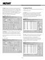
Audio Settings
These selections are intended for AM, FM and XM stand-alone
applications. They should be left at default settings for NuVo
audio systems. These systems allow identical audio control on
a per-zone basis.
Bass EQ: Bass output can be adjusted +12 dB or down
to 12 dB. The default setting is flat. This feature is
useful for stand-alone use with an amplifier that does
not have bass EQ control. If you are using the T2 with a
NuVo audio distribution system, or another system
that allows for EQ control, you should leave the T2 set
at 0 dB (flat), fig 14.
Treble EQ: Treble can be adjusted the same as bass.
The level ranges from 12 dB to +12 dB and defaults at 0
dB. As with the bass setting, this should not be used
unless there is no external EQ capability, fig. 15.
Balance: Left and Right channel output can be
adjusted if desired. As with the EQ adjustments, this
feature should not be used when the T2 is used with
an audio system that already has EQ and balance
adjustment capability, fig. 16.
Output Level: The signal level from the T2 can be
adjusted up or down to match the input gain
characteristics of other audio equipment in the
system. The default setting is 0 dB and the range is 6
dB to +12 dB, fig. 17.
Auto-ON
Enable/Disable: The T2 can be set to turn the tuner
displays on automatically when power is applied. This
is a good feature for stand-alone use. In the event of
a power outage or anytime AC power is lost and
restored, the T2 tuners will automatically turn back on
with the last-used settings without having to use the
ON/OFF button on the front panel.
This selection is not necessary when using the T2 with
the NuVo Concerto system, because the built-in power
management system between the T2 and Concerto will
automatically turn on the tuners when the Power
button is pressed on any of the Concerto's Display
Pads.
Fig. 14
Fig. 15
Fig. 16
Fig. 17
PUSH TO
ENTER
SELECT
Tuner A
Bass EQ:
Bass EQ +4 dB
FM STEREO•AM•WEATHER
PUSH TO
ENTER
SELECT
Tuner A
Treble EQ:
Treble EQ +6 dB
FM STEREO•AM•WEATHER
PUSH TO
ENTER
SELECT
Tuner A
Balance:
L------x------R
FM STEREO•AM•WEATHER
PUSH TO
ENTER
SELECT
Tuner A
Output Level:
Output +3 dB
FM STEREO•AM•WEATHER
Page 15

AUX Input
Disable/Enable: The T2 has an auxiliary audio input
that allows access through either of the tuners to an
additional audio source. To use this you must first
enable the input in the menu options.
AUX Gain: The audio input from an auxiliary source
can be adjusted to match the output of the T2's Tuner
A and Tuner B. AUX Gain is selected by using the Select
knob to scroll to that choice and press to enter. Once
AUX Gain is selected, amount of input up and down is
then controlled and set by using the Select knob to
adjust up or down, and then pressing the knob when
the desired gain setting has been reached, fig. 18.
Noise Blanking
Disable/Enable: This is an AM/FM function. The T2
default setting is to have noise blanking (partial to
complete muting of weak noise signals) Enabled. For
areas of T2 operation having a very low interference
level, it may be desirable to select this menu item and
set Disabled in order to listen to very distant, weak
stations.
PUSH TO
ENTER
SELECT
Tuner A
Aux Gain Set:
Output +5 dB
FM STEREO•AM•WEATHER
Fig. 18
Page 16
RS232 Communication
The T2 has a serial communication port. This allows for
complete control of the T2 functions by RS232 control devices.
The necessary protocol for this control is available through the
NuVo Website Prozone at
. www.nuvotechnologies.com/prozone

Page 17
III. Front Panel Menu Controls XM
Most menu functions are identical to the AM/FM tuner with
some exceptions. The menu functions specific to XM reception
are outlined here.
Signal Status: This function is important to XM signal
reception. When the antenna is installed and plugged into the
T2 antenna input, follow the following submenus. These are
designed to insure that the antenna location is sufficient for
good signal reception.
Antenna: This display will either indicate OK or None.
OK means the tuner is detecting the presence of an
antenna.
Signal Strength: There are four displays for this
selection. They are none, weak, marg. , and good. You
want to adjust the antenna location so the display
indicates good reception.
Sat. 1: This indicates the percentage of error from the
first satellite. As long as the signal strength is good,
this should be between 90 and 100%.
Sat 2: This function is identical to Sat 1 and indicates
the percentage of error for the second satellite.
Terrestrial: Many areas have terrestrial signal
repeaters to boost the satellite signal. This is useful
where a satellite signal might be impeded. This menu
function shows the % of error in the terrestrial signal.
If the satellite signal is good, the terrestrial signal is
not necessary.
Info: Version: This tells you what firmware version is
currently loaded on the T2.
Test Status: This is for factory diagnostic use only.
Advanced Settings: Diagnostics is the only XM function not
included in the AM/FM choices. This is an XM customer service
function. Typically you do not have to do anything with this
selection. If you have a question about XM operation the XM
customer service representative may ask for the information
on the diagnostic display.
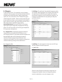
XM Display Button
The front panel control is identical for AM/FM and XM with the
exception of the Display button. Each push of the Display
button toggles through four display choices. The top line of
the display always shows the XM channel choice and channel
name.
Name/Title: This is the default setting and displays
the name of the artist or talk show host and title of
the song or show being broadcast, fig. 19.
Name: This display shows the name of the artist or
show host being broadcast, fig.20.
Title: This displays only the title of the song or show
being broadcast, fig. 21.
Category: This shows the channel’s genre category as
defined by XM, fig. 22.
PUSH TO
ENTER
SELECT
Tuner A
XM50 The Loft
Cold Play/Clocks
XM SATELLITE RADIO
PUSH TO
ENTER
SELECT
Tuner A
XM50 THE LOFT
COLD PLAY
XM SATELLITE RADIO
PUSH TO
ENTER
SELECT
Tuner A
XM50 The Loft
Clocks
XM SATELLITE RADIO
PUSH TO
ENTER
SELECT
Tuner A
XM50 The Loft
Acoustic Rock
XM SATELLITE RADIO
Fig. 19
Fig. 20
Fig. 21
Fig. 22

IV. Stand-alone Front Panel Use of the T2
Tuning a Desired channel: Pressing the Select knob cycles
through the tuning modes.
Step Tune Mode: Each of the T2's tuners default to step tune
mode. When the Select knob is turned clockwise
(CW), the tuner will tune within the preset tuning
standard (see Advanced AM/FM Settings, Regional
Setup, pg. 14), and counter clockwise (CCW) to tune
down.
Seek Tune Mode: The seek tunes up when the Select knob is
turned CW and down when the Select knob is turned
CCW. In seek tune mode, the tuner will automatically
stop at the next available channel signal. It will stay at
that selection until you tune to a new channel.
Scan Tune Mode: Scan tune works like Seek Tune, except the
tuner will only stay on a channel for 5 seconds and
then continue to the next signal. To retain a selection,
press the Select knob before the tuner resumes
scanning for frequencies.
Tuning by Categories: A unique feature is the ability to
group AM/FM frequencies or XM channels into
specific genre categories. The XM service
automatically allows for genre selection, but for
AM/FM use these categories must be defined in the T2
configurator software (see NV-T2DF Configurator
software, Assigning Categories). Once you have
decided on the categories you want to use and
assigned specific station frequencies, you will always
have that template for future use. To enter Category
tuning, press the “Category up or down keys.” This
will scroll to the next assigned category with each
push. When a category is selected, turning the Select
knob will step through all the frequencies within that
category, fig.23.
Direct Numeric Tuning: The T2 allows for direct numeric entry.
To get to the Direct mode, press the PRE/DIR button
until “DIRECT TUNE” appears on the display. Then
pressing the numeric buttons in sequence for the
desired AM/FM frequency or XM channel and
pressing the Select knob will tune to that channel.
Fig. 23
Model NV-T2DF
Dual FM/AM/WX Tuner
REMOTE
SENSOR
PUSH TO
ENTER
SELECT
1
6
2
7
3
8
4
9
5
0
<
<
DISPLAY MEMORY MENU PRE/DIR SOURCE ON-OFF
CATEGORY
PRESET/DIRECT
Tuner A
STANDBY
FM STEREO•AM•WEATHER
104.7
Classic Rock
Page 18
Preset Tuning: The T2 is able to store 10 preset
stations in each of up to 10 banks of presets. This
allows a total of 100 presets. The factory default is
two banks of presets, but more banks can be added or
deleted in the T2 Configurator software. Saving a
preset is done simply by tuning to a desired station
and pressing and holding one of the numeric buttons
until the display reads “Preset Saved.” Once a preset
is saved, banks of presets are accessed by pressing
the PRE/DIR button, and then pressing the
appropriate number button accesses the desired
preset.
Radio Data Service (RDS) Information and Display Modes
The Radio Data Service is a format FM broadcasters
can use to send artist and song information with their
broadcast. Although this service is gaining in
popularity, all stations do not yet use it. If a station
is broadcasting RDS, the T2 will automatically scroll
what is being received. The Program Status Name
(PSN) data field (up to 8 characters) will appear in
the upper right of the display. This was intended by
RDS system architects to display a station name,
such as a call sign. The Radiotext field (up to 64
characters) will be displayed on the second line and
will scroll if it exceeds 16 characters. The Radiotext
message will be displayed on Display Pads in an
integrated Nuvo Concerto system. Radiotext was
intended for display of artist and title information.

Actual use of these data fields is not regulated, and
they may vary significantly in content between
stations. If you choose not to have RDS information
displayed, pressing the “Display” button will then
indicate “RDS receive OFF”. In this state, Stereo
indication and a signal strength indicator will replace
the PSN field on the top line, and only the station
frequency will be displayed on a connected zone's
Display Pad. Pressing the button again will restore
RDS and display “RDS receive ON.” Each press of the
“Display” button toggles between on and off.
Signal Strength/Stereo Indicator
The signal strength indicator responds to the field
strength of the received carrier signal, fig. 24. This
indicator has seven discrete levels, with a single point
at the bottom of the character space indicating a
signal just detectable by the tuner, and a very strong
signal indicated by four lines of increasing length
above 3 dots. Stereo indication is also provided when
the tuner is successfully decoding FM Multiplex
stereo stations. The field will be blank if stereo
reception is not possible due to weak signal
conditions or if the station is broadcasting in
monaural (mono). The field will display MONO if
Force Mono is enabled from the MENU. This indicator
and Stereo lock information will be displayed upon
tuning to a new station. If RDS Receive is ON (see
previous section), then the indicator and Stereo lock
information will be displayed momentarily until valid
RDS PSN data has been received; then it will be
replaced by that data.
Using the Memory Feature
Memory is used to store a specific display for future
reference. This is useful for referencing specific RDS
or XM information later. It can be used for viewing a
song title and artist that you might need to recall at a
later date. By pressing the “Memory” button with a
single tap, whatever information is scrolling on the
display at that time will automatically be saved in the
first memory position.
PUSH TO
ENTER
SELECT
Tuner A
102.7 Stereo
WXYZ
FM STEREO•AM•WEATHER
-
–-
–
---
-
-
-
–
–
–
–-
Fig.24
Fig. 25
Model NV-T2DF
Dual FM/AM/WX Tuner
REMOTE
SENSOR
PUSH TO
ENTER
SELECT
1
6
2
7
3
8
4
9
5
0
<
<
DISPLAY MEMORY MENU PRE/DIR SOURCE ON-OFF
CATEGORY
PRESET/DIRECT
Tuner A
STANDBY
FM STEREO•AM•WEATHER
102.7 Rockin
Display Saved
Page 19
Pressing and holding the Memory button puts the T2
in memory recall mode. Turning the Select knob will
scroll up through the saved displays, starting with the
most recently saved. The T2 has the ability to save up
to 10 displays. When a new display is saved, it will
automatically place that information in the first slot,
and bump all previously saved displays down one.
Display number 10 will automatically drop off the list,
fig. 25.
Source Switching
Pushing the “Source” button scrolls between AM, FM,
WX (Weather Band), and Auxiliary (Aux.) modes. The
auxiliary mode is optional and must be turned on
through the T2 Configuration software (see NV-T2DF
Configuration software, advanced settings, pg. 24) or
through the advanced settings menu accessed at the
front panel (see Front Panel Menu Controls).
La page est en cours de chargement...
La page est en cours de chargement...
La page est en cours de chargement...
La page est en cours de chargement...
La page est en cours de chargement...
La page est en cours de chargement...
La page est en cours de chargement...
La page est en cours de chargement...
La page est en cours de chargement...
La page est en cours de chargement...
La page est en cours de chargement...
La page est en cours de chargement...
-
 1
1
-
 2
2
-
 3
3
-
 4
4
-
 5
5
-
 6
6
-
 7
7
-
 8
8
-
 9
9
-
 10
10
-
 11
11
-
 12
12
-
 13
13
-
 14
14
-
 15
15
-
 16
16
-
 17
17
-
 18
18
-
 19
19
-
 20
20
-
 21
21
-
 22
22
-
 23
23
-
 24
24
-
 25
25
-
 26
26
-
 27
27
-
 28
28
-
 29
29
-
 30
30
-
 31
31
-
 32
32


Nuvo NV-T2 Guide d'installation
- Catégorie
- Équipement musical supplémentaire
- Taper
- Guide d'installation
dans d''autres langues
- English: Nuvo NV-T2 Installation guide
Documents connexes
-
Nuvo NV-I8GMS Manuel utilisateur
-
-
-
-
-
-
-
-
-
Nuvo Concerto NV-I8DMS Manuel utilisateur
