Aigis Mechtronics HS9303 Series Installation And Operating Instructions Manual
- Catégorie
- Boîtiers de caméra
- Taper
- Installation And Operating Instructions Manual

I NSTALLATION AND O PERATING I N STRUCTIONS
Corner Security Housings
HS9303 SERIES

1. Read Instructions - All the safety and operating instructions should be read before
the unit is operated.
2. Retain Instructions - The safety and operating instructions should be retained for
future reference.
3. Heed Warnings - All warnings on the unit and in the operating instructions should
be adhered to.
4. Follow Instructions - All operating and use instructions should be followed.
5. Cleaning - Unplug the unit from the outlet before cleaning. Do not use liquid
cleaners or aerosol cleaners. Use a damp cloth for cleaning.
6. Attachments - Do not use attachments not recommended by the product
manufacturer as they may cause hazards.
7. Accessories - Do not place this unit on an unstable stand, tripod, bracket, or
mount. The unit may fall, causing serious injury to a person and serious
damage to the unit. Use only with a stand, tripod, bracket, or mount
recommended by the manufacturer or sold with the product. Any mounting of the
unit should follow the manufacturer's instructions and should use a
mounting accessory recommended by the manufacturer.
An appliance and cart combination should be moved with care. Quick
stops, excessive force, and uneven surfaces may cause the appliance and
cart combination to overturn.
8. Ventilation - Openings in the enclosure, if any, are provided for ventilation, to
ensure reliable operation of the unit, and to protect it from overheating. These
openings must not be blocked or covered. This unit should not be placed in a
built-in installation unless proper ventilation is provided or the manufacturer's
instructions have been adhered to.
9. Power Sources - This unit should be operated only from the type of power source
indicated on the marking label. If you are not sure of the type of power supply you
plan to use, consult your appliance dealer or local power company. For units
intended to operate from battery power or other sources, refer to the operating
instructions.
10. Grounding or Polarization - This unit may be equipped with a polarized
alternating-current line plug (a plug having one blade wider than the other). This
plug will fit into the power outlet only one way. This is a safety feature. If you are
unable to insert the plug fully into the outlet, try reversing the plug. If the plug
should still fail to fit, contact your electrician to replace your obsolete outlet. Do
not defeat the safety purpose of the polarized plug.
Alternately, this unit may be equipped with a 3-wire grounding-type plug, a plug
having a third (grounding) pin. This plug will only fit into a grounding-type power
outlet. This is a safety feature. If you are unable to insert the plug into the outlet,
contact your electrician to replace your obsolete outlet. Do not defeat the safety
purpose of the grounding-type plug.
11. Power Cord Protection - Power supply cords should be routed so that they are not
likely to be walked on or pinched by items placed upon or against them, paying
particular attention to cords and plugs, convenience receptacles, and the point
where they exit from the appliance.
12. Power Lines - An outdoor system should not be located in the vicinity of overhead
power lines or other electric light or power circuits or where it can fall into such
power lines or circuits. When installing an outdoor system, extreme care should be
taken to keep from touching such power lines or circuits as contact with them might be
fatal. U.S.A. models only - refer to the National Electrical Code Article 820 regarding
installation of CATV systems.
13. Overloading - Do not overload outlets and extension cords as this can result in
a risk of fire or electric shock.
14. Object and Liquid Entry - Never push objects of any kind into this unit through
openings, as they may touch dangerous voltage points or short out parts that could
result in a fire or electric shock. Never spill liquid of any kind on the unit.
15. Servicing - Do not attempt to service this unit yourself as opening or removing covers
may expose you to dangerous voltage or other hazards. Refer all servicing to qualified
service personnel.
16. Damage Requiring Service - Unplug the unit from the outlet and refer servicing to
qualified service personnel under the following conditions:
a. When the power supply cord or plug is damaged.
b. If liquid has been spilled or objects have fallen into the unit.
c. If the unit has been exposed to rain or water.
d. If the unit does not operate normally by following the operating instructions.
Adjust only those controls that are covered by the operating instructions, as an
improper adjustment of other controls may result in damage and will often require
extensive work by a qualified technician to restore the unit to its normal operation.
e. If the unit has been dropped or the cabinet has been damaged.
f. When the unit exhibits a distinct change in performance--this indicates a need for
service.
17. Replacement Parts - When replacement parts are required, be sure the service
technician has used replacement parts specified by the manufacturer or have the same
characteristics as the original part. Unauthorized substitutions may result in fire,
electric shock, or other hazards.
18. Safety Check - Upon completion of any service or repairs to this unit, ask the service
technician to perform safety checks to determine that the unit is in
proper operating condition.
19. Coax Grounding - If an outside cable system is connected to the unit, be sure the cable
system is grounded. U.S.A. models only--Section 810 of the National Electrical Code,
ANSI/NFPA No.70-1981, provides information with respect to proper grounding of the
mount and supporting structure, grounding of the coax to a discharge unit, size of
grounding conductors, location of discharge unit, connection to grounding electrodes,
and requirements for the grounding
electrode.
20. Lightning - For added protection of this unit during a lightning storm, or when it is left
unattended and unused for long periods of time, unplug it from the wall outlet and
disconnect the cable system. This will prevent damage to the unit due to lightning and
power line surges.
IMPORTANT SAFEGUARDS
The lightning flash with an arrowhead symbol within an equilateral triangle
is intended to alert the user to the presence of uninsulated "dangerous
voltage" within the product's enclosure that may be of sufficient magnitude
to constitute a risk of electric shock to persons.
CAUTION: TO REDUCE RISK OF ELECTRICAL SHOCK, DO NOT OPEN COVERS. NO USER
SERVICEABLE PARTS INSIDE. REFER SERVICING TO QUALIFIED SERVICE PERSONNEL.
The exclamation point within an equilateral triangle is intended to alert the
user to presence of important operating and maintenance (servicing)
instructions in the literature accompanying the appliance.
SAFETY PRECAUTIONS:
This label may appear on the bottom of the unit due to space limitations.
L'éclair fléché dans un triangle équilatéral, avertit l'utilisateur de la
présence d'une "tension dangereuse" non isolée à l'intérieur de l'appareil
et d'une valeur suffisante pour constituer un risque d'électrocution.
Le point d'exclamation contenu dans un triangle équilatéral, avertit
l'utilisateur de la présence, dans la documentation qui accompagne
l'appareil, de consignes d'utilisation et de maintenance importantes.
SECURITE: En raison de limitation de place, cette étiquette peut être placée sur
le dessous de l'appareil.
DANGER: POUR ÉVITER TOUT RISQUE D'ÉLECTROCUTION, NE PAS OUVRIR LE BOÎTIER.
IL N'Y A PAS DE PIÈCES REMPLAÇABLES À L'INTÉRIEUR. POUR TOUTE RÉVISION,
S'ADRESSER À UN TECHNICIEN SPÉCIALISÉ.
VORSICHT: UM EINEN ELEKTRISCHEN SCHLAG ZU VERMEIDEN, ABDECKUNG NICHT
ENTFERNEN. WARTUNGEN ALLER ART QUALIFIZIERTEM PERSONAL ÜBERLASSEN.
PRECAUCION: PARA REDUCIR EL RIESGO DE CHOQUE ELÉCTRICO, FAVOR NO ABRIR LA
CUBIERTA. ESTE EQUIPO NO CONSTA DE PIEZAS O PARTES QUE REQUIEREN SERVICIO O
MANTENIMIENTO. PARA REPARACIONES FAVOR REFERIRSE A UN TÉCNICO CALIFICADO.
SICHERHEITSVORKEHRUNGEN: Aus Platzgründen kann diese Warnung auf
der Unterseite des Gerätes angebracht sein.
Das Blitzsymbol im gleichseitigen Dreieck soll den Benutzer auf nicht isolierte
"Hochspannung" im Gehäuse aufmerksam machen, die eventuell stark genug
ist, um einen elektrischen Schlag zu verursachen.
Das Ausrufezeichen im gleichseitigen Dreieck soll den Benutzer auf wichtige
Bedienungs- und Wartungsanleitungen in der dem Gerät beigefügten Literatur
aufmerksam machen.
El símbolo representado por un relámpago con punta de flecha dentro de
un triángulo equilátero, se muestra con el objetivo de alertar al usuario
que existen "voltages peligrosos" sin aislamiento, dentro de la cubierta de
la unidad. Dichos voltages pueden ser de tal magnitud que constituyen un
riesgo de choque eléctrico a personas.
El símbolo de exclamación dentro de un triángulo equilátero, se muestra
con el objetivo de alertar al ususario de que instrucciones de operación y
mantenimiento importantes acompañan al equipo.
PRECAUCIONES DE SEGURIDAD: Debido a limitaciones de espacio, esta
etiqueta puede aparecer en la parte inferior de la unidad.

3
CONTENTS
1 UNPACKING . . . . . . . . . . . . . . . . . . . . . . . . . . . . . . . . . . . . .3
2 SERVICE . . . . . . . . . . . . . . . . . . . . . . . . . . . . . . . . . . . . . . . .3
3 CARE AND MAINTENANCE . . . . . . . . . . . . . . . . . . . . . . . . .3
4 DESCRIPTION . . . . . . . . . . . . . . . . . . . . . . . . . . . . . . . . . . . .3
5 INSTALLATION . . . . . . . . . . . . . . . . . . . . . . . . . . . . . . . . . . .4
5.1 Accessories . . . . . . . . . . . . . . . . . . . . . . . . . . . . . . . . . . . . . .4
5.2 Disassembly . . . . . . . . . . . . . . . . . . . . . . . . . . . . . . . . . . . . . .4
5.3 Mounting the Unit . . . . . . . . . . . . . . . . . . . . . . . . . . . . . . . . .5
5.4 Camera/Lens Installation . . . . . . . . . . . . . . . . . . . . . . . . . . . . .6
5.5 Final Assembly . . . . . . . . . . . . . . . . . . . . . . . . . . . . . . . . . . . .6
1 UNPACKING
Unpack carefully. This is electro-mechanical equipment and should
be handled with care.
Check for the following items:
• Model number of unit.
• Installation and Operating Instructions.
If an item appears to have been damaged in shipment, replace it
properly in its carton and notify the shipper. If any items are miss-
ing, notify Aigis Mechtronics.
The shipping carton is the safest container in which the unit may
be transported. Save it for possible future use.
2 SERVICE
If the unit ever needs repair service, the customer should contact
Aigis Mectronics for return authorization and shipping instruc-
tions,
1-800-523-6500.
3 CARE AND MAINTENANCE
There are no moving parts in this unit. Regularly scheduled main-
tenance will help prolong the operation life of this unit. Clean the
viewing window as needed with a mild, non-abrasive detergent in
water and a soft cloth.
4DESCRIPTION
The HS9303 Series are inside corner mounted security housings
designed for applications such as prisons, parking garages, and
hospitals. These housings are ideal for any application requiring
secure CCTV monitoring.
For maximum protection and durability, the light weight cast alu-
minum design of the HS9303 Series housings provide the strength
of 12 gage steel with the superior strength-to-weight ratio of alu-
minum. The standard viewing window is constructed of 9.5 mm
(0.37 in) clear polycarbonate material, treated with a scratch-resis-
tant coating A removable bottom panel provides access to the
camera and is secured using two tamper-resistant screws. A spe-
cial tool is provided for screw removal.
Attractively styled, these housings are furnished without a full top
cover and are designed to be corner mounted flush with the ceil-
ing. Adding the optional Top Cover (not included) allows the
housing to be mounted below the ceiling line. Other options
include: a key lock on the access panel; a tinted 9.5 mm (0.37 in)
viewing window; and a clear 12.7 mm (0.50 in) viewing window.
Corner Security Housings
HS9303 Series
Instructions for Use
WARNING:
To prevent fire or shock hazards, do not expose
this unit or power supply to rain or moisture.

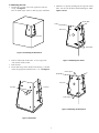
Access Panel
Tamperproof Screw
Tamperproof Screw
Figure 1: Removing Access Panel
4
5 INSTALLATION
This installation should be made by qualified service personnel and
conform to the National Electrical Code and applicable local
codes.
5.1 Accessories
HS9313: Sloped top cover for housings mounted below the ceil-
ing line.
Defogger kits are recommended for use in areas where condensa-
tion could cause fogging of the viewing window.
HS9313-6: 115 VAC, 50/60 Hz, 50 W thermostatically controlled
defogger kit.
HS9313-2: 24 VAC, 50/60 Hz, 50 W thermostatically controlled
defogger kit.
HS9313-5: 230 VAC, 50/60 Hz, 50 W thermostatically controlled
defogger kit.
Do Not Exceed 30 VAC Input on 24 VAC models. Operation above
30 VAC violates low voltage operation (Class 2 Specifications).
Normal operation is 24 VAC.
Maximum Camera/Lens Size: Housing accepts camera/lens combi-
nations up to 267L x 102W x 76H mm (10.5 x 4.0 x 3.0 in) when
using 1/4-inch, 1/3-inch and 1/2-inch format CCD cameras.
Dimensions include standard connectors.
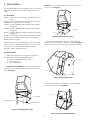
5.2 Disassembly
1. Remove the hardware kit from the outside of the housing.
The hardware kit should contain the following items:
(1) 1/4-20 x 1/2" Button Head Flange Screw
(1) Tamperproof Tool
(2) Keys (-L Models only)
2.
All Models Except HS9303L: Use the special tool provided
to unscrew the front two tamperproof screws. Remove the access
panel.
See Figure 1.
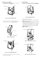
Figure 2: Removing Access Panel
HS9303L: Use the key provided to unscrew the lock. Remove the
access panel. See Figure 2.
Figure 4: Removing the Mount System
Figure 3: Removing the Cover
Access Panel
Key
Lock
Rear Panel
Cover
Mount System
Rear Panel
Flange Nuts
3. Reach into the housing and remove the six flange nuts that
attach the cover to the rear panel. Remove the cover. See Figure 3.
Note: Do not lose these parts. They will be needed in reassembly.
4. Unscrew the 2 flange nuts and remove the camera mounting
system from the rear panel. See Figure 4.

5
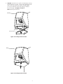
5.3Mounting the Unit
1. Position the rear panel in the corner against the walls and
ceiling. See Figure 5.
Note: A smooth square surface is ideal for proper installation.
Figure 5: Positioning the Rear Panel
2. Mark the wall for bolt anchor holes. At least eight 8 mm
(5/16 in) bolts will be needed.
3. Drill the holes.
4. Decide how wiring will be routed into the housing. If needed,
remove the appropriate knockout (PG21 - 1 in).
See Figure 6.
Figure 6: Knockouts
5. Mount the rear panel by installing only the right side anchor
bolts. Start the left side bolts, but DO NOT tighten. See
Figures 7 and 8
.
Figure 7: Mounting Rear Panel
Figure 8: Mounting the Rear Panel
Rear Panel
Knockout
Knockout
Rear Panel
Anchor Bolts
Anchor Bolts
Do Not Tighten
Rear Panel
Do Not Tighten

6
5.4 Camera/Lens Installation
1. Reattach the camera mounting system to the rear panel using
two 6 mm flange nuts. See Figure 9.
Figure 9: Securing the Mount System
2. Secure the camera to the camera mount using one 1/4-20 x
1/2" button head flange screw. See Figure 10 and 11.
Figure 10: Camera Mount
5.5 Final Assembly
1. Mount the cover by aligning the studs with the slots on the
rear panel. Secure using the six flange nuts. See Figure 12.
Figure 12: Replacing the Cover
2. Tighten the left side anchor bolts.
3. Make final adjustments to the camera and camera mounting
system.
4.
All Models Except HS9303L: Attach the access panel to the
housing by inserting the latch into the rear panel. Screw the
two tamperproof screws down tight to the cover. If the rear of
the access panel is not tight remove access panel and lower
the latch by rotating it clockwise. Repeat until tight.
See
Figures 13 and 14
.
Note: Retain special tool for future use.
Figure 13: Inserting the Access Panel
Figure 11: Camera and Mount System
3. Make all electrical connections to the camera. See individual
camera and lens instructions.
Figure 14: Securing the Access Panel
Mount System
Flange Nuts
Rear Panel
Camera
Camera Mount
1/4-20 x 1/2" Button
Head Flange Screw
Camera
Mounting System
Cove
r
Latch
Rear Panel
Access Panel

7
4. HS9303L: Attach the access panel to the housing by inserting
the latch into the rear panel. Screw the lock down tight to the
cover. If the rear of the access panel is not tight remove
access panel and lower the latch by rotating it clockwise.
Repeat until tight.
See Figures 15 and 16.
Note: Retain key for future use.
Figure 15: Inserting the Access Panel
Figure 16: Securing the Access Panel
Rear Panel
Access Panel
Latch

100 0028 001 AIG 10/02
Printed in U.S.A.
©2002 Aigis Mechtronics
1124 Louise Road, Winston-Salem, NC 27107-5450
Tel: 336.785.7740 Fax: 336.785.7744
Data subject to change without notice
-
 1
1
-
 2
2
-
 3
3
-
 4
4
-
 5
5
-
 6
6
-
 7
7
-
 8
8


Aigis Mechtronics HS9303 Series Installation And Operating Instructions Manual
- Catégorie
- Boîtiers de caméra
- Taper
- Installation And Operating Instructions Manual
dans d''autres langues
- English: Aigis Mechtronics HS9303 Series
Autres documents
-
Sanyo VSE-2300 Manuel utilisateur
-
Philips LTC 9405 Manuel utilisateur
-
-
SsangYong NEW CHAIRMAN Le manuel du propriétaire
-
Mazda mx-5 2016 Manuel utilisateur
-
Pelco ExSite Enhanced Fixed Sery Guide d'installation
-
Bosch Appliances UHI-SBG-0 Manuel utilisateur
-
-
Moog Videolarm PFH10C8WY Mode d'emploi