Haier AD12MS1ERAD Operating Manual And Instructions
- Catégorie
- Climatiseurs split-system
- Taper
- Operating Manual And Instructions

No.0150513771 E
Polski
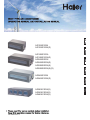
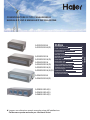
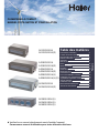
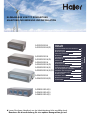
AD24MS1ERA
AD24MS1ERA(D)
AD28NS1ERA(S)
AD36NS1ERA(S)
AD48NS1ERA(S)
AD12MS1ERA
AD12MS1ERA(D)
AD18MS1ERA
AD18MS1ERA(D)
AD24MS2ERA
AD24MS2ERA(D)
AD28MS2ERA(S)
AD28MS2ERA(S)(D)


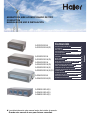
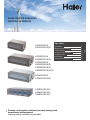
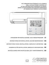
DUCT TYPE AIR CONDITIONER
OPERATION MANUAL AND INSTALLATION MANUAL
Contents
Please read this manual carefully before installation.
Keep this operation manual for future reference.
English
Cautions
Safety Precautions
Parts and Functions
Operation
Installation Manual For Wire Controller
Heating Mode
Care and Maintenance
Troubleshooting
Precaution for Installation
Is The Unit Installed Correctly
Installation Procedure
3
4
7
10
14
15
16
17
20
21
22
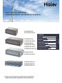
AD24MS1ERA
AD24MS1ERA(D)
AD28NS1ERA(S)
AD36NS1ERA(S)
AD48NS1ERA(S)
AD12MS1ERA
AD12MS1ERA(D)
AD18MS1ERA
AD18MS1ERA(D)
AD24MS2ERA
AD24MS2ERA(D)
AD28MS2ERA(S)
AD28MS2ERA(S)(D)

CE
All the products are in conformity with the following
European provision:
-Low voltage Directive
-Electomagnetic CompatibilitY
ROHS
Your air conditioning product is marked with this
symbol.This means that electrical and electronic
products shall not be mixed with unsorted
household waste.Do not try to dismantle the
system yourself:the dismantling of the air
conditioning system,treatment of the refrigerant,of oil and of
other part must be done by a qualified installer in accordance
with relevant local and national legislation.Air conditioners
must be treated at a specialized treatment facility for reuse,
recycling and recovery.By ensuring this product is disposed
of correctly,you will help to prevent potential negative cons-
equences for the environment and humen health.Please
contact the installer or local authority for more information.
Battery must be removed from the remote controller and dis-
posed of separately in accordance with relevant local and
nationl legislation.
The products are fulfilled with the requirements in the
council on the Restriction of the use of Certain Hazardous
Substances in Electrical and Electronic Equipment(EU
RoHS Directive)
WEEE
In accordance with the directive 2012/19/EU of the European
parliament,herewith we inform the consumer about the dis-
posal requirements of the electrical and electronic products.
DISPOSAL REQUIREMENTS:
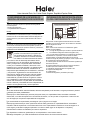
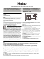
Contains fluorinated greenhouse gases
covered by the Kyoto Protocol
This product contains fluorinated greenhouse gases covered
by the Kyoto Protocol.Do not vent into the atmosphere.
Refrigerant type:R410A
GWP=global warming potential
Please fill in with indelible ink,
1 the factory refrigerant charge of the product
2 the additional refrigerant amount charged in the field
and
1+2 the total refrigerant charge
on the refrigerant charge label supplied with the product.
The filled out label muset be adhered in the proximity of the
product charging port(e.g.onto the inside of the stop value
cover).
A contains fluorinated greenhouse gases covered by the
Kyoto Protocol
B fatory refrigerant charge of the product:see unit name
plate
C additional refrigerant amount charged in the field
D total refrigerant charge
E outdoor unit
F refrigerant cylinder and manifold for charging
Haier Industrial Park, No.1 Haier road, Qingdao,P.R.China
A
B
C
D
kg
kg
kg
R410A
WARNING
If the supply cord is damaged, it must be replaced by the manufacturer, its service agent or similarly qualified persons in
order to avoid a hazard.
This appliance is not intended for use by persons (including children) with reduced physical, sensory or mental capabilities,
or lack of experience and knowledge, unless they have been given supervision or instruction concerning use of the appliance
by a person responsible for their safety.
Children should be supervised to ensure that they do not play with the appliance.
This appliance can be used by children aged from 8 years and above and persons with reduced physical, sensory or
mental capabilities or lack of experience and knowledge if they have been given supervision or instruction concerning use
of the appliance in a safe way and understand the hazards involved. Children shall not play with the appliance. Cleaning
and user maintenance shall not be made by children without supervision.
The appliances are not intended to be operated by means of an external timer or separate remote-control system.
Keep the appliance and its cord out of reach of children less than 8 years.
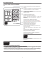
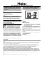
EUROPEAN REGULATIONS
CONFORMITY FOR THE MODELS
IMPORTANT INFORMATION REGA-
RDING THE REFRIGERANT USED
2011/65/EU
directive of the European parliament and of
GWP:2088

3
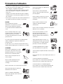
Cautions
Disposal of the old air conditioner
Before disposing an old air conditioner that goes out of use, please make sure it's inoperative and safe. Unplug the air conditioner
in order to avoid the risk of child entrapment.
It must be noticed that air conditioner system contains refrigerants, which require specialized waste disposal. The valuable
materials contained in a air conditioner can be recycled. Contact your local waste disposal center for proper disposal of an old
air conditioner and contact your local authority or your dealer if you have any question. Please ensure that the pipework of your
air conditioner does not get damaged prior to being picked up by the relevant waste disposal center, and contribute to environmental
awareness by insisting on an appropriate, anti-pollution method of disposal.
Disposal of the packaging of your new air conditioner
All the packaging materials employed in the package of your new air conditioner may be disposed without any danger to the
environment.
The cardboard box may be broken or cut into smaller pieces and given to a waste paper disposal service. The wrapping bag
made of polyethylene and the polyethylene foam pads contain no fluorochloric hydrocarbon.
All these valuable materials may be taken to a waste collecting center and used again after adequate recycling.
Consult your local authorities for the name and address of the waste materials collecting centers and waste paper disposal
services nearest to your house.
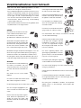
Safety Instructions and Warnings
Damaged air conditioners are not to be put into operation. In case of doubt, consult your supplier.
Use of the air conditioner is to be carried out in strict compliance with the relative instructions set forth in the User's Guide.
Installation shall be done by professional people, don't install unit by yourself.
For the purpose of safety, the air conditioner must be properly grounded in accordance with specifications.
Always remember to unplug the air conditioner before opening inlet grill. Never unplug your air conditioner by pulling on the
power cord. Always grip plug firmly and pull straight out from the outlet.
All electrical repairs must be carried out by qualified electricians. Inadequate repairs may result in a major source of danger for
the user of the air conditoiner.
Do not damage any parts of the air conditioner that carry refrigerant by piercing or perforating the air conditioner's tubes with
sharp or pointed items, crushing or twisting any tubes, or scraping the coatings off the surfaces. If the refrigerant spurts out and
gets into eyes, it may result in serious eye injuries.
Do not obstruct or cover the ventilation grille of the air conditioner. Do not put fingers or any other things into the inlet/outlet and
swing louver.
Do not allow children to play with the air conditioner. In no case should children be allowed to sit on the outdoor unit.
This appliance is not intended for use by persons (including children) with reducedphysical, sensory or mental capabilities, or
lack of experience and knowledge, unless they have been given supervision or instruction concerning use of the appliance by
a person responsible for their safety.
Children should be supervised to ensure that they do not play with the appliance.
Before starting the air conditioner, read the information given in the User's Guide carefully. The User's Guide contains very
important observations relating to the assembly, operation and maintenance of the air conditioner.
The manufacturer does not accept responsibility for any damages that may arise due to non-observation of the following
instruction.

4
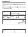
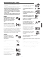
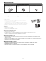
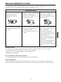
Safety Precautions
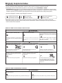
Before starting to use the system, read carefully this "SAFETY PRECAUTIONS" to ensure a proper operation of the system.
Safety precautions described here are classified to " WARNING" and " CAUTION". Precautions which are shown
in the column of " WANING" means that an improper handing could lead to a grave result like a death, serious injury,
etc. However, even if precautions are shown in the column of " CAUTION", a very serious problem could occur depending
on situation. Make sure to observe these safety precautions faithfully because they are very important information to ensure
the safety.
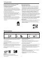
Symbols which appear frequently in the text have following meanings.
Strictly prohibited.
Observe instructions faithfully.
Provide a positive grounding.
When you have read through the manual, keep it always at hand for read consultation. If the operator is replaced, make
sure to hand over this manual to the new operator.
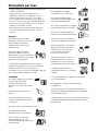
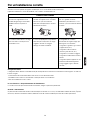
CAUTIONS FOR INSTALLATION
ON
OFF
WARNING
CAUTION
The system should be applied to places as office,
restaurant, residence and the like.
The system should be installed by your dealer or
a professional installer.
When you need some optional devices such as a
humidifier, electric heater, etc., be sure to use the products
which are recommended by us. These devices should
be attached by a professional installer.
Application to inferior environment such as an
engineering shop, could cause equipment
malfunction and serious injury or death.
Installation by yourself is not encouraged because
it could cause such problems as water leakage,
electrical shock or fire accident by some improper
handing.
Installation by yourself is not encouraged because it could
cause such problems as water leakage, electrical shock
or fire accident by some improper handing.
Do not install nearby the place where may have
leakage of flammable gas.
Depending on the place of installation, a circuit
breaker may be necessary.
Drain pipe should be arranged to provide a positive
draining.
If the gas leakes and gathers around, it may cause
the fire.
Unless the circuit breaker is installed, it could cause
elecrical shocks.
Where strong winds may prevail, the system
should be fixed securely to prevent a collapse.
Install on the place where can endure the weight
of air conditioner.
Make sure the system is grounded.
If the pipe is arranged improperly, furniture or the
likes may be damaged by leaked water.
Bodily injury could result by a collapse. Bodily injury could result by a careless installation. Grounding cable should never be connected to
a gas pipe, city water pipe, lightning conductor
rod or grounding cable of telephone. If the
grounding cable is not set properly, it could cause
electric shocks.
WARNING
CAUTIONS FOR TRANSFER OR REPAIR
Modification of the system is strictly prohibited. When the system needs a
repair, consult your dealer.
When the air conditioner is relocated, contact your dealer or a professional
installer.
Improper practice of repair could cause water leakage, electric shock or
fire.
Improper practice of installation could cause water leakage, electric shock
or fire.

Do not wash the air conditioner with water.
Do not install the system where the air outlet
reaches directly the flora and fauna.
Make sure to use a fuse of proper electric rating.
Do not operate the system while the air outlet grill
is removed.
It is strictly prohibited to place a container of
combustible gas or liquid near the air conditioner
or to spray it directly with the gas or liquid.
Neither stand on the air conditioner nor
place something on it.
Do not use the power switch to turn on or off the
system.
Do not touch the air outlet section while the swing
louver is operating.
Do not use such equipment as a water heater, etc.
around the indoor unit or the wire controller.
ON
OFF
It could cause electric shocks. It will not be good for their health. Use of steel or copper wire in place of a fuse is
strictly prohibited because it could result in a trouble
or fire accident.
There is a risk of injury.It could cause a fire accident.There are risks of falling or injury by collapsed
object.
It could cause a fire or water leakage. There is a risk of injury. If the system is operated at the vicinity of such
equipment which generates steam, condensed
water may drip during cooling operation or it could
cause a fault current or short-circuit.
When operating the system simultaneously with
a combustion apparatus, indoor air must be
ventilated frequently.
Check occasionally the support structure of the
unit for any damage after a use of long period of
time.
Insufficient ventilation could cause an oxygen
deficiency accident.
If the structure is not repaired immediately, the
unit could topple down to cause a personal injury.
When cleaning the system, stop the operation and
turn off the power switch.
Do not put water containers on the unit such as a flower vase, etc.
Cleaning should never be done while the internal
fans are running with high speed.
If the water enters into the unit and damages the electric insulation material, it may cause electric shock.
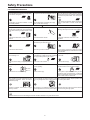
WARNING
CAUTION
CAUTIONS FOR OPERATION
You should refrain from exposing your body directly
to cool wind for a long time.
Do not poke the air inlet or outlet with a bar, etc. When any abnormal condition (scorching smell or
others) is found, stop the operation immediately
and turn off the power switch. Then consult your
dealer.
It could affect your physical condition or cause
some health problems.
Since the internal fan is operating with a high
speed, it could cause an injury.
If you continue the operation without removing the
cause, it could result in a trouble, electric shock
or fire.
The system should never be used for any other
purposes than intended such as for preservation
of food, flora and fauna, precision devices or work
of art.
Do not handle switches with a wet hand. Combustion apparatus should not be placed
allowing a direct exposure to wind of air conditioner.
Incomplete combustion could occur on the
apparatus.
It could cause electric shocks.It could cause deterioration of food or other
problems.
5
Safety Precautions

6
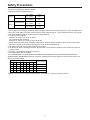
Safety Precautions
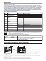
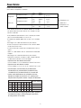
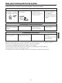
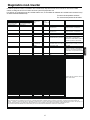
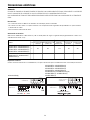
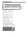
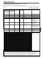
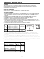
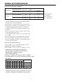
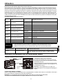
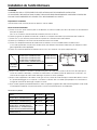
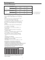
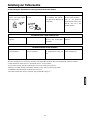
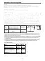
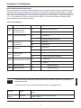
1. Applicable ambient temperature range:
The machine is adaptive in following situation
Cooling
Heating
Indoor temperature
Outdoor temperature
Indoor temperature
Outdoor temperature
max. DB/WB
min. DB/WB
max. DB/WB
min. DB/WB
max. DB/WB
min. DB/WB
max. DB/WB
min. DB/WB
32/23 C
18/14 C
46/26 C
10/6 C
27 C
15 C
24/18 C
-15 C
2. If the supply cord is damaged, it must be replaced by the manufacturer or its service agent or a similar qualified person.
3. If the fuse on the indoor PC board is broken please change it with the type of T 6.3A /250VAC(For series 24,28,36,48).
4. The wiring method should be in line with the local wiring standard.
5. The power cable should be:
H05RN-F 3G 4.0mm
2
(For series 12,18,24);
The connecting cable should be:
H05RN-F 4G 1.3mm
2
(For series 12,18,24,28,36,48)
All the cables shall have got the European authentication certificate. During installation, when the connecting cables
break off, it must be assured that the grouding wire is the last one to be broken off.
6. The power cable and connect cable should be self-provided.
7. The breaker of the air conditioner should be all-pole switch, and the distance between its two contacts should be no
less than 3mm.
8. The indoor unit installation height is at least 2.5m.
9. A leakage breaker must be installed.
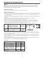
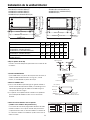
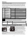
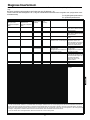
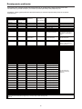
10.For AD12MS1ERA and AD12MS1ERA(D),AD18MS1ERA,AD18MS1ERA(D),AD24MS2ERA,AD24MS2ERA(D),
AD28MS2ERA(S),AD28MS2ERA(S)(D),we can get the 4 different ESP through adjust the indoor unit PCB SW1-4 and
SW1-5, please refer below:
Attention: cut off the power supply to adjust the SW1-4, and SW1-5, or else the operation is invalid.
SW1
(1) (2) (3) (4) (5) (6) (7) (8)
Static pressure
10 Pa
30 Pa
50 Pa
70 Pa
OFFOFF
OFFON
ON OFF
ON ON
- - - - - -
- - - - - -
- - - - - -
- - - - - -

Attention:
Unit model with the letter D is the mechine without water pump.
Unit model without the letter D is the mechine with water pump.
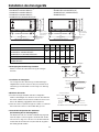
AD12MS1ERA AD12MS1ERA(D)
AD24MS1ERA
AD28NS1ERA(S) AD36NS1ERA(S) AD48NS1ERA(S)
AD24MS1ERA(D)
7
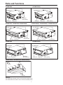
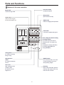
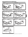
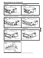
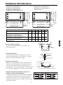
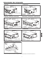
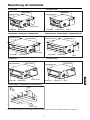
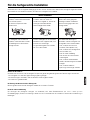
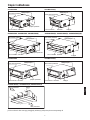
Parts and Functions
Electrical components Case
Drain pan Evaporator
Air outlet frame
The pump
drain opening
Electrical components Case
Air outlet frame
Drain pan Evaporator
The pump
drain opening
Air outlet
Air inlet
Duct
The pump
drain opening
Electrical components Case
Drain pan
Evaporator
Air outlet frame
Electrical components Case
Drain pan Evaporator
Air outlet frame
Drain opening
Electrical components Case
Air outlet frame
Drain pan Evaporator
Drain opening
Drain opening
Electrical components Case
Drain pan Evaporator
Air outlet frame
AD18MS1ERA AD24MS2ERA AD28MS2ERA(S) AD18MS1ERA(D) AD24MS2ERA(D) AD28MS2ERA(S)(D)

8
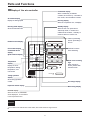
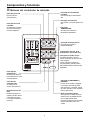
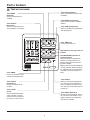
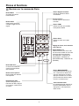
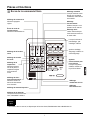
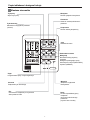
Parts and Functions
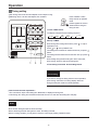
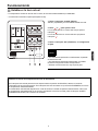
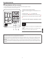
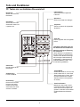
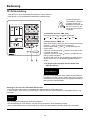
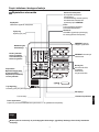
Buttons of the wire controller
Reset key
When in abnormal state, push the
reset key with a spike, which may
return the unit to normal
Health switch
Used to control oxygen
function and negative ion
Filter reset
After cleaning air inlet
and filter, press
this switch. The unit
begins to run
ON/OFF switch
Do on and off function. The unit is
on when pressing it; and is off
when pressing it again.
Fan speed switch
Change wind speed
Time switch
It is used to regulate setting time.
Self-inspection
switch
It is used for inspection
service
Air change switch
It is used to open and close air
change function. The mode is as
follows:
No display-air change (automatic)-
air change (RECOVERY)-air
change (NORMAL)
Clock, timing and address setting
Timing switch
It is used for choosing
timing running
Mode switch
Choose running mode
Swing switch
Open and close air flap
TEMP switch
Used for changing set temperature
AUTO
FAN ONLY
COOL
DRY
HEAT
TES
FAN
AUTO
HIGH
LOW
FIX
CENTRAL
OPERATION
STANDBY
PRE-HEAT
DEFROST
FILTER
MODE
HEALTH
SWING
CHECK
UNIT NO.
C
F
DEMAND
CEN. ADD.
SYS. ADD.
MANUAL
ROOM TEMP.
SET TEMP.
TIMER
VENTILATION
CLOCK UP DOWN
ON
OFF
DAILY
AUTO
RECOVERY
NORMAL
MODE FAN SWING
HEALTH
CLOCK
TIMER
CHECK FILTER
RESET
ON/OFF
SET RECOVERY
TEMP
TIME
MED

9
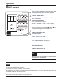
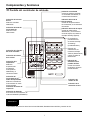
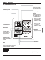
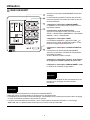
Parts and Functions
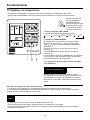
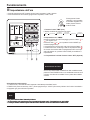
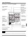
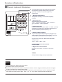
Standby display
When the unit is on power and in
"abnormity mode", or outdoor unit
malfunction show alarm , "standby" is
shown to reflect no need to unit.
Display of the wire controller
Remarks
The models in the manual don't have health, filter reset and Air change function.
Running mode display
Show the selected mode
Wind swing display
Filter screen warning
sign
When the sign is
shown, please clean
the filter screen
Centralized display
When controlled by centralized
controller, and chosen by "centralize or
lock" mode, this information is shown.
Timing operation
display
Show timing operation
content
Temperature
display
Display the room
temperature, setting
temperature, and
unit number
Air volume display
Display the setting speed
Inspection status display
Air change display
Health function display
Unit number display
Centralized adress
display
System adress display
Running display
When the compressor runs, it displays.
Demand display
When forced to run,"DEMAND"
will be displayed , or show HH/LL
in the temperature zone.
"Defrost" is shown
when defrosting.
When in preheating
status, "preheating" is
shown.
AUTO
FAN ONLY
COOL
DRY
HEAT
TES
FAN
AUTO
HIGH
LOW
FIX
CENTRAL
OPERATION
STANDBY
PRE-HEAT
DEFROST
FILTER
MODE
HEALTH
SWING
CHECK
UNIT NO.
C
F
DEMAND
CEN. ADD.
SYS. ADD.
MANUAL
ROOM TEMP.
SET TEMP.
TIMER
VENTILATION
CLOCK UP DOWN
ON
OFF
DAILY
AUTO
RECOVERY
NORMAL
MODE FAN SWING
HEALTH
CLOCK
TIMER
CHECK FILTER
RESET
ON/OFF
SET RECOVERY
TEMP
TIME
MED

10
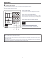
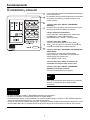
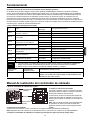
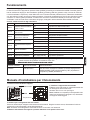
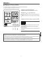
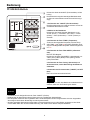
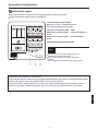
Operation
ON/OFF operation
Press ON/OFF switch on line controller directly
The line controller displays the running state in the latest
time (timing and swing state may not be displayed).
1. Press "ON/OFF" switch.
The air conditioner starts operating, and the light on the
wired controller is on.
3.Press "TEMP" switch
Change set temperature:press TEMP or TEMP every
time, [SET] will display,and set temperature will
increase/reduce
4.Press "FAN SPEED" switch
FAN ONLY Operation:
Press "FAN SPEED" switch to change to
"HIGH"--"MED"--"LOW"--"HIGH"
In AUTO,COOL,DRY,HEAT Operation:
Press "FAN SPEED" switch to change to
"AUTO"--"HIGH"--"MED"--"LOW"--"AUTO"
Avoid pressing "ON/OFF" switch frequently.
Do not press line controller or switches by sharp objects.
The temperature is on the basis of the setting value. The wind temperature may not reach the setting value because of
the outer air conditioner and system protection.
When the wired controller is power on, the screen fully displays it for two seconds. and clock zone "8888"-"888"-"88"-"8"
flicker for 30 seconds. All the switches are invalid at the time.
Remarks
Note
5.Press "swing" switch on the line controller to
swing the wind screen.
6.Press "ON/OFF"switch, off.
The light on the line controller is off.
2.Choose operation mode.
Press "mode"switch to change to
"AUTO"---"FAN ONLY"---"COOL"---"DRY"---"HEAT".
HIGH
C
ROOM TEMP.
COOL
FAN
OPERATION
MODE
CLOCK
MODE FAN SWING
HEALTH
CLOCK
TIMER
CHECK FILTER
RESET
ON/OFF
SET RECOVERY
TEMP
TIME
2
4
5
3
1
6
Several seconds after the operation of the line controller,
the setting of the unit will change.

11
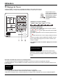
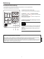
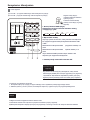
Operation
1.Press "CLOCK" switch
2.Press " " and " " to regulate the time.
Setting of power failure compensation function
When SW1-6 on PCB of wire controller is OFF, it will be in power failure compensation. If the SW1-6 is ON, it has no
compensation function.
When the power is on after blackout, the unit will return to the former state if compensation function is set. Otherwise, it
will stop. When restarting the unit, press "ON/OFF" switch on wired controller.
3.Press "setting" switch. The setting is achieved.
"CLOCK" flickers, and the time displayed is the real time.
The time increases a minute each time you press " " switch.
The time decreases a minute each time you press " " switch.
If not in timing, the screen displays the real time.
If in timing, the screen displays the timing time.
If you want to know the real time, go to the first step.
Notes
The timing is based on the real time. Thus, the real time should be regulated in advance.
The clock regulation steps are as follows:
123
HIGH
C
ROOM TEMP.
HEAT
FAN
OPERATION
MODE
CLOCK UP
MODE FAN SWING
HEALTH
CLOCK
TIMER
CHECK FILTER
RESET
ON/OFF
SET RECOVERY
TEMP
TIME
Present time setting

12
Operation
2.Set up "TIMER"
The display changes with the following sequence:
on
OFF
OFF
CYCLE
ON
no display
1.Press "TIME" switch.
The shorter setting time will be carried out firstly.
If the ON timing and OFF timing are the same, the setting is invalid.
Even in timing condition, you may start or close the unit through pressing "ON/OFF" switch.
Notes
Timing setting
Press "ON/OFF" switch
firstly, and set up operation
mode.
Please regulate the clock in
advance before using the
timing function.
3.Time setting is achieved. Press"setting"switch.
If you want to change the timing mode to normal operation,
press "timing" until there is no timing display. When the
timing is invalid, the mode is in normal operation.
Cancel timing
1.The unit starts or stops at the setting time. Meanwhile, it displays the timing time.
2."ON Timing, OFF timing and circulation"means that the unit is on and off at the setting time everyday.
When timing ON or timing OFF flickers, press " " or " " to
regulate the time
Press" "or " "set up ON/OFF time.
The setting time increases ten minutes each time you press " "
switch.
The setting time decreases ten minutes each time you press " "
switch.
When setting timing ON and timing OFF at the same time,
press "timing" switch to change the setting item.
on
OFF
HIGH
C
ROOM TEMP.
123
COOL
FAN
OPERATION
MODE
TIMER
ON
MODE FAN SWING
HEALTH
CLOCK
TIMER
CHECK FILTER
RESET
ON/OFF
SET RECOVERY
TEMP
TIME
OFF timing: when a set time has elapsed, the unit stops running.
ON timing: when a set time has elapsed, the unit starts.
parts of wired controller explanation :

1. Switches or jumper wire must be adjusted when the wire controller is powered off. If the wire controller is
powered on, the above operations will be invalid.
2. Function difference between master wire controller and slave one:
Notes
Factory Setting OFF default settingSW1-8
Installation Manual For Wire Controller
Factory Seting ON default settingSW1-7
13
Operation
Query indoor malfunction history:
In the state of power on or power off, press [CHECK] button, enter the malfunction-querying mode of all indoor units in
the group. Then [CHECK] and [UNIT NO.] will display, and the actual indoor numbers will be displayed in some sequence
(unit number is in decimals). At the same time, in the time region, there will be the current malfunction and the latest time
malfunction, the displaying format is [XX:YY], in which XX stands for the current malfunction, if normal, it will display "--";
YY stands for the latest time malfunction. The failure code of every unit will display for 3 seconds. After the failure codes
of all indoor units in the whole group are displayed, the mode will quit automatically.
How to change the function switches?
Master wire
controller
Slave wire controller
Function All of functions
Only with below functions: ON/OFF, MODE, FAN
SPEED, SET TEMP., SWING
Contrastive
items
No. Type State of switch Function description
Select the master or
the slave controller
ON set as the slave controller
OFF
SW1-1
OFF set as the master controller
Select the controller
mode
ON
standard controller
SW1-2
air handler controller
Room temperature
display option
ON
visible room temperature
SW1-3
invisible room temperature
26
o
lock
ON
Unavailable 26
o
lock
SW1-4
available 26
o
lock
Temperature sensor
position option
ON
Sensor of the controller
SW1-5
Sensor in the unit
OFF
Auto restart
ON unavailable
SW1-6
available
OFF
OFF
OFF
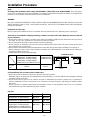
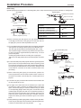
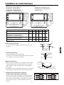
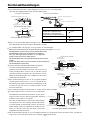
3.Wiring instruction
Use shielded wire between indoor and wire controller.And be earthed on one side, or the unit will not work normally
because of interference.
Note:Confirm the terminal connection firmly, and do not get in tough with shielded wire.
4.Place wire controller on the holder, and pay attention not to pressing any wires.
10.45
Screw holes
5.3
Bracket
Wire controller
1. Take down wire controller from the holder
2. Install the controller holder
According to the position of 2 screw holes on the
holder, drill 2 holes on the wall, and strike the wood
stopper to the holes respectively.
Then align the 2 screw holes of wired controller
holder to the wood stopper, fix the holder on the wall
with wood screw.
Note:Try a wall as flat as possible for installation.
Don't use excessive force to tighten screws,
otherwise, the holder will be damaged.
AUTO
FAN ONLY
COOL
DRY
HEAT
TES
FAN
AUTO
HIGH
LOW
FIX
CENTRAL
OPERATION
STANDBY
PRE-HEAT
DEFROST
FILTER
MODE
HEALTH
SWING
CHECK
UNIT NO.
C
F
DEMAND
CEN. ADD.
SYS. ADD.
MANUAL
ROOM TEMP.
SET TEMP.
TIMER
VENTILATION
CLOCK UP DOWN
ON
OFF
DAILY
AUTO
RECOVERY
NORMAL
MODE FAN SWING
HEALTH
CLOCK
TIMER
CHECK FILTER
RESET
ON/OFF
SET RECOVERY
TEMP
TIME
MED

Installation Manual For Wire Controller
14
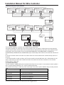
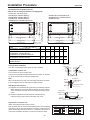
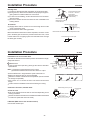
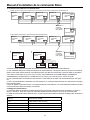
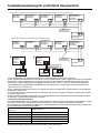
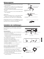
5. Wiring connections of wire controller:
Indoor 1
Wire controller
A B C
Wire controller
Polar wire
Indoor 1
Wire controller
A B C
Wire controller
Polar wire
A B C
Wire controller
Polar wire
BC
A B C A B C
ABCABCAB
ABC
CABCABC
Indoor 1 Indoor 2 Indoor N Indoor 15 Indoor 16
Wire controller
Control wiring
of wire
controller
TYPE 2, FOR AD24MS1ERA, AD24MS1ERA(D),AD28/36/48NS1ERA(S)
ABCABC
AB
ABC
C
ABC
ABC
A
Indoor 1
Wire controller
port
Indoor 2 Indoor N Indoor 15 Indoor 16
Wire controller
Control wiring
of wire
controller
Wire controller
port
Wire controller
port
Wire controller
port
Wire controller
port
(master unit)
Wire controller
port
Wire controller
port
Wire controller
port
Wire controller
port
Wire controller
port
(master unit)
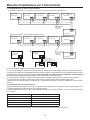
TYPE 1, FOR AD12/18MS1ERA,AD12/18MS1ERA(D),AD24MS2ERA,AD24MS2ERA(D),AD28MS2ERA(S),AD28MS2ERA(S)(D)
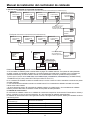
There are three methods to connection wire controller and the indoor units:
A.One wired controller can control max. up to 16 sets of indoor units, and 3 pieces of polar wire must connect the wire
controller and the master unit (the indoor unit connected with wire controller directly), the others connect with the master
unit through 2 pieces of polar wire( 3 pieces for model AD12/18MS1ERA, AD12/18MS1ERA(D),AD24MS2ERA,
AD24MS2ERA(D) and the bridge CN22 CN23 on slave units PCB should be cut
off ).
B. One wire controller controls one indoor unit, and the indoor unit connects with the wire controller through 3 pieces of
polar wire.
C. Two wired controllers control one indoor unit. The wire controller connected with indoor unit is called master one, the
other is called slave one. Master wire controller and indoor unit; master and slave wire controllers are all connected
through 3 pieces of polar wire.
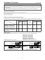
6. Communication wiring:
The wire controller is equipped with special communication wiring in the accessories. 3-core terminal (1-white 2-yellow 3-
red) is connected with the terminal A, B, C of wire controller respectively.
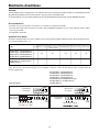
The communication wiring is 5 meter long; if the actual length is more than it, please distribute wiring according to below
table:
Communication wiring length(m) Dimensions of wiring
< 100 0.3mm
2
x3-core shielded wire
100 and <200 0.5mm
2
x3-core shielded wire
200 and <300 0.75mm
2
x3-core shielded wire
300 and <400 1.25mm
2
x3-core shielded wire
400 and <600 2mm
2
x3-core shielded wire
*One side of the shielded sheet of communication wire must be earthed.
, AD28MS2ERA(S), AD28MS2ERA(S)(D)

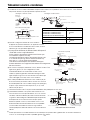
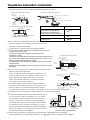
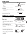
"HOT KEEP" function
Heating Mode
15
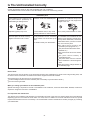
"HOT KEEP" is operated in the following cases.
When heating is started:
In order to prevent blowing out of cool wind, the indoor unit fan stopped according to the room temperature which heating
operation is started. Wait for approx. 2 to 3 minute, and the operation will be automatically changed to the ordinary heating
mode.
Defrosting operation (in the heating mode):
When it is liable to frost, the heating operation is stopped automatically for 5 to 12 minutes once per approx. one hour,
and defrosting is operated. After defrosting is completed, operation mode is automatically changed to ordinary heating
operation.
When the room thermostat is actuated:
When room temperature increases and room temperature controller actuates, the fan speed is automatically changed to
stop under low temperature condition of indoor heat exchanger. When room temperature decreases, air conditioner
automatically changes over to ordinary heating operation.
Heat pump type warming
With the heat pump type warming, the mechanism of heat pump that concentrate heat of outdoor air with the help of
refrigerant to warm the indoor space, is utilized.
Defrosting operation
When a room is warmed with a heat pump type air conditioner, frost accumulates on the heat exchanger of outdoor unit
along with the drop of indoor temperature. Since the accumulated frost reduces the effect of warming, it is necessery to
automatically switch the operation to the defrosting mode. During the defrosting operation, heating operation is interrupted.
Atmospheric temperature and warming capacity
Warming capacity of heat pump type air conditioner decreases along with the drop of outdoor temperature.
When the warming capacity is not sufficient, it is recommended to use another heating implement.
Period of warm-up
Since the heat pump type air conditioner employs a method to circulate warm winds to warm
the entire space of a room, it takes time before the room temperature rises.
It is recommendable to start the operation a little earlier in a very cold morning.
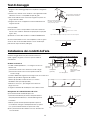
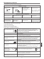
Warming operation

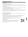
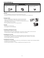
Points to observe
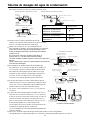
Turn off the power supply switch. Do not touch with wet hand. Do not use hot water or volatile liquid.
ON
OFF
Thinner
Do not
use!
Benzine
Tooth powder
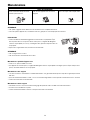
Cleaning the air filter
Do not dry the air filter with fire.
Do not run the air conditioner without the air filter.
Pre-Season Care
See that there are no obstacles blocking the air inlet and air outlet of both indoor and outdoor units.
Make sure that the air filter is not dirty.
Cut in the power supply switch 12 hours before starting run.
Post-Season Care
Operate the unit with FAN mode on a fair day for about half a day to dry the inside of the unit well.
Stop operation and turn off the power supply switch. Electric power is consumed even the air conditioner is in stop.
Clean the air filter and set it in the place.
Care and Cleaning of the unit
Clean with soft and dry cloth.
If it is very dirty, dissolve neutral detergent in the lukewarm water and make the cloth wet with the water. After wiping,
clean off the detergent using clean water.
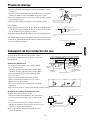
1.Clean the air filter by lightly tapping it or with the cleaner. It is more effective to clean
the air filter with water.
If the air filter is very dirty, dissolve neutral detergent in the lukewarm water (approx. 30 C),
rinse the air filter in the water, and thoroughly wash the air filter off the detergent
in the plain water.
2.After drying the air filter, set it up on the air conditioner.
Do not open the inlet grill until fan stops completely.
Fan will continue rotating for a while by the law of inertia after operation is being stopped.
CAUTION
CAUTION
Care and Maintenance
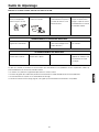
16

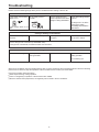
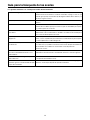
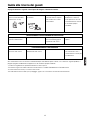
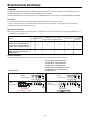
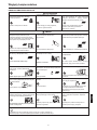
Please check the following things about your air conditioner before making a service call.
When the air conditioner does not operate properly after you have checked the above mentioned items or when the following
phenomenon is observed, stop the operation of the air conditioner and contact your sales dealer.
The fuse or breaker often shuts down.
Water drops off during cooling operation.
There is a irregularity in operation or abnormal sound is audible.
When the CHECK LED (red) flickers, an irregularity has occurred in the air conditioner.
Unit fails to start
ON
OFF
Is the power source switch
adjust cut in?
Is city supply power in
normal?
Isn't the signal receiving
section exposed to the direct
sunlight or strong illumination?
Isn't the earth leakage breaker
in action?
It is dangerous. Turn off the
power supply switch
immediately and contact the
sales dealer.
Power supply switch is not
ON.
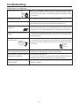
Cooling or heating is not sufficient
Is the thermostat adjust as
required?
Isn't the air filter dirty? Isn't any doors or windows
left open?
Doesn't any obstacle exist at
the air inlet or outlet?
Cooling is not sufficient
Isn't sun-shine invading direct? Isn't any unexpected heating
load generated?
Isn't the room much crowded?
Isn't the swing louver horizontal? (At HEATING mode)
If swing louver is horizontal, the blow wind does not reach floor.
The wind does not blow during
heating operation
Isn't it warming up?
Power
stoppage?
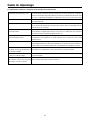
Troubleshooting
17

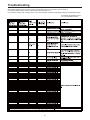
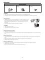
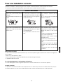
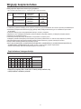
The followings are not malfunction
Shuru
Shuru
When the air conditioner is started, when the compressor starts or stops
during operation or when the air conditioner is stopped, it sometimes sounds
"shuru shuru" or "gobo gobo". It is the flowing sound of the refrigerant, and it
is not a trouble.
Water flowing sound is heard.
This is caused by heat expansion or contraction of plastics.Cracking sound is heard.
It smells. Air which blows out from the indoor unit sometimes smells. The smell results
from residents of tobacco smoke or cosmetics stuck inside of unit.
When the air conditioner is used at restaurant etc. where dense edible oil
fume is always exists, white fog sometimes blows out of air outlet during
operation. In this case consult sales dealer for cleaning the heat exchanger.
During operation, white fog comes out
of indoor unit.
Unit does
not start
Wait for
three
minutes
It is switched into the FAN mode during
cooling.
To prevent frost from being accumulated on the indoor unit heat exchanger,
it is sometimes automatically switched to the FAN mode,but it will soon return
to the cooling mode.
Even if the operation switch is turned on, cooling, dehumidifying or heating
is not operable for three minutes after the conditioner is stopped. Because
the protecting circuit is activated. (During this time air conditioner operates
in fan mode.)
The air conditioner can not be restarted
soon after it stops.
Air does not blow or the fan speed can
not be changed during dehumidifying.
During operation, operation mode has
changed over automatically.
Water or steam generates from the outdoor
unit during heating.
When it is excessively cooled during dehumidifying, the blower
automatically repeats reducing and lowering the fan speed.
Isn't the AUTO mode selected?
In the case of AUTO mode, operation mode is changed automatically from
cooling to heating or vise-versa according to the room temperature.
This results when frost accumulated on the outdoor unit is removed (during
defrosting operation).
Troubleshooting
18
La page est en cours de chargement...
La page est en cours de chargement...
La page est en cours de chargement...
La page est en cours de chargement...
La page est en cours de chargement...
La page est en cours de chargement...
La page est en cours de chargement...
La page est en cours de chargement...
La page est en cours de chargement...
La page est en cours de chargement...
La page est en cours de chargement...
La page est en cours de chargement...
La page est en cours de chargement...
La page est en cours de chargement...
La page est en cours de chargement...
La page est en cours de chargement...
La page est en cours de chargement...
La page est en cours de chargement...
La page est en cours de chargement...
La page est en cours de chargement...
La page est en cours de chargement...
La page est en cours de chargement...
La page est en cours de chargement...
La page est en cours de chargement...
La page est en cours de chargement...
La page est en cours de chargement...
La page est en cours de chargement...
La page est en cours de chargement...
La page est en cours de chargement...
La page est en cours de chargement...
La page est en cours de chargement...
La page est en cours de chargement...
La page est en cours de chargement...
La page est en cours de chargement...
La page est en cours de chargement...
La page est en cours de chargement...
La page est en cours de chargement...
La page est en cours de chargement...
La page est en cours de chargement...
La page est en cours de chargement...
La page est en cours de chargement...
La page est en cours de chargement...
La page est en cours de chargement...
La page est en cours de chargement...
La page est en cours de chargement...
La page est en cours de chargement...
La page est en cours de chargement...
La page est en cours de chargement...
La page est en cours de chargement...
La page est en cours de chargement...
La page est en cours de chargement...
La page est en cours de chargement...
La page est en cours de chargement...
La page est en cours de chargement...
La page est en cours de chargement...
La page est en cours de chargement...
La page est en cours de chargement...
La page est en cours de chargement...
La page est en cours de chargement...
La page est en cours de chargement...
La page est en cours de chargement...
La page est en cours de chargement...
La page est en cours de chargement...
La page est en cours de chargement...
La page est en cours de chargement...
La page est en cours de chargement...
La page est en cours de chargement...
La page est en cours de chargement...
La page est en cours de chargement...
La page est en cours de chargement...
La page est en cours de chargement...
La page est en cours de chargement...
La page est en cours de chargement...
La page est en cours de chargement...
La page est en cours de chargement...
La page est en cours de chargement...
La page est en cours de chargement...
La page est en cours de chargement...
La page est en cours de chargement...
La page est en cours de chargement...
La page est en cours de chargement...
La page est en cours de chargement...
La page est en cours de chargement...
La page est en cours de chargement...
La page est en cours de chargement...
La page est en cours de chargement...
La page est en cours de chargement...
La page est en cours de chargement...
La page est en cours de chargement...
La page est en cours de chargement...
La page est en cours de chargement...
La page est en cours de chargement...
La page est en cours de chargement...
La page est en cours de chargement...
La page est en cours de chargement...
La page est en cours de chargement...
La page est en cours de chargement...
La page est en cours de chargement...
La page est en cours de chargement...
La page est en cours de chargement...
La page est en cours de chargement...
La page est en cours de chargement...
La page est en cours de chargement...
La page est en cours de chargement...
La page est en cours de chargement...
La page est en cours de chargement...
La page est en cours de chargement...
La page est en cours de chargement...
La page est en cours de chargement...
La page est en cours de chargement...
La page est en cours de chargement...
La page est en cours de chargement...
La page est en cours de chargement...
La page est en cours de chargement...
La page est en cours de chargement...
La page est en cours de chargement...
La page est en cours de chargement...
La page est en cours de chargement...
La page est en cours de chargement...
La page est en cours de chargement...
La page est en cours de chargement...
La page est en cours de chargement...
La page est en cours de chargement...
La page est en cours de chargement...
La page est en cours de chargement...
La page est en cours de chargement...
La page est en cours de chargement...
La page est en cours de chargement...
La page est en cours de chargement...
La page est en cours de chargement...
La page est en cours de chargement...
La page est en cours de chargement...
-
 1
1
-
 2
2
-
 3
3
-
 4
4
-
 5
5
-
 6
6
-
 7
7
-
 8
8
-
 9
9
-
 10
10
-
 11
11
-
 12
12
-
 13
13
-
 14
14
-
 15
15
-
 16
16
-
 17
17
-
 18
18
-
 19
19
-
 20
20
-
 21
21
-
 22
22
-
 23
23
-
 24
24
-
 25
25
-
 26
26
-
 27
27
-
 28
28
-
 29
29
-
 30
30
-
 31
31
-
 32
32
-
 33
33
-
 34
34
-
 35
35
-
 36
36
-
 37
37
-
 38
38
-
 39
39
-
 40
40
-
 41
41
-
 42
42
-
 43
43
-
 44
44
-
 45
45
-
 46
46
-
 47
47
-
 48
48
-
 49
49
-
 50
50
-
 51
51
-
 52
52
-
 53
53
-
 54
54
-
 55
55
-
 56
56
-
 57
57
-
 58
58
-
 59
59
-
 60
60
-
 61
61
-
 62
62
-
 63
63
-
 64
64
-
 65
65
-
 66
66
-
 67
67
-
 68
68
-
 69
69
-
 70
70
-
 71
71
-
 72
72
-
 73
73
-
 74
74
-
 75
75
-
 76
76
-
 77
77
-
 78
78
-
 79
79
-
 80
80
-
 81
81
-
 82
82
-
 83
83
-
 84
84
-
 85
85
-
 86
86
-
 87
87
-
 88
88
-
 89
89
-
 90
90
-
 91
91
-
 92
92
-
 93
93
-
 94
94
-
 95
95
-
 96
96
-
 97
97
-
 98
98
-
 99
99
-
 100
100
-
 101
101
-
 102
102
-
 103
103
-
 104
104
-
 105
105
-
 106
106
-
 107
107
-
 108
108
-
 109
109
-
 110
110
-
 111
111
-
 112
112
-
 113
113
-
 114
114
-
 115
115
-
 116
116
-
 117
117
-
 118
118
-
 119
119
-
 120
120
-
 121
121
-
 122
122
-
 123
123
-
 124
124
-
 125
125
-
 126
126
-
 127
127
-
 128
128
-
 129
129
-
 130
130
-
 131
131
-
 132
132
-
 133
133
-
 134
134
-
 135
135
-
 136
136
-
 137
137
-
 138
138
-
 139
139
-
 140
140
-
 141
141
-
 142
142
-
 143
143
-
 144
144
-
 145
145
-
 146
146
-
 147
147
-
 148
148
-
 149
149
-
 150
150
-
 151
151
-
 152
152


Haier AD12MS1ERAD Operating Manual And Instructions
- Catégorie
- Climatiseurs split-system
- Taper
- Operating Manual And Instructions
dans d''autres langues
- italiano: Haier AD12MS1ERAD
- English: Haier AD12MS1ERAD
- español: Haier AD12MS1ERAD
- Deutsch: Haier AD12MS1ERAD
- polski: Haier AD12MS1ERAD
Documents connexes
-
Haier 2HUM18R03/R2(DB) Mode d'emploi
-
Haier AP48DS1ERA Operation Manual And Installation Manual
-
-
-
-
-
-
Haier QACT17A Manuel utilisateur
-
Autres documents
-
mundoclima Series MUPO-H8 Guide d'installation
-
Mitsubishi Electric PKA-A12HA7 Le manuel du propriétaire
-
Tosot TPAC12S-H116A3 Manuel utilisateur
-
 Olimpia Splendid Ci2 Wall Series Manuel utilisateur
-
Airwell SBF Le manuel du propriétaire
-
 Terma zdalnego programatora DT-IR Mode d'emploi
-
HTW V10 VRF UNIDAD EXTERIOR Manuel utilisateur
-
Thermex Silent 300 CZ Scandic Guide d'installation
-
-
Samsung MRW-TS Manuel utilisateur

