CAMPAGNOLA 0310.0123 forbice S. STAR Doppio taglio Le manuel du propriétaire
- Catégorie
- Outils électroportatifs
- Taper
- Le manuel du propriétaire

CAMPAGNOLA S.r.l.
Via Lazio, 21-23 • 40069 Zola Predosa - Bologna - Italy
Tel. +39/051753500 - Fax +39/051752551
Internet: www.campagnola.it - e-mail: [email protected]
CAMPAGNOLA IBÉRICA DE SUMINISTROS AGRÌCOLAS SL.
Tel. +34/938 444 185 fax +34/938 444 184
e-mail: [email protected]
Mod. SUPER STAR SF
Mod. SUPER STAR SV
Mod. SUPER STAR SDT
Remarques
pour entretien
périodiques
Notas para
mantenimientos
periódicos
Hinweise für die
periodische
Wartung
Notes for
scheduled
maintenance
Note per
manutenzioni
periodiche
MANUALE USO E MANUTENZIONE FORBICE PNEUMATICA
PNEUMATIC PRUNING SHEARS USE AND MAINTENANCE MANUAL
GEBRAUCHS-UND WARTUNGSANWEISUNG FÜR DIE PNEUMATISCHE SCHERE
LIVRET D’UTILISATION ET D’ENTRETIEN DU SECATEUR A AIR COMPRIME
MANUAL DE UTILIZACION Y MANTENIMIENTO DE LA TIJERA NEUMATICA
6
7
Zola Predosa, 12/07/2011
2006/42/CE
UNI EN ISO 12100-1 - UNI EN ISO 12100-2 - UNI EN ISO 13857
UNI EN ISO 13732-1 - UNI EN ISO 3767-5 - UNI EN 1037
UNI EN 983 - ISO 11684
Tipo: Forbice pneumatica. Funzione: potatura.
Type: Pneumatic shear. Function: pruning.
Typ: Luftdruckschere. Funktion: Beschneiden.
Type: Sécateur pneumatique. Fonction: élagage.
Tipo: Tijera neumática. Función: poda.
Τύπος: Πνευματικό ελαιοραβδιστικό. Λειτουργία: κλάδεμα.
Tip İşlev: budama.
dichiara sotto la propria responsabilità che
la macchina a lato indicata é conforme alla
Direttiva Macchine 2006/42/CE e alle seguenti
direttive e normative applicate:
states that the machine indicated here fully
complies with the 2006/42/EC Directive regard-
ing machinery and with the following directives
and standards:
erklärt auf eigene Verantwortung, dass die hier an
der Seite angegebene Maschine der Maschinen-
richtlinie 2006/42/EG und den folgenden Rich-
tlinien und angewandten Normen entspricht:
déclare sous sa propre responsabilité qui la
machine indiquée ci-contre est conforme à la
Directive Machines 2006/42/CE, aux directives
suivantes et normes applicables :
declara bajo su propia responsabilidad que la
máquina indicada aquí al lado es conforme con
la Dirección Máquinas 2006/42/CE y con las
siguientes reglas y normativas aplicadas:
δηλώνει υπεύθυνα ότι το παραπλεύρως μηχάνημα
είναι σύμφωνα με την Οδηγία Μηχανημάτων
2006/42/CE και τις παρακάτω εφαρμοσμένες
οδηγίες και νομοθεσίες:
-
Authorized person to create the technical
document.
-
Personne autorisée à constituer le fascicule
technique.
Άτομο εξουσιοδοτημένο για τη σύνταξη του τεχνικού
φακέλου.
EC DECLARATION OF COMPLIANCE
DECLARATION DE CONFORMITE CE
ΔΗΛΩΣΗ CE ΣΥΜΦΩΝΙΑΣ
The undersigned rm /La societé soussignée
/ Η υπογραφόμενη Επιχείρηση /
CAMPAGNOLA S.r.l - Via Lazio, 21-23 - 40069 ZOLA PREDOSA (BOLOGNA)
REGULATIONS APPLIED
RÉGLEMENTATIONS APPLIQUÉES
/ ΝΟΜΟΘΕΣΙΕΣ ΕΦΑΡΜΟΣΜΕΝΕΣ
EC DIRECTIVES APPLIED
DIRECTIVES CE APPLIQUÉES
ΟΔΗΓΙΕΣ CE ΕΦΑΡΜΟΣΜΕΝΕΣ
Signature of the Legal Representative
Signature du représentant légal
Υπογραφή του νόμιμου Εκπροσώπου
UNI EN ISO 5349/1-2 - UNI EN 614-1 - UNI EN ISO 3744

11 10 12 13 1 2 3
9 8 7 6 5 4 3
12
23
20
22
19
9
13
25
26
27
21
24
8
14
15
14
3332
45°
29 28
9
31
16
30
18
17
3
Zola Predosa, 12/07/2011
2006/42/CE
UNI EN ISO 12100-1 - UNI EN ISO 12100-2 - UNI EN ISO 13857
UNI EN ISO 13732-1 - UNI EN ISO 3767-5 - UNI EN 1037
UNI EN 983 - ISO 11684
Tipo: Forbice pneumatica. Funzione: potatura.
Type: Pneumatic shear. Function: pruning.
Typ: Luftdruckschere. Funktion: Beschneiden.
Type: Sécateur pneumatique. Fonction: élagage.
Tipo: Tijera neumática. Función: poda.
Τύπος: Πνευματικό ελαιοραβδιστικό. Λειτουργία: κλάδεμα.
Tip İşlev: budama.
dichiara sotto la propria responsabilità che
la macchina a lato indicata é conforme alla
Direttiva Macchine 2006/42/CE e alle seguenti
direttive e normative applicate:
states that the machine indicated here fully
complies with the 2006/42/EC Directive regard-
ing machinery and with the following directives
and standards:
erklärt auf eigene Verantwortung, dass die hier an
der Seite angegebene Maschine der Maschinen-
richtlinie 2006/42/EG und den folgenden Rich-
tlinien und angewandten Normen entspricht:
déclare sous sa propre responsabilité qui la
machine indiquée ci-contre est conforme à la
Directive Machines 2006/42/CE, aux directives
suivantes et normes applicables :
declara bajo su propia responsabilidad que la
máquina indicada aquí al lado es conforme con
la Dirección Máquinas 2006/42/CE y con las
siguientes reglas y normativas aplicadas:
δηλώνει υπεύθυνα ότι το παραπλεύρως μηχάνημα
είναι σύμφωνα με την Οδηγία Μηχανημάτων
2006/42/CE και τις παρακάτω εφαρμοσμένες
οδηγίες και νομοθεσίες:
-
Authorized person to create the technical
document.
-
Personne autorisée à constituer le fascicule
technique.
Άτομο εξουσιοδοτημένο για τη σύνταξη του τεχνικού
φακέλου.
EC DECLARATION OF COMPLIANCE
DECLARATION DE CONFORMITE CE
ΔΗΛΩΣΗ CE ΣΥΜΦΩΝΙΑΣ
The undersigned rm /La societé soussignée
/ Η υπογραφόμενη Επιχείρηση /
CAMPAGNOLA S.r.l - Via Lazio, 21-23 - 40069 ZOLA PREDOSA (BOLOGNA)
REGULATIONS APPLIED
RÉGLEMENTATIONS APPLIQUÉES
/ ΝΟΜΟΘΕΣΙΕΣ ΕΦΑΡΜΟΣΜΕΝΕΣ
EC DIRECTIVES APPLIED
DIRECTIVES CE APPLIQUÉES
ΟΔΗΓΙΕΣ CE ΕΦΑΡΜΟΣΜΕΝΕΣ
Signature of the Legal Representative
Signature du représentant légal
Υπογραφή του νόμιμου Εκπροσώπου
UNI EN ISO 5349/1-2 - UNI EN 614-1 - UNI EN ISO 3744

1 - 40
......................2
.....................26
...................32
...................20
..................14
.........................8

2 - 40
GENERALITÀ
• Questo manuale è da considerarsi parte integrante della fornitura della forbice.
• Questo manuale non può essere ceduto in visione a terzi senza autorizzazione scritta
della Ditta costruttrice.
• Tutti i diritti di riproduzione del presente manuale sono riservati alla Ditta costruttrice.
• La Ditta costruttrice si riserva il diritto di effettuare modifiche senza comunicarlo ai clienti
già in possesso di modelli simili.
NOTA: Come aiuto per una migliore comprensione del manuale uso e
manutenzione, aprire le pagine di copertina verso l’esterno per seguire
contemporaneamente i riferimenti del disegno e quelli del testo.
AVVERTENZE ANTINFORTUNISTICHE
Generalità
Prima di operare con l'attrezzo, leggere attentamente il seguente manuale.
La Ditta costruttice declina ogni responsabilità per danni conseguenti ad un uso per scopi
ed in modi diversi da quelli da essa previsti (Vedi paragrafo “Descrizione del prodotto”).
La Ditta costruttice declina ogni responsabilità per l’uso di ricambi non originali, le modifiche
o gli interventi sull'attrezzo fatti da persone non autorizzate.
Cautele particolari
• Controllare prima e durante le operazioni che l’uso dell'attrezzo non generi situazioni
pericolose per persone, animali o cose.
• Non utilizzare l'attrezzo quando si è in un equilibrio precario.
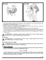
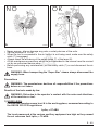
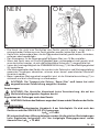
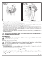
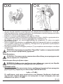
• Tenere la mano che non impugna l'attrezzo lontano da questo (vedi fig. A e B).

2 - 40
GENERALITÀ
• Questo manuale è da considerarsi parte integrante della fornitura della forbice.
• Questo manuale non può essere ceduto in visione a terzi senza autorizzazione scritta
della Ditta costruttrice.
• Tutti i diritti di riproduzione del presente manuale sono riservati alla Ditta costruttrice.
• La Ditta costruttrice si riserva il diritto di effettuare modifiche senza comunicarlo ai clienti
già in possesso di modelli simili.
NOTA: Come aiuto per una migliore comprensione del manuale uso e
manutenzione, aprire le pagine di copertina verso l’esterno per seguire
contemporaneamente i riferimenti del disegno e quelli del testo.
PROFILO AZIENDALE
La capacità di interpretare il mercato con risposte specifiche e dinamiche di insieme,
unitamente alla garanzia di una vasta conoscenza di settore, hanno fatto di CAMPAGNOLA
S.r.l. il leader mondiale per progettazione, costruzione e realizzazione di attrezzature
pneumatiche per la potatura e la raccolta.
Con il 60% di produzione destinata all’estero ed una efficace rete di vendita ed assistenza
che si avvale di personale altamente qualificato, viene offerta una vasta gamma di prodotti:
• forbici elettriche a batteria per la potatura;
• forbici pneumatiche per la potatura (anche su prolunga);
• attrezzature pneumatiche e a motore per la raccolta delle olive e del caffè e per il
diradamento della frutta;
• tosasiepi, decespugliatori e seghe a catena pneumatiche;
• compressori per applicazione ai tre punti del trattore e motocompressori carrellati;
• impianti oleari.
Le ragioni di una scelta si possono riassumere per:
• maneggevolezza e praticità dei prodotti;
• versatilità d’impiego;
• qualità dei materiali costruttivi;
• affidabilità;
• ingegneria progettuale.
AVVERTENZE ANTINFORTUNISTICHE
Generalità
Prima di operare con l'attrezzo, leggere attentamente il seguente manuale.
La Ditta costruttice declina ogni responsabilità per danni conseguenti ad un uso per scopi
ed in modi diversi da quelli da essa previsti (Vedi paragrafo “Descrizione del prodotto”).
La Ditta costruttice declina ogni responsabilità per l’uso di ricambi non originali, le modifiche
o gli interventi sull'attrezzo fatti da persone non autorizzate.
Cautele particolari
• Controllare prima e durante le operazioni che l’uso dell'attrezzo non generi situazioni
pericolose per persone, animali o cose.
• Non utilizzare l'attrezzo quando si è in un equilibrio precario.
• Tenere la mano che non impugna l'attrezzo lontano da questo (vedi fig. A e B).
3 - 40
• Non manomettere, togliere o danneggiare nessun elemento, e in particolare quelli che
garantiscono la sicurezza d’uso.
• Regolare la pressione di alimentazione al valore di 10 bar.
• Quando l'attrezzo è collegato all’aria compressa, ma non viene utilizzato, verificare
l’inserimento automatico della sicura (7).
• Controllare sempre l’efficienza della sicura (7) sulla leva di azionamento (6).
• Tutte le operazioni di manutenzione dell'attrezzo, diverse da quanto riportato nel manuale
uso e manutenzione, vanno eseguite a cura di una officina specializzata nell’assistenza.
• Prima di qualunque manutenzione inserire la sicura (7) e distaccare il tubo di
alimentazione.
ATTENZIONE: Il trasporto della forbice "Super Star" deve essere sempre
effettuato con il tubo di alimentazione distaccato.
Avvertenze
ATTENZIONE: Il costruttore declina ogni responsabilità derivante
dall'inadempienza di quanto segue.
Risultati delle prove di legge
ATTENZIONE: Rischi dovuti all’esposizione dell’operatore alla rumorosità e/
o vibrazioni della macchina o dell’attrezzo.
1) LIVELLO SONORO
Livello di pressione acustica continuo equivalente ponderato A nel posto di lavoro
misurato secondo la normativa UNI EN ISO 3744:
LpA
eq
= 87 dBA
I valori equivalenti riscontrati in corrispondenza delle diverse attrezzature
ausiliarie risultano essere di valore elevato in quanto superano il limite di soglia
di riferimento fissato LpA
eq
= 70 dBA.
270193 270194
B
A

4 - 40
Pertanto dovranno essere eseguite le seguenti disposizioni:
• L’operatore dovrà essere sottoposto a controllo sanitario periodico.
• L’operatore dovrà essere informato sui rischi dovuti all’esposizione sonora.
• Impiego obbligatorio di cuffie antirumore o altri sistemi di protezione dell’udito.
2) LIVELLO VIBRAZIONI
Il valore quadratico medio ponderato in frequenza dell’accelerazione trasmessa
al sistema mano-braccio al quale è esposto l’utilizzatore misurato secondo la
EN ISO 5349/1-2:
Forbice diretta a
heq
= 5,06 m/s
2
Forbice con asta fissa m 0,5 a
heq
= 3,95 m/s
2
Forbice con asta telescopica vetroresina m 1,85 ÷ 3,15 a
heq
= 2,80 m/s
2
Forbice con asta telescopica alluminio m 1,25 ÷ 1,95 a
heq
= 2,80 m/s
2
Forbici montate con aste telescopiche varie lunghezze a
heq
= <2,50 m/s
2
I valori equivalenti riscontrati in corrispondenza delle diverse attrezzature
ausiliarie risultano essere di valore elevato in quanto superano il limite di soglia
di riferimento fissato a 2,5 m/s
2
e pertanto dovranno essere eseguite le seguenti
disposizioni:
• L’operatore dovrà essere sottoposto a controllo sanitario periodico.
• L’operatore dovrà essere informato sui rischi dovuti all’esposizione alle vibrazioni.
• Limite max di 6 ore giornaliere lavorative e continuative.
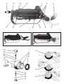
DESCRIZIONE
Descrizione del prodotto
Forbice pneumatica ad una lama tagliente destinata alla potatura di piante da frutto.
La forza di taglio viene data da un cilindro pneumatico posto dentro all’impugnatura (1)
alimentato da una linea di aria compressa e azionabile da una leva (6) aderente
all’impugnatura.
Sulla leva di azionamento (6) è posta la sicura (7), che si inserisce automaticamente al
rilascio della stessa.
Sicura manuale da inserire per prolungate pause di lavoro.
• Mod. Super Star SF indicata per alberi da frutto (una lama tagliente).
• Mod. Super Star SV indicata per i vigneti (una lama tagliente) (32).
• Mod. Super Star SDT indicata per alberi da frutta in genere (due lame taglienti ) (33).
ATTENZIONE: Se la forbice viene utilizzata per il taglio di materiali diversi da
quelli sopra elencati può danneggiare gravemente l’attrezzo e la sicurezza
della persona.
Caratteristiche
• Funzionamento pneumatico.
• Impugnatura ergonomica in resina acetalica (1).
• Leva di azionamento ergonomica (6).
• Protezione dita (5).
• Lame in acciaio temperato (3).
• Sicura manuale (9).
• Sicura automatica (7).
• Possibilità di montaggio su prolunga (28).

4 - 40
Pertanto dovranno essere eseguite le seguenti disposizioni:
• L’operatore dovrà essere sottoposto a controllo sanitario periodico.
• L’operatore dovrà essere informato sui rischi dovuti all’esposizione sonora.
• Impiego obbligatorio di cuffie antirumore o altri sistemi di protezione dell’udito.
2) LIVELLO VIBRAZIONI
Il valore quadratico medio ponderato in frequenza dell’accelerazione trasmessa
al sistema mano-braccio al quale è esposto l’utilizzatore misurato secondo la
EN ISO 5349/1-2:
Forbice diretta a
heq
= 5,06 m/s
2
Forbice con asta fissa m 0,5 a
heq
= 3,95 m/s
2
Forbice con asta telescopica vetroresina m 1,85 ÷ 3,15 a
heq
= 2,80 m/s
2
Forbice con asta telescopica alluminio m 1,25 ÷ 1,95 a
heq
= 2,80 m/s
2
Forbici montate con aste telescopiche varie lunghezze a
heq
= <2,50 m/s
2
I valori equivalenti riscontrati in corrispondenza delle diverse attrezzature
ausiliarie risultano essere di valore elevato in quanto superano il limite di soglia
di riferimento fissato a 2,5 m/s
2
e pertanto dovranno essere eseguite le seguenti
disposizioni:
• L’operatore dovrà essere sottoposto a controllo sanitario periodico.
• L’operatore dovrà essere informato sui rischi dovuti all’esposizione alle vibrazioni.
• Limite max di 6 ore giornaliere lavorative e continuative.
DESCRIZIONE
Descrizione del prodotto
Forbice pneumatica ad una lama tagliente destinata alla potatura di piante da frutto.
La forza di taglio viene data da un cilindro pneumatico posto dentro all’impugnatura (1)
alimentato da una linea di aria compressa e azionabile da una leva (6) aderente
all’impugnatura.
Sulla leva di azionamento (6) è posta la sicura (7), che si inserisce automaticamente al
rilascio della stessa.
Sicura manuale da inserire per prolungate pause di lavoro.
• Mod. Super Star SF indicata per alberi da frutto (una lama tagliente).
• Mod. Super Star SV indicata per i vigneti (una lama tagliente) (32).
• Mod. Super Star SDT indicata per alberi da frutta in genere (due lame taglienti ) (33).
ATTENZIONE: Se la forbice viene utilizzata per il taglio di materiali diversi da
quelli sopra elencati può danneggiare gravemente l’attrezzo e la sicurezza
della persona.
Caratteristiche
• Funzionamento pneumatico.
• Impugnatura ergonomica in resina acetalica (1).
• Leva di azionamento ergonomica (6).
• Protezione dita (5).
• Lame in acciaio temperato (3).
• Sicura manuale (9).
• Sicura automatica (7).
• Possibilità di montaggio su prolunga (28).
5 - 40
Dati tecnici
• Diametro impugnatura: .......................................................................................... 48 mm
• Diametro tagliabile: ................................................................................................ 32 mm
• Pressione di esercizio: ........................................................................ 1000 kPa (10 bar)
• Consumo aria max: .......................................................................................... NI/min 0,9
• Peso: ....................................................................................................................... 600 gr
FUNZIONAMENTO
Comandi
• Leva di comando (6): premendo leggermente, la forbice taglia.
• Sicura (7): si inserisce automaticamente al rilascio della leva di azionamento (6).
ATTENZIONE: Controllare sempre il perfetto stato di funzionamento degli
elementi di sicurezza.
Collegamento alla rete
• Verificare che la sicura (7) sia inserita.
• Regolare il compressore a 10 bar.
• Avvitare un raccordo rapido da 1/4" (11).
• Connettere il tubo di alimentazione assicurandosi prima che sia libero da impurità.
MANUTENZIONE
ATTENZIONE: Tutte le operazioni di manutenzione della forbice, diverse da
quanto riportato nel manuale uso e manutenzione, vanno eseguite a cura di
una officina specializzata nell’assistenza.
ATTENZIONE: Avvertenza per parti aventi superfici taglienti; per intervenire
munirsi di guanti resistenti.
Generalità
Prima di qualunque manutenzione:
• Inserire la sicura (7).
• Togliere il tubo di alimentazione.
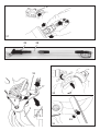
Registrazione lame
• Svitare il dado (14).
• Avvitare il perno (15) (non stringere troppo).
• Riavvitare il dado (14).
Affilatura lama mobile
• Ravvivare il filo della sola lama mobile (16) ogni 2 ore di lavoro con l’apposita pietra;
angolo di affilatura: 45°.
Lubrificazione
• Ogni 20 ore versare una goccia di olio sul rivetto (17) della biella (18).
Pulizia lame
• Inserire le lame (3) (fino a coprire il perno) in una miscela di 50% olio e 50% nafta a fine
giornata. Si eviteranno così le incrostazioni provocate dall’umidità del legno.

6 - 40
Pulizia filtro
• Svitare il raccordo (11).
• Pulire il filtro aria (19) ogni 20 ore di lavoro.
• Sostituirlo quando danneggiato.
Pulizia valvole
• Ogni 150 ore di lavoro pulire le valvole procedendo come segue:
Valvola azionamento
• togliere la protezione (5);
• togliere la leva azionamento (6);
• svitare i tappi (8) e (12) con la chiave in dotazione o una pinza per seeger;
• sfilare delicatamente le valvole (20) e (21);
• soffiare aria compressa su valvole e sedi rimontare seguendo la procedura inversa.
ATTENZIONE: Dopo ogni pulizia verificare il corretto funzionamento della
sicura (7). Non usare mai l’attrezzo senza aver rimontato la protezione o
senza la sicura.
Smontaggio delle parti
Per le operazioni di manutenzione, smontare le parti come segue:
Smontaggio protezione (5)
• togliere le spine (4) - (10);
• forzare delicatamente con un cacciavite tra corpo e protezione.
Smontaggio leva azionamento (6)
• forzare delicatamente con un cacciavite tra corpo e leva.
Smontaggio gruppo valvola (13)
• smontare la protezione (5) e la leva (6);
• immorsare il gruppo valvola (13);
• svitare il corpo impugnandolo con le mani (30).
Smontaggio della biella (18)
• tenendo le lame chiuse con una mano (indossare i guanti) infilare un cilindretto di 20
mm di diametro tra corpo forbice (1), biella (18) e lama mobile (3);
• utilizzando un cacciaspine togliere il rivetto (17). Il rivetto non è più utilizzabile.
Smontaggio delle lame (3)
• togliere il rivetto utilizzando un cacciaspine (17);
• svitare il dado (14) ed il perno (15);
• svitare le viti (2).
Smontaggio della sicura manuale (9)
• introdurre un cacciavite nella parte posteriore della sicura (9);
• fare leva e sollevare delicatamente (31).
GUASTI, CAUSE E RIMEDI
Guasti
L'attrezzo non funziona
Verificare lo stato di funzionamento del compressore.
Verificare la posizione della sicura automatica (7).
Verificare la posizione della sicura manuale (9).
7 - 40
L'attrezzo non ha forza
Verificare la pulizia del tubo di alimentazione.
Verificare la pressione del compressore.
Verificare che il perno lame (15) non sia troppo stretto.
Perdite di aria
Sostituire le guarnizioni se danneggiate anche lievemente
1) Con sicura automatica inserita (7): verificare la guarnizione (22).
2) Senza sicura: verificare le guarnizioni (22) (23) (24) (25) (26).
3) Senza sicura e leva azionamento premuta: verificare le guarnizioni (25) (26) (27).
ACCESSORI
Sono disponibili aste di prolunga in lega leggera di varie lunghezze (da 0,5 a 2,5 m) oppure
telescopiche in tre misure (0,7÷1,2 m; 1,1÷2 m; 1,7÷2,8 m).
Per montare la prolunga:
• smontare protezione (5), leva azionamento (6) e gruppo valvola (13);
• togliere la guarnizione (19);
• avvitare a fondo l’asta (28) interponendo l’apposito raccordo (29).
GARANZIA
• I prodotti CAMPAGNOLA S.r.l. vengono garantiti per 1 o 2 anni dall’acquisto a seconda
dell’articolo scelto, risultante dalla data di fattura o da altro documento avente valore
legale.
• La garanzia è valida se l’installazione della macchina e/o attrezzatura e il successivo
impiego avvengono in ottemperanza alle istruzioni contenute nel manuale uso e
manutenzione o a indicazioni scritte fornite dall’assistenza tecnica autorizzata.
• Parti deteriorate o difettose all’origine verranno riparate o sostituite gratuitamente.
• La mano d’opera è esclusa dalla presente garanzia.
• Sono escluse dalla garanzia tutte le parti soggette ad usura (cinghie, filtri, lame,
guarnizioni …) e le spese di trasporto.
• Sono esclusi dalla garanzia eventuali costi di d’intervento dei nostri tecnici (sopralluoghi,
smontaggi e rimontaggi) per anomalie di funzionamento.
• L’assitenza tecnica valuterà caso per caso, a proprio insindacabile giudizio, quali interventi
possano essere eseguiti in garanzia.
• La garanzia esclude qualsiasi responsabilità per danni diretti o indiretti a persone e/o a
cose, causati da uso o manutenzione inadeguati del compressore e/o delle attrezzature,
ed è limitata ai soli difetti di fabbricazione.
• La garanzia decade in caso di manomissione e/o modifiche (anche lievi) e di impiego di
ricambi non originali.
• È esclusa in ogni caso la sostituzione dell’attrezzatura.
ATTENZIONE!
All’atto della richiesta di riparazione in garanzia, in accordo con le disposizioni
sopra citate, il prodotto da riparare deve essere sempre accompagnato dal
certificato di garanzia correttamente compilato, con allegata rispettiva prova
d’acquisto (fattura o altro documento avente valore legale).

8 - 40
GENERAL
• This manual is supplied with the pruning shears. Keep it with the utmost care.
• No part of this manual can be reproduced or transmitted in any form or by any means
without written permission by the manufacturer.
• The company reserves the right to make changes in its products at any time and without
prior notice.
NOTE: In order to better understand the Use & Maintenance Manual, turn the
cover pages outwards. This will allow you to refer to the drawings and text at
the same time.
WARNING
General
Carefully read this manual before using tool.
The manufacturer shall not be held responsible for any damage caused by improper use
of the shears. The shears must be used only for the purpose they were expressly created
for (see the "Product Description" paragraph).
Use only original spare parts. The manufacturer will not be held responsible for damage
caused by the use of non-original spare parts as well as modifications and servicing of the
tool by unauthorized persons.
Special instructions
• Before starting any operations and while using the tool, always make sure there is a
safe distance between you and other people, animals or things. Make sure that hazard-
ous situations are not created.
• Do not use the tool in places or situations where you may lose your balance.
• Keep the hand which is not gripping the handle away (see figs. A & B).

8 - 40
GENERAL
• This manual is supplied with the pruning shears. Keep it with the utmost care.
• No part of this manual can be reproduced or transmitted in any form or by any means
without written permission by the manufacturer.
• The company reserves the right to make changes in its products at any time and without
prior notice.
NOTE: In order to better understand the Use & Maintenance Manual, turn the
cover pages outwards. This will allow you to refer to the drawings and text at
the same time.
INTRODUCING THE MANUFACTURER
The vast manufacturing expertise and the ability to meet all specific customer’s require-
ments have led CAMPAGNOLA S.r.l. to become the world leader of pruning and harvesting
equipment. Its brand name is known world-wide being a sign of advanced design, sturdi-
ness and reliability.
Over sixty percent of the products are sold abroad. The company provides an extended
sales network, employs highly qualified personnel and offers a wide range of products:
• battery operated electronic pruning shears;
• pruning shears (which can also be connected to various extension poles);
• pneumatic and motor-driven tools for olive and coffee harvesting and for fruit-thinning;
• hedge trimmers, bush cutters and chain saws;
• motorcompressors, hand towed or self-propelled, and PTO shaft driven compressors;
• oil mills.
The products are the right solution to all your problems since they are:
• very easy to handle and use;
• extremely versatile;
• made of high quality material only;
• sturdy and reliable;
• superbly designed.
WARNING
General
Carefully read this manual before using tool.
The manufacturer shall not be held responsible for any damage caused by improper use
of the shears. The shears must be used only for the purpose they were expressly created
for (see the "Product Description" paragraph).
Use only original spare parts. The manufacturer will not be held responsible for damage
caused by the use of non-original spare parts as well as modifications and servicing of the
tool by unauthorized persons.
Special instructions
• Before starting any operations and while using the tool, always make sure there is a
safe distance between you and other people, animals or things. Make sure that hazard-
ous situations are not created.
• Do not use the tool in places or situations where you may lose your balance.
• Keep the hand which is not gripping the handle away (see figs. A & B).
9 - 40
• Never remove, alter or damage any parts or safety devices of the units.
• Set the pressure to 10 bar.
• When the tool is connected to the air line but is not being used, make sure the safety
catch (7) is engaged.
• Always check the efficiency of the safety catch (7) of the lever (6).
• All the maintenance operations which are not described in the manual must be carried
out by an authorized service shop.
• Before performing any maintenance, put the safety catch (7) on and disconnect the air
hose.
WARNING: When transporting the “Super Star” shears always disconnect the
supply hose.
Precautions
WARNING: The manufacturer declines all responsibilities if the precautions
below are not taken.
Results of the tests made by law
WARNING: Risks due to the operator’s contact with the noise and vibrations
of the machine or tool.
1) NOISE LEVEL
Continuous sound pressure level A in the working place, measured according to
the UNI EN ISO 3744 regulations:
LpA
eq
= 87 dBA
The levels measured at the various auxiliary equipment are high as they exceed
the set reference limit LpA
eq
= 70 dBA.
270193 270194
B
A

10 - 40
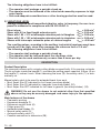
The following obligations have to be fulfilled:
• The operator shall undergo a periodic check up.
• The operator must be informed of the risks faced caused by exposure to high
noise levels.
• Safe and adequate sound barriers or other hearing protection must be used.
2) VIBRATIONS LEVEL
Average weighted hand-transmitted vibration value, in frequency, the user is ex-
posed to measured in compliance with EN ISO 5349/1-2:
Direct shear a
heq
= 5.06 m/s
2
Shear with 0.5 m fixed length extension pole a
heq
= 3.95 m/s
2
Shear with 1.85 ÷ 3.15 m telescopic extension pole in fibreglass a
heq
= 2.80 m/s
2
Shear with 1.25 ÷ 1.95 m telescopic extension pole in aluminium a
heq
= 2.80 m/s
2
Shears with telescopic extension poles of various lengths a
heq
= <2.50 m/s
2
The resulting values, according to the auxiliary tools which have been used, have
turned out to be high, since they overcome the reference limit of 2.5 m/s
2
.
The following obligations have to be fulfilled:
• The operator shall undergo a periodic check up.
• The operator shall be informed about the vibrations risks.
• The tool can be used continuously no more than 6 hours per day.
DESCRIPTION
Product Description
The pneumatic shears with a single cutting blade are specifically fit for pruning orchards.
The air cylinder inside the handle (1) provides the cutting power required. A lever (6) on
the handle (1) makes it work. When releasing the lever (6), the safety catch (7) is auto-
matically on.
Manual safety catch to be used for extended break from work.
• Mod. Super Star SF indicated for fruit trees (one sharp blade).
• Mod. Super Star SV indicated for vineyards (one sharp blade) (32).
• Mod. Super Star SDT indicated for fruit trees in general (two sharp blades ) (33).
WARNING! Do not use the shears to cut material other than that specified
above as they may be severely damaged and cause injury to the operator.
Main features of the shears
• Pneumatic working.
• Ergonomic handgrip (1).
• Ergonomic control lever (6).
• Finger guard (5).
• Hardened steel blades (3).
• Manual safety catch (9).
• Automatic safety catch (7).
• Possible connection to extensions (28).

10 - 40
The following obligations have to be fulfilled:
• The operator shall undergo a periodic check up.
• The operator must be informed of the risks faced caused by exposure to high
noise levels.
• Safe and adequate sound barriers or other hearing protection must be used.
2) VIBRATIONS LEVEL
Average weighted hand-transmitted vibration value, in frequency, the user is ex-
posed to measured in compliance with EN ISO 5349/1-2:
Direct shear a
heq
= 5.06 m/s
2
Shear with 0.5 m fixed length extension pole a
heq
= 3.95 m/s
2
Shear with 1.85 ÷ 3.15 m telescopic extension pole in fibreglass a
heq
= 2.80 m/s
2
Shear with 1.25 ÷ 1.95 m telescopic extension pole in aluminium a
heq
= 2.80 m/s
2
Shears with telescopic extension poles of various lengths a
heq
= <2.50 m/s
2
The resulting values, according to the auxiliary tools which have been used, have
turned out to be high, since they overcome the reference limit of 2.5 m/s
2
.
The following obligations have to be fulfilled:
• The operator shall undergo a periodic check up.
• The operator shall be informed about the vibrations risks.
• The tool can be used continuously no more than 6 hours per day.
DESCRIPTION
Product Description
The pneumatic shears with a single cutting blade are specifically fit for pruning orchards.
The air cylinder inside the handle (1) provides the cutting power required. A lever (6) on
the handle (1) makes it work. When releasing the lever (6), the safety catch (7) is auto-
matically on.
Manual safety catch to be used for extended break from work.
• Mod. Super Star SF indicated for fruit trees (one sharp blade).
• Mod. Super Star SV indicated for vineyards (one sharp blade) (32).
• Mod. Super Star SDT indicated for fruit trees in general (two sharp blades ) (33).
WARNING! Do not use the shears to cut material other than that specified
above as they may be severely damaged and cause injury to the operator.
Main features of the shears
• Pneumatic working.
• Ergonomic handgrip (1).
• Ergonomic control lever (6).
• Finger guard (5).
• Hardened steel blades (3).
• Manual safety catch (9).
• Automatic safety catch (7).
• Possible connection to extensions (28).
11 - 40
Specifications
• Handgrip diameter ................................................................................................. 48 mm
• Cutting diameter .................................................................................................... 32 mm
• Working pressure: ............................................................................... 1000 kPa (10 bar)
• Max. air consumption ....................................................................................... Nl/min 0.9
• Weight .............................................................................................................. 600 grams
OPERATION
Controls
• Control lever (6): gently press the control lever to make the shear cut.
• Safety catch (7): it is automatically on as soon as the control lever (6) is released.
WARNING: Always check the perfect functioning of the safety devices.
Air connections
• Make sure the safety catch (7) is on.
• Set the compressor to a pressure of 10 bar.
• Screw on a 1/4" quick coupling (11).
• Check the air hose for the presence of dirt or impurities and then connect it.
MAINTENANCE
WARNING: All the maintenance operations which are not described in the
manual must be carried out by an authorized service shop.
WARNING: Pay attention to parts with sharp cutting edges. For any interven-
tion, use adequate gloves.
General
Before performing any maintenance:
• The safety catch (7) must be on.
• Disconnect the air hose.
Adjusting the blades
• Unscrew the nut (14).
• Screw the pin (15) (not too tight).
• Screw the nut (14) tight again.
Sharpening the mobile blade
• Only the cutting edge of the mobile blade (16) is to be sharpened every 2 working hours
using the proper stone; sharpening angle: 45°.
Lubrication
• Every 20 hours, pour a drop of oil on the rivet (17) of the link (18).
Cleaning the blades
• Dip the blades (3) (until the pin is covered) into a mixture of 50% oil and 50% diesel fuel
at the end of the work day. This will avoid deposits due to the wood moisture.

12 - 40
Cleaning the filter
• Unscrew the coupling (11).
• Clean the air filter (19) every 20 working hours.
• Replace the filter when damaged.
Cleaning the valves
• Clean the valves every 150 working hours by following these instructions:
Drive valve
• Remove the guard (5).
• Remove the lever (6).
• Unscrew the caps (8) and (12) with the wrench supplied or with a gripper for snap rings.
• Gently pull out the valves (20) and (21).
• Blow compressed air onto the valves and their seats; reassemble the parts by follow-
ing the instructions in reverse
WARNING: After cleaning the valve, check the safety catch (7) for proper func-
tioning. Never use the tool without first installing the guard or if the safety
catch is off.
Removing the parts
When maintenance is required, remove the parts following these instructions:
Removing the guard (5)
• Remove the pins (4) - (10).
• Using a screwdriver, exert a slight pressure between the body and the guard.
Removing the control lever (6)
• Using a screwdriver, exert a slight pressure between the body and the lever.
Removing the valve group (13)
• Remove the guard (5) and the lever (6).
• Clamp the valve assembly (13).
• Unscrew the body with your hands (30).
Removing the connecting rod (18)
• Keeping the blades closed with your hand (always wear heavy gloves) put a 20 mm
ø pin among the shear body (1), the connecting rod (18) and the mobile blade (3).
• Use a pindriver to remove the rivet (17). The rivet cannot be re-used.
Removing the blades (3)
• Remove the rivet (17) by using a pindriver.
• Remove the nut (14) and the pin (15).
• Loosen the screws (2).
Removing the manual safety catch (9)
• Insert a screwdriver into the rear part of the safety catch (9).
• Lever and carefully lift the catch (31).
TROUBLESHOOTING
Faults
The tool do not work
Check the compressor for proper functioning.
Check the position of the automatic safety catch (7).
Check the position of the manual safety catch (9).
13 - 40
The tool do not have enough cutting power
Make sure the air supply hose is clean.
Check the pressure in the compressor unit.
Make sure the blade (15) pivot pin is not too tight.
Air leaks
Replace the seals even if only slightly damaged
1) With the automatic safety catch (7) on: check the seal (22).
2) With the safety catch off: check the seals (22, 23, 24, 25, 26).
3) With the safety catch off and the control lever pressed: check the seals (25, 26, 27).
ACCESSORIES
Light-alloy extensions are available in various lengths (from 0.5 to 2.5 m). Telescopic ex-
tensions are also available in three different sizes (0.7÷1.2 m, 1.1÷2 m, 1.7÷2.8 m).
To connect the extension:
• Remove the guard (5), the control lever (6) and the valve assembly (13).
• Remove the seal (19).
• Put on the fitting (28) and then fully tighten the extension (29).
WARRANTY
• The tools and machines are guaranteed for 1 or\HDUVGHSHQGLQJRQWKHNLQGRI
product, starting from their purchase date indicated inWKHLQYRLFHRULQDQ\RWKHU
document with legal value.
• The warranty is to be considered valid only if the installation and use of the compressor
and/or tools have been carried out according to the instructions indicated in the Use and
Maintenance Manual or to instructions written by the Authorized Service Point person-
nel (Service program).
• Originally faulty parts will be repaired or replaced free of charge.
• The purchaser shall pay for the labour and transport costs.
• All the parts subject to wear (belts, filters, blades, seals, etc.) are not subject to the warranty.
• The eventual costs of intervention (inspections, disassembling and assembling
operations), caused by wrong working which was not due to manufacture faults, are not
included in the warranty.
• Replacements or repairs of faulty equipment, when warranty is claimed by the users, can
only be authorized by accredited Service Points personnel and their decision is final.
• The Company shall not be held responsible for any injury or damage caused to people,
animals or things, due to improper use or maintenance of the compressor and/or tools.
The warranty is limited to the manufacture defects.
• The warranty is lost in case of tampering and /or even small changes and in case of use
of non-original spare parts.
• In any case the replacement of the tool is excluded.
WARNING: For warranty claims, according to the above mentioned points, it
is necessary to enclose the properly filled-in warranty card and the corre-
sponding purchase proof with date of purchase (invoice or any other docu-
ment with legal value).

14 - 40
ALLGEMEINES
• Das vorliegende Handbuch ist integrierter Bestandteil der Scherenlieferung.
• Ohne schriftliche Genehmigung von der Herstellerfirma darf das Handbuch nicht zur
Einsichtnahme an Dritte ausgehändigt werden.
• Alle Vervielfältigungsrechte des Handbuches sind der Herstellerfirma vorbehalten.
• Die Herstellerfirma behält sich das Recht auf Änderungen vor, ohne dies Kunden mitteilen
zu müssen, die bereits in Besitz ähnlicher Modelle sind.
ANMERKUNG: Als Hilfe zum besseren Verständnis der Gebrauchs- und
Wartungsanweisung kann man die Umschlagsseiten nach außen hin öffnen,
um gleichzeitig den Hinweisen der Zeichnung und denen des Textes zu folgen.
UNFALLVERHÜTUNGSVORSCHRIFTEN
Allgemeines
Bevor man mit dem Gerät arbeitet, muss zunächst das folgende Handbuch aufmerksam
durchgelesen werden.
Die Herstellerfirma haftet nicht für Schäden, die durch einen unzweckmäßigen und
unsachmäßigen Einsatz der Schere entstehen (siehe Kap. “Beschreibung des Produkts”).
Die Herstellerfirma haftet nicht für den Gebrauch von nicht originalen Ersatzteilen sowie
für von unbefugten Personen ausgeführten Änderungen oder Eingriffen am Werkzeug.
Vorsichtsmaßnahmen
• Vor und während der Ausführung der Arbeiten muss sichergestellt werden, dass der
Gebrauch des Geräts keine Gefahren für Personen, Tiere und Sachgegenstände erzeugt.
• Wenn kein sicherer Stand bzw. eine prekäre Gleichgewichtslage vorliegt darf das Gerät
nicht verwendet werden.

14 - 40
ALLGEMEINES
• Das vorliegende Handbuch ist integrierter Bestandteil der Scherenlieferung.
• Ohne schriftliche Genehmigung von der Herstellerfirma darf das Handbuch nicht zur
Einsichtnahme an Dritte ausgehändigt werden.
• Alle Vervielfältigungsrechte des Handbuches sind der Herstellerfirma vorbehalten.
• Die Herstellerfirma behält sich das Recht auf Änderungen vor, ohne dies Kunden mitteilen
zu müssen, die bereits in Besitz ähnlicher Modelle sind.
ANMERKUNG: Als Hilfe zum besseren Verständnis der Gebrauchs- und
Wartungsanweisung kann man die Umschlagsseiten nach außen hin öffnen,
um gleichzeitig den Hinweisen der Zeichnung und denen des Textes zu folgen.
VORSTELLUNG DES UNTERNEHMENS
Die Fähigkeit, den Marktanforderungen mit gleichzeitig spezifischen und dynamischen
Antworten entgegenzukommen, sowie die Gewährleistung einer umfassenden Fachkenntnis
haben aus der Herstellerfirma den weltweiten Führer für Entwurf, Erzeugung und Realisierung
von pneumatischen Geräten für Baumschnitt, Oliven- und Kaffee-Ernte gemacht.
Mit einer zu 60% auf den ausländischen Markt ausgerichteten Produktion und einem
effizienten Vertriebs- und Kundendienstnetz, das hochqualifiziertes Personal beschäftigt,
wird eine breitgefächerte Produktpalette angeboten:
• Mit schneidenden Oberflächen.
• Baumschnittscheren (auch mit Verlängerung).
• Pneumatische und Motorgeräte für die Oliven- und Kaffee-Ernte und für die
Fruchtausdünnung.
• Heckenscheren, Freischneider und Kettensägen.
• Fahrbare und selbstfahrende Motorkompressoren und 3-Punkt-Kompressoren.
• Ölpressen.
Die Gründe für eine Entscheidung können wie folgt zusammengefaßt werden:
• Praktische Handhabung der Produkte.
• Vielseitige Einsatzmöglichkeiten.
• Höchste Qualität der verwendeten Materialien.
• Zuverlässigkeit.
• Produktplanungstechnik.
UNFALLVERHÜTUNGSVORSCHRIFTEN
Allgemeines
Bevor man mit dem Gerät arbeitet, muss zunächst das folgende Handbuch aufmerksam
durchgelesen werden.
Die Herstellerfirma haftet nicht für Schäden, die durch einen unzweckmäßigen und
unsachmäßigen Einsatz der Schere entstehen (siehe Kap. “Beschreibung des Produkts”).
Die Herstellerfirma haftet nicht für den Gebrauch von nicht originalen Ersatzteilen sowie
für von unbefugten Personen ausgeführten Änderungen oder Eingriffen am Werkzeug.
Vorsichtsmaßnahmen
• Vor und während der Ausführung der Arbeiten muss sichergestellt werden, dass der
Gebrauch des Geräts keine Gefahren für Personen, Tiere und Sachgegenstände erzeugt.
• Wenn kein sicherer Stand bzw. eine prekäre Gleichgewichtslage vorliegt darf das Gerät
nicht verwendet werden.
15 - 40
• Die Hand, die nicht zum Festhalten des Geräts genutzt werden, muss stets in
entsprechender Entfernung zum Gerät gehalten werden (siehe Abb. A und B).
• Keine Teile, insbesonders jene, die die Gebrauchssicherheit gewährleisten, verändern,
entfernen oder beschädigen.
• Den Kompressor für die Versorgungsluft auf einen Wert von 10 Bar einstellen.
• Wenn das Gerät zwar mit Druckluft gespeist aber vorübergehend nicht genutzt wird,
muss kontrolliert werden, ob sich die automatische Sicherung (7) eingeschaltet hat.
• Immer die Leistungsfähigkeit der Sicherheitsvorrichtung (7) auf dem Betätigungshebel
(6) kontrollieren.
• Alle Wartungsarbeiten des Geräts, die von den in der Gebrauchs- und Wartungsanleitung
genannten Vorgängen abweichen, müssen einer darauf spezialisierten Werkstatt
anvertraut werden.
• Bevor irgendeine Wartungsarbeit ausgeführt wird, ist die Sicherheitsvorrichtung (7) zu
aktivieren und die Luftzuführung zu unterbrechen.
ACHTUNG: Der Transport der Schere “Super Star” muß immer bei nicht
angeschlossener Zufuhrleitung ausgeführt werden.
Anweisungen
ACHTUNG: Der Hersteller übernimmt keine Verantwortung, die auf der
Nichteinhaltung folgender Angaben beruht.
Ergebnisse der Prüfungen nach dem Gesetz
ACHTUNG: Gefahren des Bedieners wegen des Lärmes und der Vibrationen der Geräte.
1) LÄRM-NIVEAU
Niveau vom durchgehenden Lärmdruck A am Arbeitsplatz. Es wird nach den
Rechtsvorschriften UNI EN ISO 3744 gemessen:
LpA
eq
= 87 dBA
Mit unterschiedlichen Hilfsausrüstungen wurden für die gleichen Werterhebungen
hohe Ergebnisse festgestellt, d.h. der festgelegte Bezugsgrenzwert wurde
überschritten LpA
eq
= 70 dBA.
270193 270194
B
A

16 - 40
Deswegen soll man das Folgende durchführen:
• Der Bediener soll sich einer periodischen Gesundheitskontrolle unterziehen.
• Der Bediener muss über die Risiken informiert werden, denen er durch den
hohen Schallpegel ausgesetzt wird.
• Das Tragen von lärmdämmenden Ohrenschützern oder anderer Mitteln als
Gehörschutz ist Pflicht.
2) VIBRATIONEN-NIVEAU
Als durchschnittlicher, quadratischer, in Frequenz gewogener und auf das Hand-
Arm System übertragener Beschleunigungswert, dem der Bediener ausgesetzt
wird, hat sich gemäß EN ISO 5349/1-2 folgender Wert ergeben:
Direkt genutzte Schere a
heq
= 5,06 m/s
2
Schere mit fester Stange m 0,5 a
heq
= 3,95 m/s
2
Schere mit teleskopischer Fiberglas-Stange m 1,85 ÷ 3,15 a
heq
= 2,80 m/s
2
Schere mit teleskopischer Aluminium-Stange m 1,25 ÷ 1,95 a
heq
= 2,80 m/s
2
Scheren mit teleskopischen Stangen von unterschiedlicher Länge a
heq
= <2,50 m/s
2
Die nachgeprüften Werte bei der Verwendung von Nebengeräten sind hoch, weil
sie die Beziehungsgrenze von 2,5 m/s
2
überschreiten.
Deswegen soll man das Folgende durchführen:
• Der Bediener soll sich einer periodischen Gesundheitskontrolle unterziehen.
• Der Bediener soll über die Gefahren wegen der Vibrationen informiert werden.
• Die maximal zulässige Arbeitsdauer begrenzt sich auf täglich 6 ununterbrochene
Arbeitsstunden.
BESCHREIBUNG
Beschreibung des Produkts:
Pneumatische Schere, mit Schneidemesser für das Beschneiden von Obstbäumen. Die
Schneidkraft wird durch einen im Griff angebrachten Druckluftzylinder erzeugt, der über
eine Druckluftleitung versorgt wird und mit einem am Griff (1) angebrachten Hebel (6) betätigt
werden kann.
Auf dem Betätigungshebel (6) ist die Sicherheitsvorrichtung (7) angebracht, die sich bei
dessen Einsatz automatisch aktiviert.
Manuelle Sicherheitsvorrichtung, die bei langen Arbeitspausen einzusetzen ist.
• Mod. Super Star SF für Obstbäume (eine Schneideklinge).
• Mod. Super Star SV für Weinreben (eine Schneideklinge) (32).
• Mod. Super Star SDT für Obstbäume im allgemeinen (zwei Schneideklingen) (33).
ACHTUNG: Falls die Schere zur Beschneidung von Materialien, die nicht oben
aufgeführt sind, verwendet wird, kann sowohl das Gerät ernsthaft beschädigt
werden als auch die eigene Sicherheit beeinträchtigt werden.
Eigenschaften
• Pneumatischer Betrieb.
• Ergonomischer Griff aus Kunststoff (1).
• Ergonomischer Betätigungshebel (6).
• Fingerschutz (5).
• Messer aus gehärtetem Stahl (3).
• Manuelle Sicherheitsvorrichtung (9).
• Automatische Sicherheitsvorrichtung (7).
• Möglichkeit zur Anbringung an Verlängerung (28).
17 - 40
Technische Daten
• Griffdurchmesser: .................................................................................................. 48 mm
• Schneidbarer Durchmesser: ................................................................................. 32 mm
• Betriebsdruck: ...................................................................................... 1000 kPa (10 bar)
• Max. Luftverbrauch: .......................................................................................... NI/min 0,9
• Gewicht: .................................................................................................................. 600 gr
FUNKTIONSWEISE
Bedienungselemente
• Steuerhebel (6): Bei leichtem Drücken schneidet die Schere.
• Sicherheitsvorrichtung (7): Wird automatisch bei Einsatz des Betätigungshebels aktiviert.
ACHTUNG: Es muß immer kontrolliert werden, daß sich die Sicherheitselemente
in perfektem Funktionszustand befinden.
Anschluß an die Luftzufürung
• Kontrollieren, daß die Sicherheitsvorrichtung (7) aktiviert ist.
• Den Kompressor auf 10 Bar einstellen.
• Einen Schnellanschluß 1/4" aufschrauben (11).
• Den Versorgungsschlauch anschließen. Sich zuvor vergewissern, daß dieser nicht
verschmutzt ist.
WARTUNG
ACHTUNG:Alle Wartungsarbeiten an der Schere, die nicht in der Gebrauchs-
und Wartungsanleitung genannt werden, müssen von einem spezialisierten
Kundendienstbetrieb ausgeführt werden.
ACHTUNG: Zu beachtende Warnung vor schneidenden Teilen. Schutzhandschuhe
verwenden.
Allgemeines
Bevor man irgendeinen Wartungseingriff durchführt, muß man
• Die Sicherheitsvorrichtung aktivieren (7).
• Den Versorgungsschlauch herausziehen.
Messereinstellung
• Die Mutter (14) lösen.
• Den Stift (15) einschrauben (nicht zu fest anziehen).
• Die Mutter wieder anziehen (14).
Schleifen des beweglichen Messers
• Die Kante des beweglichen Messers (16) alle 2 Arbeitsstunden mit dem dafür
vorgesehenen Stein nachschleifen. Schleifwinkel: 45°.
Schmierung
• Ein Öltropfen auf den Niet (17) des Pleuels (18) gießen.
Reinigung der Messer
• Am Ende des Arbeitstages die Messer (3) in eine Mischung aus 50% Öl und 50%
Dieselkraftstoff tauchen, bis der Bolzen bedeckt ist. Auf diese Weise vermeidet man
durch die Feuchtigkeit des Holzes verursachte Verkrustungen.
La page est en cours de chargement...
La page est en cours de chargement...
La page est en cours de chargement...
La page est en cours de chargement...
La page est en cours de chargement...
La page est en cours de chargement...
La page est en cours de chargement...
La page est en cours de chargement...
La page est en cours de chargement...
La page est en cours de chargement...
La page est en cours de chargement...
La page est en cours de chargement...
La page est en cours de chargement...
La page est en cours de chargement...
La page est en cours de chargement...
La page est en cours de chargement...
La page est en cours de chargement...
La page est en cours de chargement...
La page est en cours de chargement...
La page est en cours de chargement...
La page est en cours de chargement...
La page est en cours de chargement...
La page est en cours de chargement...
La page est en cours de chargement...
-
 1
1
-
 2
2
-
 3
3
-
 4
4
-
 5
5
-
 6
6
-
 7
7
-
 8
8
-
 9
9
-
 10
10
-
 11
11
-
 12
12
-
 13
13
-
 14
14
-
 15
15
-
 16
16
-
 17
17
-
 18
18
-
 19
19
-
 20
20
-
 21
21
-
 22
22
-
 23
23
-
 24
24
-
 25
25
-
 26
26
-
 27
27
-
 28
28
-
 29
29
-
 30
30
-
 31
31
-
 32
32
-
 33
33
-
 34
34
-
 35
35
-
 36
36
-
 37
37
-
 38
38
-
 39
39
-
 40
40
-
 41
41
-
 42
42
-
 43
43
-
 44
44


CAMPAGNOLA 0310.0123 forbice S. STAR Doppio taglio Le manuel du propriétaire
- Catégorie
- Outils électroportatifs
- Taper
- Le manuel du propriétaire
dans d''autres langues
Documents connexes
-
CAMPAGNOLA 0310.0104 forbice F4 CAMP. Le manuel du propriétaire
-
-
-
-
-
-
-
-
-