Powerfist 8871626 Le manuel du propriétaire
- Catégorie
- Souffleuses à neige
- Taper
- Le manuel du propriétaire

V1.0 8871626
Please read and understand all instructions before use. Retain this manual for
future reference.

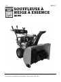
8871626 28 in. Gas Snow Thrower V1.0
2 For technical questions call 1-800-665-8685
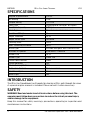
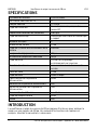
SPECIFICATIONS
Engine Displacement
252 cc
HP Rating
9 HP
Torque Rating
11.5 ft-lb
Fuel Type
Pump octane rating 87 or higher
Fuel Tank Capacity
0.85 gal.
Start Type
Recoil start and electric start
Number of Stages
2
Auger Diameter
13 in.
Auger Drive Type
Serrated
Clearing Path
28 in.
Max. Throwing Distance
40 ft
Drive Type
Friction and gear, belt transmission
Number of Speeds
6 forward, 2 reverse
Wheel Size
14 in.
Wheel Type
Snow tire
Chute Construction
Steel
Chute Rotation
Yes
Chute Turning Radius
180°
Deflection Control
Rocker control
Skid Shoe Type
Steel
Head Light
Yes
INTRODUCTION
The 28 in. Gas Snowblower has 8 speeds for clearing a 28 in. path through the snow.
A separate engine manual is included. Please consult it when necessary.
SAFETY
WARNING! Read and understand all instructions before using this tool. The
operator must follow basic precautions to reduce the risk of personal injury
and/or damage to the equipment.
Keep this manual for safety warnings, precautions, operating or inspection and
maintenance instructions.

V1.0 28 in. Gas Snow Thrower 8871626
Visit www.princessauto.com for more information 3
HAZARD DEFINITIONS
Please familiarize yourself with the hazard notices found in this manual. A
notice is an alert that there is a possibility of property damage, injury or death
if certain instructions are not followed.
DANGER! This notice indicates an immediate and specific hazard that will
result in severe personal injury or death if the proper
precautions are not taken.
WARNING! This notice indicates a specific hazard or unsafe practice that
could result in severe personal injury or death if the proper
precautions are not taken.
CAUTION! This notice indicates a potentially hazardous situation that may
result in minor or moderate injury if proper practices are not taken.
NOTICE! This notice indicates that a specific hazard or unsafe practice will
result in equipment or property damage, but not personal injury.
WORK AREA
1. Operate in a safe work environment. Keep your work area clean, well-lit
and free of distractions. Place lights so you are not working in a shadow.
2. Keep anyone not wearing the appropriate safety equipment away from the
work area.
3. Store unused tools properly in a safe and dry location to prevent rust or
damage. Lock tools away and keep out of the reach of children.
4. Do not install or use in the presence of flammable gases, dust or liquids.
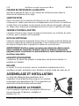
PERSONAL SAFETY
WARNING! Wear personal protective equipment approved by the Canadian
Standards Association (CSA) or American National Standards Institute (ANSI).
PERSONAL PROTECTIVE EQUIPMENT
1. Always wear impact safety goggles that provide front and side protection
for the eyes. Eye protection equipment should comply with CSA Z94.3-07
or ANSI Z87.1 standards based on the type of work performed.
2. Wear gloves that provide protection based on the work materials or to
reduce the effects of tool vibration.
a. Do not wear gloves when operating a tool that can snag the material
and pull the hand into the tool.

8871626 28 in. Gas Snow Thrower V1.0
4 For technical questions call 1-800-665-8685
3. Wear protective clothing designed for the work environment and tool.
4. Non-skid footwear is recommended to maintain footing and balance in the
work environment.
PERSONAL PRECAUTIONS
Control the tool, personal movement and the work environment to avoid
personal injury or damage to tool.
1. Do not operate any tool when tired or under the influence of drugs,
alcohol or medications.
2. Avoid wearing clothes or jewelry that can become entangled with the
moving parts of a tool. Keep long hair covered or bound.
3. Do not overreach when operating a tool. Proper footing and balance
enables better control in unexpected situations.
4. Securely hold this tool using both hands. Using a tool with only one hand
can result in loss of control.
SPECIFIC SAFETY PRECAUTIONS
WARNING! DO NOT let comfort or familiarity with product (gained from
repeated use) replace strict adherence to the tool safety rules. If you use this
tool unsafely or incorrectly, you can suffer serious personal injury.
1. Use the correct tool for the job. This tool was designed for a specific function.
Do not modify or alter this tool or use it for an unintended purpose.
2. Do not use the tool if any parts are damage broken or misplaced. Repair or
replace the parts.
3. Check the area for objects or obstruction that can damage the
snowblower’s blades or be thrown out the chute or housing. Remove
objects from the area and avoid obstructions.
4. Be aware of your surroundings. The tool’s noise can mask approaching
people, pets and vehicles.
5. Shut off the engine before attempting to remove debris from the
snowblower’s blades or chute. Use tools to remove the debris instead of
your hands.
6. Direct the discharge chute away from bystanders. Ejected snow and
hidden objects can injure a bystander.

V1.0 28 in. Gas Snow Thrower 8871626
Visit www.princessauto.com for more information 5
UNPACKING
WARNING! Do not operate the tool if any part is missing. Replace the missing
part before operating. Failure to do so could result in a malfunction and
personal injury.
Remove the parts and accessories from the packaging and inspect for damage.
Make sure that all items in the contents are included.
Contents:
• Snowblower
• Lower Handle
• One Pair of Skid Shoes with Hardware
• 4 Extra Shear Pins and Locknuts
• Discharge Chute Assembly
• Chute Rotation Handle
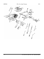
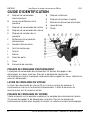
IDENTIFICATION KEY
A Drive Control Handle
B Chute Deflector Lever
C Auger Control Handle
D Speed Control Handle
E Chute Rotation Handle
F Discharge Chute Deflector
G Discharge Chute
H Clean-out Tool
I Auger
J Shave Plate
K Skid Shoe
L Tire
M Belt Cover
N Lower Handle
O Recoil Starter Handle
P Electric Start Button
Q Oil Dipstick
R Headlight
DRIVE CONTROL HANDLE
The drive control handle (A) engages and disengages the drive wheels. Squeeze
the drive control handle against the upper handle to engage the wheels;
release to disengage.

8871626 28 in. Gas Snow Thrower V1.0
6 For technical questions call 1-800-665-8685
SPEED CONTROL LEVER
The speed control lever (D) is located in the center of the panel. It controls the drive
speed and direction of travel. It can be moved into six positions, 6 forward, 2 reverse.
AUGER CONTROL HANDLE
Located on the left side of the upper handle, the auger control handle (C)
engages and disengages the augers. Squeeze the auger control handle to
engage the augers; release to disengage the augers.
CHUTE ROTATION HANDLE
Rotate the handle (E) clockwise or counter-clockwise to adjust snow
discharge direction.
SKID SHOE
Position the shoes (K) based on the surface conditions. Adjust upward for hard-
packed snow. Adjust downward when operating on gravel or crushed rock surfaces.
AUGERS AND IMPELLER
The augers (I) rotate to cut snow and direct it into the impeller housing to be
discharged out the chute.
CLEAN-OUT TOOL
The chute clean-out tool (H) is conveniently fastened to the rear of the auger
housing with a mounting clip. It is used to clean the chute assembly and chute
opening when snow and ice become lodged.
WARNING! Never use your hands to clear a clogged chute assembly. Shut off
engine and remain behind handles until all moving parts have stopped before
unclogging.
DISCHARGE CHUTE
The chute (G) provides a discharge path for snow being thrown. The chute
is adjustable.
SHAVE PLATE
The shave plate (J) maintains contact with pavement as the snowblower is
propelled, allowing snow close to pavement's surface to be discharged.
ASSEMBLY & INSTALLATION
Letter references in parenthesis (A) refer to the included Identification Key.
Dashed numbers in parenthesis (Fig. 1-1) refer to a specific point in an
illustration or image.

V1.0 28 in. Gas Snow Thrower 8871626
Visit www.princessauto.com for more information 7
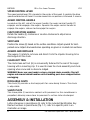
HANDLE ASSEMBLY
Attach the upper handle to the lower handle using
(4) knobs, washers and bolts (Fig. 1-1).
NOTICE! Do not bend or kink the control cables. The
cables should be routed under the handle assembly
and not wrapped around the handle or knobs. The
cables must move freely and not bind.
CHUTE ASSEMBLY
1. Install the discharge chute onto the chute flange on
the auger housing. The chute only rests on the flange.
2. Slide the chute rod through the mounting hole on the
left upper handle (Fig. 2).
3. Attach the chute rotation
bar to the mount bracket
onto the chute housing
using two screws, washers
and locknuts (Fig. 3).
Tighten fasteners securely.
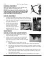
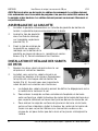
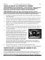
SKID SHOES
INSTALLATION AND ADJUSTMENTS
1. Locate the pair of skid shoes from the parts
bag and remove the bolts.
2. Loosely install the skid shoes using the bolts
and hex nuts as shown on each side of the
auger housing (Fig. 4). Make sure the skid shoe
tip faces out.
a. Adjustment of the skid shoes sets the
height above the ground at which the auger shave plate operates.
b. For clearing snow from concrete, asphalt, and other smooth surfaces,
set the auger shave plate so that the bottom of the plate is just above
the ground.
c. For clearing snow from gravel, dirt, and other rough surfaces set the
auger shave plate slightly above the ground to avoid dirt and gravel
from entering the auger.
d. The optimal height of the plate will vary depending on the type of
Fig. 2
Fig. 3
Fig. 4
Fig. 1
1-1

8871626 28 in. Gas Snow Thrower V1.0
8 For technical questions call 1-800-665-8685
surface being cleared. Surfaces with larger gravel or stones require a
higher shave plate setting.
3. Move the snowblower to a solid, smooth, and level surface.
4. Place a spacer board on the ground underneath the auger shave plate
between the skid shoes. The thickness of the board should be the same as
the height above the ground you wish to raise the auger shave plate. The
skid shoes should not touch the board.
5. With the two (2) nuts loose allow the skid shoe to slide to the ground then
tighten the nuts to secure the skid shoe.
OPERATION
WARNING! Do not place any body part in the chute or auger housing when the
engine is running or control handles are engaged, even if you do not see the
auger or impeller rotating. The auger and impeller rotate at fast speeds which
can cause harm or amputation. Shut the engine off, disengage all control
handles and use the clean-out tool to remove obstructions.
Consult the separate engine manual for instructions on preparation
and operation.
PREPARATION BEFORE EACH USE
1. Consult the separate engine manual for instructions on preparation
and operation.
2. Check all fasteners are tight.
3. Check the tires are properly inflated.
4. Adjust the shave plate for the surface.
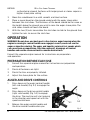
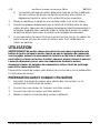
AUGER AND DRIVE CONTROLS
1. Press down on the auger control handle
(left side handle) (Fig. 5-1) to engage the
auger.
2. Press down on the drive control handle
(right side handle) (Fig. 5-2) to engage
the drive. The machine will start moving
in the direction and speed set with the
speed control lever.
3. Release the auger control handle and
the drive control handle when you
Fig. 5
5-1
5-2

V1.0 28 in. Gas Snow Thrower 8871626
Visit www.princessauto.com for more information 9
finish clearing a snow path.
ATTENTION! Release (disengage) the auger and drive control handles before
adjusting the drive speed control lever. Never change the drive speed while
your snowblower is moving, it could damage the drive mechanism.
DRIVE SPEED CONTROL LEVER
Move the drive speed control lever to the desired
speed. There are eight settings: six forward speeds
and two reverse speeds. The forward speed settings
start with 1 as the slowest speed and 6 as the
fastest. Reverse speed has R1 for the slowest
reverse speed and R2 as the faster reverse speed.
There is no neutral drive setting since the drive
control handle must be engaged for movement.
Neutral is achieved when the drive control handle is
disengaged.
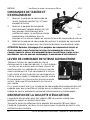
CHUTE DISCHARGE DIRECTION
The discharge chute may be angled across a 180º degree range from right to
left to eject snow in a safe direction. Rotate the chute deflector lever (B) to
adjust the chute’s angle, clockwise for left and counterclockwise for right.
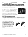
CHUTE DISCHARGE ANGLE
WARNING! Always disengage the drive and
auger control handles before making
adjustments. Make sure the augers are
stopped and the machine is not moving.
The angle of the chute deflector controls
the discharge distance of the snow. Raising
the angle will increase the distance.
Lowering the angle will decrease the
distance.
1. Loosen the knobs on the chute deflector and adjust the chute deflector to
the desired angle (Fig. 7).
2. Retighten the knobs. Do not over-tighten.
Fig. 6
Fig. 7

8871626 28 in. Gas Snow Thrower V1.0
10 For technical questions call 1-800-665-8685
OPERATING YOUR SNOWBLOWER
NOTICE! Do not operate the snowblower if any components freeze in extremely
cold temperatures. Freezing will impair the snowblower’s function and it may
suffer damage if used. Thaw all components before attempting to start the
equipment. Do not thaw with an open flame.
Snow conditions will affect how effective the snowblower will clear the snow
away. Wet or hard-pack snow is more difficult to clear. Remove narrower strips
of snow with more passes at a slower speed. Allow the auger to clear the snow
in the snowblower before stopping.
1. Move the snowblower outside.
2. Consult the engine manual to start the engine. Wait several minutes to
allow the engine to warm up.
3. Adjust the chute direction and angle to the desired direction.
4. Engage the auger control handle (C) to start the augers and impeller.
5. Set the desired direction and speed using the speed control lever (D).
6. Engage the drive control handle (A) and hold the hand grips to direct the
snowblower as you clear a path through the snow.
7. Adjust the chute whenever as you move the snowblower in a
different direction.
CHANGING SPEEDS OR DIRECTION
1. Disengage the drive control handle (A) before changing speeds or
changing direction.
2. Selected the desired speed/direction with the speed control handle (D).
3. Engage the drive control handle.
STOPPING
1. Move the snowblower onto a spot already cleared.
2. Allow the auger and impeller to run another 30 seconds to clear any
remaining snow inside the snowblower.
3. Disengage the auger control handle (C) and wait for the blades to stop.
4. Switch OFF the engine. Consult the engine manual for the complete shut
down procedure.
5. Remove snow from all snowblower surfaces including the auger housing
and chute areas. Use the clean-out tool (H).

V1.0 28 in. Gas Snow Thrower 8871626
Visit www.princessauto.com for more information 11
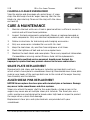
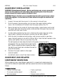
CLEARING A CLOGGED SNOWBLOWER
Stop the engine and disengage all control levers if snow
clogs the discharge chute or augur housing. Wait for the
blades to stop rotating. Clean out the clog with the clean-
out tool (H).
CARE & MAINTENANCE
1. Maintain the tool with care. A tool in good condition is efficient, easier to
control and will have fewer problems.
2. Inspect the tool components periodically. Repair or replace damaged or
worn components. Only use identical replacement parts when servicing.
3. Follow instructions for lubricating and changing accessories.
4. Only use accessories intended for use with this tool.
5. Keep the tool clean, dry and free from oil/grease at all times.
6. Check the tightness of bolt and nuts on a regular basis.
7. Maintain the tool’s labels and name plates. These carry important information.
If unreadable or missing, contact Princess Auto Ltd. for replacements.
WARNING! Only qualified service personnel should repair the tool. An
improperly repaired tool may present a hazard to the user and/or others.
SHAVE PLATE REPLACEMENT
Remove both skid shoes and hardware, including carriage bolts and nuts,
which attach shave plate to snowblower housing. Reassemble new shave plate,
making sure heads of the carriage bolts are to the inside of the auger housing.
See Assembly and Installation.
AUGER SHEAR PINS REPLACEMENT
NOTICE! Never replace the shear pins with standard pins or fasteners. Damage
may occur to the snow blower and drive systems.
Shear pins attach the auger shaft to the auger blades. A clog or jam in the
augers may cause one or multiple shear pins to break. The shear pins are a
safety mechanism and designed to break under high load or impact to protect
the auger drive system from damage.
Replacement shear pins and nylon locknuts are provided with your
snowblower.
Fig. 8

8871626 28 in. Gas Snow Thrower V1.0
12 For technical questions call 1-800-665-8685
1. Turn off the engine, disengage the control
handles and wait for all moving parts to
come to a complete stop.
2. Remove any remnants of the broken shear
pin. It may be necessary to unscrew the
nut from the broken shear pin and drive
out the broken pin.
3. Insert a new shear pin through the hole in
the auger shaft and tighten using the
shear pin nylon locknut. Do not over-
tighten the nylon locknut.
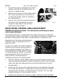
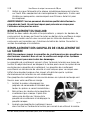
DRIVE SPEED CONTROL CABLE ADJUSTMENT
WARNING! Entanglement Hazard – Use caution when performing the speed
control cable adjustment.
The speed control lever is connected to two cables that work in tandem to
control machine speed and direction. As the speed control lever is moved from
forward to reverse gears, one cable is pulled and one is pushed (Fig. 10).
Depending on if the cable setting towards
forward or reverse, adjustment of the
cables will vary.
To adjust the cables, one cable should be
moved up and the other down equally in
their respective brackets until there is a
positive direction change when the lever
is shifted between F1 and R1. The middle
position between these two settings is
neutral (there is no actual neutral
‘notched’ position on the control panel).
1. With the engine running engage the drive control handle and move the
speed control lever between 1 and R1 to determine which way the cables
need to be adjusted. Release the drive control handle when shifting
between gears.
2. Loosen the jam nuts on each cable (only one or two threads) and move
each cable up and down as required until a positive direction change is
achieved when the lever is shifted between F1 and R1. This may take
multiple attempts to find the exact setting.
3. Tighten the cable jam nuts once the proper setting has been achieved.
Fig. 9
Fig. 10

V1.0 28 in. Gas Snow Thrower 8871626
Visit www.princessauto.com for more information 13
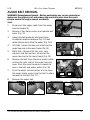
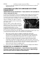
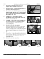
AUGUR BELT REMOVAL
WARNING! Entanglement Hazard – Before performing any service procedures,
make sure the engine is off and remove the spark plug wire from the spark
plug to ensure the engine cannot accidently
start.
1. Disconnect the upper cable from the auger
control handle (C).
2. Remove 2 hex head screws and remove belt
cover (Fig. 12).
3. Loosen the belt guide pin hex head screw
installed on engine crankcase (Fig. 13-1) and
rotate the pin away from the pulley (Fig. 13-2).
4. Left Side - Loosen the hex nuts attaching the
auger housing to the main frame (Fig. 14).
5. Right Side - Remove the hex nuts, lock
washers and flat washers attaching the
auger housing to the main frame (Fig. 15).
6. Remove the belt from the drive pulley while
pulling the right side of the auger housing
away from the main frame just enough to
access the belt and auger pulley (Fig. 16).
7. Push the auger tension pulley arm to move
the auger brake, away from the belt to allow
removal of the belt (Fig. 17).
8. Remove the auger belt.
Fig. 11
Fig. 12
Fig. 13
13-1
13-2
Fig. 14
Fig. 15
Fig. 16
Fig. 17

8871626 28 in. Gas Snow Thrower V1.0
14 For technical questions call 1-800-665-8685
AUGER BELT INSTALLATION
WARNING! Entanglement Hazard – Before performing any service procedures,
make sure the engine is off and remove the spark plug wire from the spark
plug to ensure the engine cannot accidently start.
WARNING! Ensure the belt cover is installed and all safety guards are in place
before the engine is started and at all times when the engine or machine are
operating.
1. Inspect the new belt to ensure it is the correct size and type.
2. Push the auger tension pulley arm to move the auger brake to allow
access for installation of the belt into the auger pulley (Fig. 17).
3. Route the belt to the inside of the tension pulley, auger brake and install
the auger belt onto the drive pulley while pulling the auger housing into
position with the main frame.
4. Install and/or tighten the hex nuts attaching the auger housing to the
main frame. Tighten all fasteners securely, do not over tighten.
5. With the belt installed on both pulleys and tension pulley in position,
move the belt guide pin to within 3/16 to 3/8 in. from the belt seated in the
pulley and tighten the pin in position (Fig. 18).
The belt guide pin helps keep the belt in the pulley when the belt is
disengaged. The pin should not be tight to the
belt. The pin should be loose enough to allow
the belt to spin freely but not allow the belt to
jump off the pulley.
6. Connect the upper cable to the auger
control handle.
7. Install belt cover using 2 hex head screws.
AUGER BELT AND RELATED
COMPONENT INSPECTION
When replacing your snow blower auger belt it is important to determine the
cause of the failure (if applicable) and take corrective action to avoid repeated
failure.
Inspect the belt
• Correct size and type
• Fraying or peeling apart
• Missing pieces
• Cracks and tears
• Burning
• Uneven wear patterns
Fig. 18

V1.0 28 in. Gas Snow Thrower 8871626
Visit www.princessauto.com for more information 15
• General damage • Foreign material on belt, oil, grease,
dirt etc.
Inspect the auger pulleys
• Broken sheave or hub
• Loose or missing mounting bolts
• Bent or "out-of-round" condition
(pulley doesn’t spin true)
• Misaligned pulleys
• Foreign material on pulleys, oil,
grease, dirt, etc.
• Misaligned tension pulley
• Tension pulley loose or damaged
• Tension pulley and arm assembly
operation
• Does the tension arm move freely
both engaged and disengaged
directions without binding?
• Misaligned tension pulley, the
pulley should move parallel to the
belt centered to the belt
• Check return spring operation and
tension
Inspect the auger engagement handle and cable
• Cable and connection damage
• Free movement (from engage to
disengaged positions)
• Binding or improperly routed cable
• Cable pulley(s) damage,
misalignment and binding
• Cable adjustment plate damaged or
improper installation
• Handle damaged or binding at pivot
CLEANING
1. Clean the snowblower surfaces with a damp cloth and mild detergent.
Never allow soap or water inside the working mechanisms.
2. Remove snow and ice buildup before storing or transporting.
LUBRICATION
Inspect and lubricate the tool when required. Only use light oil to lubricate the
tool. Other lubricants may not be suitable and could damage the tool or cause a
malfunction during use.
STORAGE
Never store your snowblower with fuel in the tank or carburetor for extended
periods of time. Consult the engine manual for storage preparations.
Cover the snowblower loosely with a tarp for added protection.

8871626 28 in. Gas Snow Thrower V1.0
16 For technical questions call 1-800-665-8685
DISPOSAL
Recycle a tool damaged beyond repair at the appropriate facility.
Contact your local municipality for a list of disposal facilities or by-laws for
electronic devices, batteries, oil or other toxic liquids.
IMPORTANT! DO NOT pollute the environment by allowing uncontrolled
discharge of waste oil.
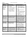
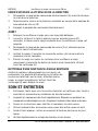
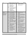
TROUBLESHOOTING
Visit a Princess Auto Ltd. location for a solution if the tool does not function
properly or parts are missing. If unable to do so, have a qualified technician
service the tool.
Problem(s)
Possible Cause(s)
Suggested Solution(s)
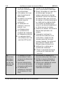
Engine Fails
to Start
(Engine
cranks
over).
1. Engine ignition
switch in OFF
position.
2. Spark plug wire
disconnected.
3. Faulty spark plug.
4. Engine flooded with
fuel.
5. Safety key not
inserted in engine
ignition.
1. Position engine ignition switch
to ON.
2. Connect wire to spark plug.
3. Clean, adjust gap, or replace
spark plug, see Engine
Operator's manual.
4. Discontinue choke or primer
use, clean or replace spark
plug.
5. Insert key fully into the switch.
Engine Fails
to Start
(Engine
cranks
over)
continued.
6. Choke not in start
position.
7. Engine not primed
with fuel.
8. Fuel incorrect, old
or stale, will not
ignite.
9. Blocked or clogged
fuel system or line.
10. Fuel shut-off valve
in OFF position.
6. Move choke to start position,
after engine starts slowly move
to run position as engine speed
and operation stabilizes at the
set rpm. If engine still does not
start move to half choke and
crank engine.
7. Prime engine, see Engine
Operator's manual.
8. Empty and clean fuel tank &
carburetor, refill with fresh,
clean gasoline. (Fuel may

V1.0 28 in. Gas Snow Thrower 8871626
Visit www.princessauto.com for more information 17
become stale after 30 days in
some cases).
9. Clean fuel system or line.
10. Turn fuel shut-off valve to ON
position.
Engine
electric
starter will
not crank
engine
1. Extension cord is
not properly
attached to electric
starter terminal.
2. No power from
power supply,
tripped breaker.
3. Extension cord wire
gauge is too small
or cord is too long.
1. Re-insert extension cord into
electric starter terminal.
2. Check power supply extension
cord is attached to.
3. Use proper rated and length
extension cord, see Engine
Operator's manual.
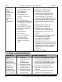
Engine runs
erratic,
stalls or
seems low
on power
1. Choke in ON or
partial ON position
2. Fuel incorrect, old
or stale
3. Blocked or clogged
fuel system or line
4. Carburetor is in
need of cleaning
5. Spark plug wire
loose
6. Faulty spark plug
7. Engine oil over filled
8. Engine oil level low
or empty
1. Move choke lever to run
2. Empty and clean fuel tank &
carburetor, refill with fresh,
clean gasoline. (Note: Fuel may
become stale after 30 days in
some cases)
3. Clean fuel system or line
4. Clean fuel system and
carburetor
5. Connect and tighten spark plug
wire
6. Clean, adjust gap, or replace
spark plug, see Engine
Operator's manual
7. Drain oil to proper level. Oil
should not be above the top 2
threads of lower fill plug.
8. Add oil

8871626 28 in. Gas Snow Thrower V1.0
18 For technical questions call 1-800-665-8685
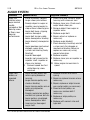
DRIVE SYSTEM
Problem(s)
Possible Cause(s)
Suggested Solution(s)
No forward or
reverse drive
movement
when drive
handle
engaged.
1. Drive belt loose or
damaged.
2. Friction drive wheel is
worn or damaged.
3. Friction drive wheel
wet or slipping.
4. Wheel to axle pins
broken or missing.
1. Check drive belt tension
pulley for damage or
incorrect tension, repair as
necessary. Replace drive
belt.
2. Replace friction drive
wheel.
3. Allow snow blower to dry
and or warm up or adjust
drive cable tension as
necessary.
4. Replace pins attaching
wheels to axle.
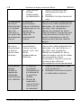
Drive speed
control stuck in
gear or won’t
change gears.
Speed control lever loose
or damaged, not moving
speed control cables.
Check speed control lever
and cables for damage or
loose or missing parts. Repair
or replace parts as needed,
ensure pivot stud spring
tension is correct, adjust
pivot nut spring tension as
needed.
Drive speed
control allows
only 1 direction.
Speed control cables
misadjusted, loose,
damaged or binding.
Check speed control lever and
cables for damage or loose or
missing parts. Repair or
replace parts as needed.
Adjust drive speed control
cables, see Drive Speed
Control Cables Adjustment.
Drive engaged
when drive
control handle
released.
1. Drive control cable
binding, won’t release.
2. Friction drive wheel
return spring broke or
missing.
1. Repair, replace cable as
necessary.
2. Replace spring, adjust
cable as necessary.

V1.0 28 in. Gas Snow Thrower 8871626
Visit www.princessauto.com for more information 19
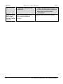
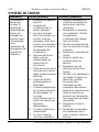
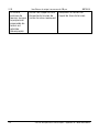
AUGUR SYSTEM
Problem(s)
Possible Cause(s)
Suggested Solution(s)
Auger not
rotating when
auger control
handle
engaged or Not
blowing snow
or Poor snow
blowing
performance.
1. Chute assembly clogged.
2. Auger shear pins broken.
3. Foreign object in auger or
impeller causing auger to
stop without shearing pins.
4. Auger belt loose, slipping,
worn or damaged.
5. Auger belt tension cable
loose, damaged or binding.
6. Auger blade(s) damaged or
bent.
7. Auger gearbox mechanical
damage, auger drive
system not rotating freely
(binding).
8. Impeller damaged.
9. Impeller not connected to
impeller shaft, impeller or
shear pins broken.
10. Forward speed too fast
while blowing snow,
overload.
1. Clean chute and inside of auger
housing with clean-out tool.
2. Replace shear pins. Check each
auger blade shear pin.
3. Remove object from auger or
impeller areas.
4. Replace auger belt.
5. Repair, adjust or replace as
necessary.
6. Replace auger blade(s).
7.
Check bearings, bushings and all
system parts for damage or
mechanical binding. Repair or
replace as necessary using
proper lubrication.
8. Replace impeller.
9.
Replace shear pins or impeller as
necessary.
10. Allow engine to maintain its
speed.
Auger belt
broken, or
repeated
failure.
1. Auger tension pulley arm
return spring broken or
missing.
2. Auger tension pulley arm
stuck or binding.
3. Auger tension pulley arm or
pulley misaligned or
damaged.
4. Foreign material on pulleys
and belt, oil, grease, dirt etc.
5. Auger pulleys misaligned,
loose, damaged or bent.
6. Incorrect or damaged
auger belt.
1. Replace tension arm return
spring.
2. Repair or replace tension arm as
necessary.
3. Repair, replace or align tension
arm and or pulley as necessary.
4. Clean belt and pulleys as
necessary, replace belt if
necessary.
5. Replace or align pulleys as
necessary.
6. Replace with correct size and
type belt.

8871626 28 in. Gas Snow Thrower V1.0
20 For technical questions call 1-800-665-8685
7. Auger belt guide pin not
adjusted.
7. Adjust belt guide pin to within 1/8
to 3/16 in. from pulley. (Guide pin
keeps belt in pulley when
disengaged).
Auger rotating
when auger
control handle
released.
Auger tension pulley arm
return spring broken or
missing.
Replace tension arm return spring.
La page charge ...
La page charge ...
La page charge ...
La page charge ...
La page charge ...
La page charge ...
La page charge ...
La page charge ...
La page charge ...
La page charge ...
La page charge ...
La page charge ...
La page charge ...
La page charge ...
La page charge ...
La page charge ...
La page charge ...
La page charge ...
La page charge ...
La page charge ...
La page charge ...
La page charge ...
La page charge ...
La page charge ...
La page charge ...
La page charge ...
La page charge ...
La page charge ...
La page charge ...
La page charge ...
La page charge ...
La page charge ...
La page charge ...
La page charge ...
La page charge ...
La page charge ...
La page charge ...
La page charge ...
La page charge ...
La page charge ...
-
 1
1
-
 2
2
-
 3
3
-
 4
4
-
 5
5
-
 6
6
-
 7
7
-
 8
8
-
 9
9
-
 10
10
-
 11
11
-
 12
12
-
 13
13
-
 14
14
-
 15
15
-
 16
16
-
 17
17
-
 18
18
-
 19
19
-
 20
20
-
 21
21
-
 22
22
-
 23
23
-
 24
24
-
 25
25
-
 26
26
-
 27
27
-
 28
28
-
 29
29
-
 30
30
-
 31
31
-
 32
32
-
 33
33
-
 34
34
-
 35
35
-
 36
36
-
 37
37
-
 38
38
-
 39
39
-
 40
40
-
 41
41
-
 42
42
-
 43
43
-
 44
44
-
 45
45
-
 46
46
-
 47
47
-
 48
48
-
 49
49
-
 50
50
-
 51
51
-
 52
52
-
 53
53
-
 54
54
-
 55
55
-
 56
56
-
 57
57
-
 58
58
-
 59
59
-
 60
60


Powerfist 8871626 Le manuel du propriétaire
- Catégorie
- Souffleuses à neige
- Taper
- Le manuel du propriétaire
dans d''autres langues
- English: Powerfist 8871626 Owner's manual
Documents connexes
Autres documents
-
Power Fist 8871626 Manuel utilisateur
-
Bercomac 700374-1 Le manuel du propriétaire
-
-
-
Troy-Bilt 31AS6BN2B66 Manuel utilisateur
-
Bolens 31AS32AD565 Le manuel du propriétaire
-
MTD 300 Series Manuel utilisateur
-
Cub Cadet 3x Manuel utilisateur
-
-
 Yardworks 500 Series Manuel utilisateur
