Blackstone 6001 Le manuel du propriétaire
- Taper
- Le manuel du propriétaire

BLACKSTONEPRODUCTS.COM/SUPPORT
ENGLISH
SAFETY ALERT KEY
⚠ DANGER
Indicates a hazardous situation
that, if not avoided, will result in
death or serious injury.
⚠ CAUTION
Indicates a hazardous situation
that, if not avoided, could result
in minor or moderate injury.
⚠ WARNING
Indicates a hazardous situation
that, if not avoided, could result
in death or serious injury.
NOTICE
Indicates information considered
important, but not hazard-
related (e.g. messages related to
property damage).
OWNER’S MANUAL
IMPORTANT:
This instruction manual contains important
information necessary for the proper assembly and safe
use of the appliance.
Read and follow all warnings and instructions before
assembling and using the appliance.
Follow all warnings and instructions when using
the appliance.
Keep this manual for future reference.
Installer/Assembler: Leave these instructions with the consumer.
For the latest version of this manual,
scan this code or visit
BlackstoneProducts.com/support
| CONTACT CUSTOMER SUPPORT BEFORE RETURNING APPLIANCE TO RETAILER.
MODEL: v06
5' X 8' BAR & GRILL
TABLE OF CONTENTS
ASSEMBLY GUIDE . . . . . . . . . . . . . . . . . . . . . . . . . . . . . . . . . . . . . . . . . . . . . . .
USING YOUR BLACKSTONE . . . . . . . . . . . . . . . . . . . . . . . . . . . . . . . . . . . .

ENGLISH
BLACKSTONEPRODUCTS.COM/SUPPORT
OWNER’S MANUAL | ASSEMBLY GUIDE MODEL:
ASSEMBLY GUIDE
{A1} Post 1 (1 piece) {A2} Post 2 (1 piece) {A3} Post 3 (1 piece) {A4} Post 4 (1 piece) {A5} Post 5 (1 piece) {A6} Post 6 (1 piece)
{A7} Post 7 (1 piece) {A8} Post 8 (2 pieces) {A9} Foot base
(5 pieces) {B} Foot base
(5 pieces) {C} Foot base cover
(5 pieces) {D1} Cross beam
1 (1 piece)
{D2} Cross beam
2 (1 piece) {D3} Cross beam
3 (1 piece) {D4} Cross beam
4 (1 piece) {D5} Cross beam
5 (1 piece) {E1} Cross beam
connector 1 (3 pieces) {E2} Cross beam
connector 2 (2 pieces)
{E3} Cross beam
connector 3 (2 piece) {E4} Cross beam
connector 4 (1 piece) {F1} Roof rib 1 (1 piece) {F2} Roof rib 2 (1 piece) {G1} Roof top rib
1 (1 piece) {G2} Roof top rib
2 (1 piece)
{H1} Gutter 1 (1 piece) {H2} Gutter 2 (1 piece) {J1} Top support
1 (1 piece) {J2} Top support
2 (1 piece) {J3} Bottom support
1 (1 piece) {J4} Bottom support
2 (1 piece)
{K1} Support bracket
1 (1 piece) {K2} Support bracket
2 (1 piece) {K3} Support bracket 3
(2 pieces) {L1} Shelf 1 (1 piece) {L2} Shelf 2 (1 piece) {M1} Roof panel
1 (1 piece)
{M2} Roof panel
2 (1 piece) {M3} Roof panel
3 (1 piece) {M4} Roof panel
4 (1 piece) {M5} Roof panel 5
(2 pieces) {N} Bottle
opener (1 piece) {P} Electrical power
cover (1 piece)
PARTS LIST
FRONTFRONT
FRONFRONTT
FFRROONNTT
FFRROONNTT
FRONTFRONT
FRONTFRONT
FFRROONNTT
FRONTFRONT
FRONTFRONT
FFRROONNTT

BLACKSTONEPRODUCTS.COM/SUPPORT
ENGLISH
| OWNER’S MANUALASSEMBLY GUIDEMODEL:
HARDWARE
[AA] M6*20 bolts
(107+5 pieces) [BB]M6*30 bolts
(2 pieces) [CC] M6*35 bolts
(22+4 pieces) [DD] M6*14 Flat
washer (14+2 pieces) [EE] Sealant washer
(12+2 pieces) [FF] M3x10 bolts
(4 pieces)
[GG] M6 nuts
(4 pieces) [HH] M6*16 flat
washer (121+10 pieces)
[JJ] M8×70 Concrete
anchor (20 pieces) [KK] Plastic cap
(12 pieces) [LL] Magnetic hook
(15 pieces)
TOOLS INCLUDED
[Z1] Double end open
wrench (1 piece) [Z2] Angle drill
adapter (1 piece) [Z3]Hex socket driver
10mm×65mm (1 piece) [Z4]Hex drill bit
4mm×50mm (1 piece) [Z5] M3 Screwdriver
(1 piece) Follow all safety
warnings provided
with your tools.
A step-ladder (not included) is required for assembly.
Check the components against the parts list and make sure there are
no missing parts.
Lay pieces on cardboard or a soft mat to help protect the pieces from
scratches.

ENGLISH
BLACKSTONEPRODUCTS.COM/SUPPORT
OWNER’S MANUAL | ASSEMBLY GUIDE
ASSEMBLY INSTRUCTIONS
Find a large, clean area to assemble your appliance.
Remove all packing material before assembling.
⚠ CAUTION
Sharp edges. Wear gloves while assembling.
NOT INCLUDED (OPTIONAL):
Two (2) D batteries
ELECTRIC REQUIREMENTS:
120V 60Hz
MODEL:
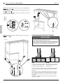
STEP 01 Slide one (1) foot base cover {C} onto one (1) post 8 {A8}.
Use four (4) [AA] bolts and four (4) [HH] flat washers to attach one (1)
foot base {B} to the bottom of post 8 {A8}.
Repeat with the other post 8 {A8}, and posts {A7}, {A5}, and {A2}.
For ease of assembly, it is recommended to have 3 or more people
and allow enough time to completely finish the assembly.
(Assembly can take 6-8 hours.)
DO NOT tighten screws until all the screws and washers are properly
installed.
STEP 02 Pull the electric cord out through the plug on post 5 {A5}.
Use three (3) [KK] plastic caps, three (3) [AA] bolts, and three (3)
[DD] flat washers to attach post 4 {A4} and post 5 {A5}. Note: The
FRONT arrows should face each other.
Repeat with post 6 {A6} to one (1) post 8 {A8}.
Use three (3) [KK] plastic caps, three (3) [AA] bolts, and three (3)
[DD] flat washers to attach post 3 {A3} and one (1) post 8 {A8}.
Repeat with post 1 {A1} and post 2 {A2}.
STEP 03 Use two (2) [AA] bolts and two (2) [HH] flat washers to
attach cross beam 3 {D3} and cross beam 4 {D4}.
STEP 04 Use two (2) [AA] bolts and two (2) [HH] flat washers to
attach cross beam 1 {D1} and cross beam 2 {D2}.
A8
A8
A7
A5
A2
[AA] × 20
[HH] × 20
CB
D3
D4
[AA] × 2
[HH] × 2 D1
D2
[AA] × 2
[HH] × 2
A8
A6
A8
A3
A5
A4
A2
A1
[AA] × 12
[DD] × 12
[KK] × 12

BLACKSTONEPRODUCTS.COM/SUPPORT
ENGLISH
| OWNER’S MANUALASSEMBLY GUIDEMODEL:
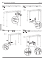
STEP 05 Use two (2) [CC] bolts and two (2) [HH] flat washers to
attach post assembly {A3} to roof rib 2 {F2}.
Repeat with post assembly {A1} and roof rib 1 {F1}.
Use two (2) [CC] bolts and two (2) [HH] flat washers to attach one (1)
cross beam connector 1 {E1} and post assembly {A6} to roof rib 2 {F2}.
Repeat with one (1) cross beam connector 1 {E1}, post assembly {A4}
and roof rib 1 {F1}.
STEP 06 Use four (4) [AA] bolts and four (4) [HH] flat washers to
attach one (1) cross beam connector 2 {E2} to roof rib 2 {F2} and post
assembly {A3}.
Use four (4) [AA] bolts and four (4) [HH] flat washers to attach one (1)
cross beam connector 2 {E2} to roof rib 1 {F1} and post assembly {A1}.
STEP 07 Use two (2) [AA] bolts and two (2) [HH] flat washers to
attach one (1) cross beam connector 1 {E1} to roof rib 1 {F1}.
STEP 08 Use two (2) [BB] bolts, four (4) [HH] flat washers, and two (2)
[GG] nuts to attach cross beam connector 4 {E4} and one (1) cross
beam connector 3 {E3} to roof rib 2 {F2}.
E1
[CC] × 8
[HH] × 8
A3
F2
A6 A4
A1
F1
F1
E1
[AA] × 2
[HH] × 2 F2
[BB] × 2
[HH] × 4
[GG] × 2
E3
E4
[GG]
[BB]
E2
F2
A3 A1
F1
[AA] × 8
[HH] × 8

ENGLISH
BLACKSTONEPRODUCTS.COM/SUPPORT
OWNER’S MANUAL | ASSEMBLY GUIDE MODEL:
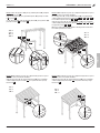
STEP 09 Note: DO NOT tighten the bolts completely until all the bolts
and washers are properly installed.
Use four (4) [AA] bolts and four (4) [HH] flat washers to attach
one (1) support bracket 3 {K3} to post assembly {A3} and roof rib
assembly {F2}.
Use four (4) [AA] bolts and four (4) [HH] flat washers to attach
one (1) support bracket 3 {K3} to post assembly {A1} and roof rib
assembly {F1}.
STEP 10 Use two (2) [AA] bolts and two (2) [HH] flat washers to
attach cross beam {D1} to one (1) cross beam connector 1 {E1}.
Note: the FRONT labels should face forward.
Use two (2) [AA] bolts and two (2) [HH] flat washers to attach cross
beam {D2} to one (1) cross beam connector 3 {E3}.
STEP 11 Use two (2) [AA] bolts and two (2) [HH] flat washers to
attach cross beam {D4} to one (1) cross beam connector 1 {E1}.
Use two (2) [AA] bolts and two (2) [HH] flat washers to attach cross
beam {D3} to one (1) cross beam connector 1 {E1}.
STEP 12 Note: DO NOT tighten the bolts completely until all the bolts
and washers are properly installed.
Use four (4) [AA] bolts and four (4) [HH] flat washers to attach
support bracket 1 {K1} to post assembly {A4} and cross beam {D3}.
Use four (4) [AA] bolts and four (4) [HH] flat washers to attach
support bracket 2 {K2} to post assembly {A6} and cross beam {D4}.
F2 F1
A3 A1
[AA] × 8
[HH] × 8
K3
E1
A6
E1
A4
D4
D3
[AA] × 4
[HH] × 4
K1 K2
D4
D3
A4
A6
[AA] × 8
[HH] × 8
D1
A1
A3
D2
E1
E3
[AA] × 4
[HH] × 4

BLACKSTONEPRODUCTS.COM/SUPPORT
ENGLISH
| OWNER’S MANUALASSEMBLY GUIDEMODEL:
STEP 13 Use two (2) [AA] bolts and two (2) [HH] flat washers to
attach roof top rib 1 {G1} to roof top rib 2 {G2}.
Note: the ARROWS should face the same direction.
STEP 15 Use two (2) [AA] bolts and two (2) [HH] flat washers to
attach roof top rib 1 {G1} to roof rib {F1}.
Use two (2) [AA] bolts and two (2) [HH] flat washers to attach roof
top rib 2 {G2} to roof rib {F2}.
STEP 14 Use two (2) [AA] bolts and two (2) [HH] flat washers to
attach top support 1 {J1} to top support 2 {J2}.
STEP 16 Note: DO NOT tighten the bolts completely until all the bolts
and washers are properly installed.
Use three (3) [AA] bolts and three (3) [HH] flat washers to attach top
support 1 {J1} to post assembly {A1}.
Use three (3) [AA] bolts and three (3) [HH] flat washers to attach top
support 2 {J2} to post assembly {A3}.
G1
G2
F2
F1
[AA] × 4
[HH] × 4
A1
A3
[AA] × 6
[HH] × 6
J1
J2
G1
G2
[AA] × 2
[HH] × 2
J1
J2
[AA] × 2
[HH] × 2

ENGLISH
BLACKSTONEPRODUCTS.COM/SUPPORT
OWNER’S MANUAL | ASSEMBLY GUIDE MODEL:
STEP 18 Use four (4) [AA] bolts and four (4) [GG] flat washers
to attach bottom support 1 {J3} to post assembly {A2} and post
assembly {A7}.
STEP 19 Use four (4) [AA] bolts and four (4) [HH] flat washers to
attach bottom support 2 {J4} to posts {A5} and {A2}.
STEP 20 Use two (2) [AA] bolts and two (2) [HH] flat washers to
attach shelf 2 {L2} to post {A1}.
Use three (3) [AA] bolts and three (3) [HH] flat washers to attach
shelf 2 {L2} to post {A7}.
STEP 17 Use four (4) [AA] bolts and four (4) [HH] flat washers
to attach cross beam 5 {D5} to post assembly {A6} and post
assembly {A3}.
J3
A2
A7
[AA] × 4
[HH] × 4
L2
A1
A7
[AA] × 5
[HH] × 5
J4 A2
A5
[AA] × 4
[HH] × 4
A3
A6 D5
[AA] × 4
[HH] × 4

BLACKSTONEPRODUCTS.COM/SUPPORT
ENGLISH
| OWNER’S MANUALASSEMBLY GUIDEMODEL:
STEP 21 Use two (2) [AA] bolts and two (2) [HH] flat washers to
attach shelf 1 {L1} to post {A4}.
Use two (2) [AA] bolts and two (2) [HH] flat washers to attach shelf 1
{L1} to post {A1}.
Use two (2) [CC] bolts, four (4) [HH] flat washers, and two (2) [GG]
nuts to attach shelf 1 {L1} to shelf 2 {L2}.
STEP 22 Note: DO NOT tighten the bolts completely until all the bolts
and washers are properly installed.
Use six (6) [CC] bolts, six (6) [HH] flat washers, and six (6) [EE]
sealant washers to attach roof panels {M1}, {M2}, {M3}, {M4}, and {M5}
to roof top ribs {G1} and {G2}.
Use two (2) [CC] bolts, two (2) [HH] flat washers, and two (2) [EE]
sealant washers to attach roof panels {M1}, {M2}, {M3}, {M4}, and {M5}
to cross beams {D3} and {D4}.
Note: If the holes don't align during the assembly, pull the cross-
beams outward to align the holes.
STEP 23 Note: DO NOT tighten the bolts completely until all the bolts
and washers are properly installed.
Use two (2) [CC] bolts, two (2) [HH] flat washers, and two (2) [EE]
sealant washers to attach gutter 2 {H2} to the roof panels and cross
beam {D4}.
STEP 24 Note: DO NOT tighten the bolts completely until all the bolts
and washers are properly installed.
Use two (2) [CC] bolts, two (2) [HH] flat washers, and two (2) [EE]
sealant washers to attach gutter 1 {H1} to the roof panels and cross
beam {D3}.
L2
A1
A4 L1
[AA][AA]
[AA] × 4
[CC] × 2
[HH] × 8
[GG] × 2
[GG]
[AA]
[CC]
[GG]
[CC]
[AA]
[CC] × 2
[EE] × 2
[HH] × 2
D4
H2
[EE]
[HH]
[CC] × 2
[EE] × 2
[HH] × 2
D3
H1
[EE]
[HH]
[EE]
[HH]
[EE]
[HH]
M1
M2
M3
M4
M5
D3
D4
[CC] × 8
[EE] × 8
[HH] × 8

ENGLISH
BLACKSTONEPRODUCTS.COM/SUPPORT
OWNER’S MANUAL | ASSEMBLY GUIDE MODEL:
STEP 25 Use four (4) [FF] bolts to attach the electrical power cover
{P} to post {A4}.
Use two (2) [AA] bolts and two [DD] flat washers to attach the bottle
opener {N} to post {A1}.
Stick the magnetic hooks [LL] to the front cross beams and roof ribs.
(5 per side is recommended.)
STEP 26 Use four (4) [JJ] expansion bolts to anchor each post
foot base {B}. OUTDOOR STRUCTURE ANCHORING GUIDE
⚠ WARNING
If your BLACKSTONE BAR & GRILL is not properly anchored,
damage could occur.
It is highly recommended for maximum safety that you mount
and secure to wood or concrete footers. This is far better and
safer than using ground stakes.
If digging for foundation, please double check for possibility of any
underground utilities such as gas, telephone, cable or sprinkler lines.
Refer to your local building and city codes, ordinances, neigh-
borhood covenants, or height restrictions regarding this type of
structure for guidance on acceptable installation requirements.
Consider consulting a licensed contractor for assistance in the
anchoring of this product.
WOOD
Anchors should be drilled into
joists or reinforced blocking (not
only deck boards).
CONCRETE
Use a " drill bit (not
included) to pre-drill holes for
concrete anchors.
[JJ] × 20
N
P
[LL]
N
[AA][DD]
P
[FF]
[
AA
] × 2
[DD] × 2
[FF] × 4
[LL] × 15

BLACKSTONEPRODUCTS.COM/SUPPORT
ENGLISH
| OWNER’S MANUALUSING YOUR BLACKSTONE
Register your appliance at
BlackstoneProducts.com/register
The North Atlantic Imports LLC 1-Year Warranty covers replacement
parts up to one year after the date of purchase.
TO ENABLE THIS WARRANTY, YOU WILL NEED TO PROVIDE:
Your appliance’s Serial Number
The Serial Number can be found on your appliance’s
Manufacturer Label.
(The Manufacturer Label is a large silver sticker found on the body of your (The Manufacturer Label is a large silver sticker found on the body of your
appliance.)appliance.)
WARRANTY OVERVIEW
North Atlantic Imports, the manufacturer, will warranty for one year
from purchase all parts, workmanship, and finishes. It will be the
manufacturer’s option as to whether to repair or replace any of the
above items. All warranties are limited to the original purchaser
only. This warranty does not cover any liability on the part of North
Atlantic Imports, its agents or employees, for any indirect or conse-
quential damages for breach of warranty. The purchaser must follow
the manufacturer’s usage instructions.
Under no circumstances is the manufacturer responsible for
damages from the failure to operate the cooking station properly. It is
the responsibility of the purchaser to establish the warranty period
by verifying the original purchase date with original sales receipt.
DETAILED EXPLANATION OF THE WARRANTY
North Atlantic Imports LLC warrants to the owner that the product
covered by this agreement is free from defects in material and work-
manship under normal use and service for which it was intended if,
but only if, it has been operated in accordance with North Atlantic
Imports LLC instructions exclusively for domestic use, and not for
private or public club, institutional or commercial purposes.
North Atlantic Imports LLC’s obligation under this warranty is limited
to replacing or repairing, free of charge, any part or parts that
may prove, to the satisfaction of North Atlantic Imports LLC, to be
defective under normal home use and service within the following
stated periods of time from the date of purchase; for one year from
purchase, all parts, finish, and workmanship. Should any failure
to conform to this warranty become apparent during applicable
warranty periods stated above, the original purchaser must notify
North Atlantic Imports LLC of breach of warranty within the appli-
cable warranty period.
North Atlantic Imports LLC shall upon notice and compliance by the
original purchaser with such instructions, correct such nonconfor-
mity by repair or replacement of the defective part or parts.
Correction in the manner provided above shall constitute a fulfill-
ment of all obligations of North Atlantic Imports LLC with respect to
the quality of the product.
North Atlantic Imports LLC does not warrant this equipment to meet
the requirement of any safety code of any state, municipality or other
jurisdiction, and the original purchaser assumes all risk and liability
whatsoever resulting from the use thereof, whether used in accor-
dance with North Atlantic Imports LLC instructions or otherwise.
This warranty does not cover and is intended to exclude any liability
on the part of North Atlantic its agents, servants or employees
whether under this warranty or implied by law for any indirect or
consequential damages for breach on any warranty. The purchaser
must establish all applicable warranty periods pursuant to this
warranty by verifying the original purchase date by producing the
dated sales receipt. This warranty shall not apply to this product or
any other part thereof which has been subject to accident, negli-
gence, alteration, abuse, or misuse or which has been repaired or
altered without North Atlantic written consent, outside of North
Atlantic Imports LLC factory. The full manufacturer warranty is
not valid for griddles purchased from unlicensed, third-party
resellers, purchased at a discount due to missing or damaged
parts, or purchased as a floor model; at the discretion of North
Atlantic Imports.
North Atlantic Imports LLC makes no warranty whatsoever in respect
to accessories or parts not supplied with it. This warranty shall
apply only within the boundaries of the United States of America and
Canada. This warranty gives the original purchaser specific rights,
and the original purchaser may also have other rights, which vary
from state to state.
������������������������������������������
��������������������������
���������������������������������
����������������������������������������
��������������������������������������
����������������������������������
���������������������������������������
���������������������������
������������������������������������
��������������������������������������
����������������������������������������
����������������������������������������
��������������������������
������������������������������������������
�����������������������������
����������������������������������
�����������������������������������������
����������������������������������������
������������������������������������������
����������������������������
����������������������������
����������������������������������������������������
�������������������������������������������������
��������������������������������
���������������������������������������
���������������������������������������������������
����������������������������������������������������
������������������������������������������������������
��������������������������������
��������������������������������������������
��������������������������������������������������
�������������������������������������������������
������������������������������������������������������
��������
����������������������������������������������������
����������������
����������������
����������������
����������������
�����������������������������������
����������������
������������������������
��������������������������������
��������������������������������
������������
������������������������������������������
��������������������������
���������������������������������
����������������������������������������
��������������������������������������
����������������������������������
���������������������������������������
���������������������������
������������������������������������
��������������������������������������
����������������������������������������
����������������������������������������
��������������������������
������������������������������������������
�����������������������������
����������������������������������
�����������������������������������������
����������������������������������������
������������������������������������������
����������������������������
����������������������������
����������������������������������������������������
�������������������������������������������������
��������������������������������
���������������������������������������
���������������������������������������������������
����������������������������������������������������
������������������������������������������������������
��������������������������������
��������������������������������������������
��������������������������������������������������
�������������������������������������������������
������������������������������������������������������
��������
����������������������������������������������������
��������
��������
��������
��������
��������
����������������
����������������
����������������
����������������
�����������������������������������
����������������
������������������������
��������������������������������
��������������������������������
������������
FREE
MOBILEFRIENDLY
COOKBOOK
when you register
BLACKSTONE BACKYARD BAR & GRILL
LIMITED WARRANTY
Blackstone Products warrants this Backyard Bar and Grill against
defects in materials and workmanship for a period of one (1) year
from the original date of purchase. To the extent any such defects
occur, Blackstone Products will send the appropriate replacement
part(s) at no charge.
This warranty does not cover:
•
Inspection costs or labor for replacement of any defective part(s);
•
Incidental or consequential damages;
•
Cosmetic defects which DO NOT aect performance or integrity;
•
Normal wear and tear;
•
Damage due to vandalism; acts of nature, including but not limited
to wind, storms, hail, floods;
•
Improper assembly, installation, or use;
•
Discoloration or fading of the finish as a result of exposure to chem-
icals, spills, pool or salt water
•
Corrosion/ rust.
Your Backyard Bar and Grill has been designed for safety and quality.
Any modifications made to the original product could compromise
its structural integrity or function, and could lead to product failure
or personal injury. As such, modifying this product voids any and all
warranties.
This product is warranted for RESIDENTIAL USE ONLY, and is not for
commercial, contract or other non-residential purposes. Blackstone
Products disclaims all other representations and warranties of any
kind, express or implied.
The warranty applies to the original purchaser and is non-trans-
ferable. It does not apply to purchases of display models, or when
the product is sold on clearance or “as is”. To activate your warranty,
register your product at www.BlackstoneProducts.com/register.
North Atlantic Imports LLC makes no warranty whatsoever in respect
to accessories or parts not supplied with it. This warranty shall
apply only within the boundaries of the United States of America and
Canada. This warranty gives the original purchaser specific rights,
and the original purchaser may also have other rights, which vary
from state to state.
MODEL:
Enjoy using your BLACKSTONE BAR & GRILL!
USING YOUR BLACKSTONE BAR & GRILL
The BLACKSTONE BAR & GRILL is intended for privacy, decorative
and ornamental use only.
Product is NOT INTENDED for the following:
• A safety barrier to prevent unsupervised access to pools, hot tubs,
spas or ponds.
• As load bearing support for a building, structure, heavy objects
or swings.
• Used in structures that trap wind, rain or snow that would create
extra load on the product.
⚠ CAUTION
DO NOT climb or walk on roof for any reason.
SNOW LOAD CAPACITY
12 lbs/ ft = 480 lbs. of total snow load
Accumulated snow must be removed from roof.
WIND RATING
Beufort scale 8 – Gale force winds (39-46 MPH)
The BLACKSTONE BAR & GRILL should not be used in inclement
weather and high winds.
USING YOUR BLACKSTONE

ENGLISH
BLACKSTONEPRODUCTS.COM/SUPPORT
This product may be covered by one or more issued U.S. and/or
international patents and may include patent applications pending.
For more information, please visit: BlackstoneProducts.com/patents
DISTRIBUTED BY NORTH ATLANTIC IMPORTS, LLC W N LOGAN, UT USA | BLACKSTONE IS A REGISTERED TRADEMARK OF NORTH ATLANTIC IMPORTS, LLC
© NORTH ATLANTIC IMPORTS. ALL RIGHTS RESERVED.

BLACKSTONEPRODUCTS.COM/SUPPORT
FRANÇAIS
CLÉ D’ALERTE DE SÉCURITÉ
⚠ AVERTISSEMENT
Indique une situation dangereuse qui,
si elle n’est pas évitée, peut entraîner
la mort ou des blessures graves.
AVIS
Indique des informations considé-
rées comme importantes, mais non
liées à un danger (par exemple, des
messages liés à des dommages
matériels).
MANUEL DU PROPRIÉTAIRE
⚠ DANGER
Indique une situation dangereuse qui,
si elle n’est pas évitée, entraînera la
mort ou des blessures graves.
⚠ ATTENTION
Indique une situation dangereuse
qui, si elle n’est pas évitée, pourrait
entraîner des blessures mineures
ou modérées.
IMPORTANT:
Ce manuel d’instructions contient des informations impor-
tantes nécessaires au montage correct et à l’utilisation en
toute sécurité de l’appareil.
Lisez et suivez tous les avertissements et instructions
avant d’assembler et d’utiliser l’appareil.
Suivez tous les avertissements et instructions lors de
l’utilisation de l’appareil.
Conservez ce manuel pour référence ultérieure.
Installateur/Assembleur : Laisser ces instructions au consommateur.
Pour obtenir la dernière version de ce manuel,
scannez ce code ou visitez
BlackstoneProducts.com/support
| CONTACTEZ LE SERVICE CLIENT AVANT DE RETOURNER L’APPAREIL AU REVENDEUR.
BAR ET GRILL 5' X 8'
MODÈLE: v06
TABLE DES MATIÈRES
GUIDE D’ASSEMBLAGE . . . . . . . . . . . . . . . . . . . . . . . . . . . . . . . . . . . . . . . . . . .
UTILISATION DE VOTRE BLACKSTONE . . . . . . . . . . . . . . . . . . . . . . . . .

BLACKSTONEPRODUCTS.COM/SUPPORT
FRANÇAIS
MANUEL DU PROPRIÉTAIRE | GUIDE D’ASSEMBLAGE MODÈLE:
GUIDE D’ASSEMBLAGE
LISTE DES PIÈCES
{A1} Poteau 1 (1 pièce) {A2} Poteau 2 (1 pièce) {A3} Poteau 3 (1 pièce) {A4} Poteau 4 (1 pièce) {A5} Poteau 5 (1 pièce) {A6} Poteau 6 (1 pièce)
{A7} Poteau 7 (1 pièce) {A8} Poteau 8 (2 pièces) {A9} Base de pied
(5 pièces) {B} Base de pied
(5 pièces)
{
C
} Couvre-pied (5 pièces)
{D1} Traverse 1 (1 pièce)
{D2} Traverse 2 (1 pièce) {D3} Traverse 3 (1 pièce) {D4} Traverse 4 (1 pièce) {D5} Traverse 5 (1 pièce) {E1} Connecteur de
traverse 1 (3 pièces) {E2} Connecteur de
traverse 2 (2 pièces)
{E3} Connecteur de
traverse 3 (2 pièces) {E4} Connecteur de
traverse 4 (1 pièce) {F1} Nervure de toit
1 (1 pièce) {F2} Nervure de toit
2 (1 pièce) {G1} Nervure de toit
1 (1 pièce) {G2} Nervure de toit
2 (1 pièce)
{H1} Gouttière 1 (1 pièce) {H2} Gouttière 2 (1 pièce) {J1} Support supérieur
1 (1 pièce) {J2} Support supérieur
2 (1 pièce) {J3} Support inférieur
1 (1 pièce) {J4} Support inférieur
2 (1 pièce)
{K1} Équerre de support
1 (1 pièce) {K2} Équerre de support
2 (1 pièce) {K3} Équerre de support 3
(2 pièces) {L1} Étagère 1 (1 pièce) {L2} Étagère 2 (1 pièce) {M1} Panneau de toit
1 (1 pièce)
{M2} Panneau de toit
2 (1 pièce) {M3} Panneau de toit
3 (1 pièce) {M4} Panneau de toit
4 (1 pièce) {M5} Panneau de toit 5
(2 pièces) {N} Ouvre-
bouteille (1 pièce) {P} Couvercle d'alimenta-
tion électrique (1 pièce)
FRONTFRONT
FRONFRONTT
FFRROONNTT
FFRROONNTT
FRONTFRONT
FRONTFRONT
FFRROONNTT
FRONTFRONT
FRONTFRONT
FFRROONNTT

BLACKSTONEPRODUCTS.COM/SUPPORT
FRANÇAIS
| MANUEL DU PROPRIÉTAIREGUIDE D’ASSEMBLAGEMODÈLE:
Un escabeau (non inclus) est requis pour le montage.
Vérifiez les composants par rapport à la liste des pièces et assurez-vous qu’il ne
manque aucune pièce.
Étendez les pièces sur du carton ou un tapis doux pour aider à protéger les
pièces des égratignures.
MATÉRIEL
[AA] Boulons M6*20
(107+5 pièces) [BB] Boulons M6*30
(2 pièces) [CC] Boulons M6*35
(22+4 pièces) [DD] M6*14 Rondelle plate
(14+2 pièces) [EE] Rondelle d'étanchéité
(12+2 pièces) [FF] Boulons M3x10
(4 pièces)
[GG] Écrous M6 (4 pièces) [HH] Rondelle plate M6*16
(121+10 pièces) [JJ] Ancrage à béton
M8×70 (20 pièces) [KK] Bouchon en plas-
tique (12 pièces) [LL] Crochet magnétique
(15 pièces)
OUTILS INCLUS
[Z1] Clé à fourche
double (1 pièce) [Z2] Adaptateur pour
perceuse d’angle (1 pièce) [Z3] Tournevis à douille
hexagonale 10 mm ×
65 mm (1 pièce)
[Z4]Foret hexagonal 4mm
× 50mm (1 pièce) [Z5] Tournevis
M3 (1 pièce) Suivez tous les avertisse-
ments de sécurité fournis
avec vos outils.

BLACKSTONEPRODUCTS.COM/SUPPORT
FRANÇAIS
MANUEL DU PROPRIÉTAIRE | GUIDE D’ASSEMBLAGE
EXIGENCES ÉLECTRIQUES:
120V 60Hz
INSTRUCTIONS DE MONTAGE
Trouvez une grande surface propre pour assembler votre appareil.
Retirez tous les matériaux d’emballage avant l’assemblage.
⚠ ATTENTION
Bouts pointus. Portez des gants lors de l’assemblage.
NON INCLUS (EN OPTION):
Deux (2) piles D
MODÈLE:
Pour faciliter l’assemblage, il est recommandé d’avoir 3 personnes ou plus et de
prévoir suisamment de temps pour terminer complètement l’assemblage.
(L’assemblage peut prendre 6 à 8 heures.)
NE PAS serrer les vis tant que toutes les vis et rondelles ne sont pas correcte-
ment installées.
ÉTAPE 01 Faites glisser un (1) couvercle de base de pied {C} sur un (1)
poteau 8 {A8}.
Utilisez quatre (4) boulons [AA] et quatre (4) rondelles plates [HH] pour fixer
une (1) base de pied {B} au bas du poteau 8 {A8}.
Répétez avec l’autre poteau 8 {A8} et les poteaux {A7}, {A5} et {A2}.
ÉTAPE 02 Tirez le cordon électrique à travers la prise sur la borne 5 {A5}.
Utilisez trois (3) capuchons en plastique [KK], trois (3) boulons [AA] et trois (3)
rondelles plates [DD] pour fixer le poteau 4 {A4} et le poteau 5 {A5}. Remarque :
Les flèches FRONT doivent se faire face.
Répétez avec le poteau 6 {A6} à un (1) poteau 8 {A8}.
Utilisez trois (3) capuchons en plastique [KK], trois (3) boulons [AA] et trois (3)
rondelles plates [DD] pour fixer le poteau 3 {A3} et un (1) poteau 8 {A8}.
Répétez avec le poteau 1 {A1} et le poteau 2 {A2}.
ÉTAPE 03 Utilisez deux (2) boulons [AA] et deux (2) rondelles plates [HH] pour
fixer la traverse 3 {D3} et la traverse 4 {D4}.
ÉTAPE 04 Utilisez deux (2) boulons [AA] et deux (2) rondelles plates [HH] pour
fixer la traverse 1 {D1} et la traverse 2 {D2}.
A8
A8
A7
A5
A2
[AA] × 20
[HH] × 20
CB
D3
D4
[AA] × 2
[HH] × 2 D1
D2
[AA] × 2
[HH] × 2
A8
A6
A8
A3
A5
A4
A2
A1
[AA] × 12
[DD] × 12
[KK] × 12

BLACKSTONEPRODUCTS.COM/SUPPORT
FRANÇAIS
| MANUEL DU PROPRIÉTAIREGUIDE D’ASSEMBLAGEMODÈLE:
ÉTAPE 05 Utilisez deux (2) boulons [CC] et deux (2) rondelles plates [HH] pour
fixer l’ensemble de montant {A3} à la nervure de toit 2 {F2}.
Répétez avec l’ensemble de montant {A1} et la nervure de toit 1 {F1}.
Utilisez deux (2) boulons [CC] et deux (2) rondelles plates [HH] pour fixer un (1)
connecteur de poutre transversale 1 {E1} et l’assemblage de poteau {A6} à la
nervure de toit 2 {F2}.
Répétez l’opération avec un (1) connecteur de poutre transversale 1 {E1}, l’as-
semblage de poteau {A4} et la nervure de toit 1 {F1}.
ÉTAPE 06
Utilisez quatre (4) boulons [AA] et quatre (4) rondelles plates [HH]
pour fixer un (1) connecteur de poutre transversale 2 {E2} à la nervure de toit 2
{F2} et à l’assemblage de montant {A3}.
Utilisez quatre (4) boulons [AA] et quatre (4) rondelles plates [HH] pour fixer
un (1) connecteur de poutre transversale 2 {E2} à la nervure de toit 1 {F1} et à
l’ensemble de montant {A1}.
ÉTAPE 07 Utilisez deux (2) boulons [AA] et deux (2) rondelles plates [HH] pour
fixer un (1) connecteur de traverse 1 {E1} à la nervure de toit 1 {F1}.
ÉTAPE 08
Utilisez deux (2) boulons [BB], quatre (4) rondelles plates [HH] et deux
(2) écrous [GG] pour fixer le connecteur de traverse 4 {E4} et un (1) connecteur
de traverse 3 {E3} à la nervure de toit 2 {F2}.
E1
[CC] × 8
[HH] × 8
A3
F2
A6 A4
A1
F1
F1
E1
[AA] × 2
[HH] × 2
F2
[BB] × 2
[HH] × 4
[GG] × 2
E3
E4
[GG]
[BB]
E2
F2
A3 A1
F1
[AA] × 8
[HH] × 8

BLACKSTONEPRODUCTS.COM/SUPPORT
FRANÇAIS
MANUEL DU PROPRIÉTAIRE | GUIDE D’ASSEMBLAGE MODÈLE:
ÉTAPE 09
Remarque: Ne serrez pas complètement les boulons tant que tous les
boulons et rondelles ne sont pas correctement installés.
Utilisez quatre (4) boulons [AA] et quatre (4) rondelles plates [HH] pour fixer un
(1) support de support 3 {K3} à l’assemblage de poteau {A3} et à l’assemblage
de nervure de toit {F2}.
Utilisez quatre (4) boulons [AA] et quatre (4) rondelles plates [HH] pour fixer un
(1) support de support 3 {K3} à l’assemblage de poteau {A1} et à l’assemblage
de nervure de toit {F1}.
ÉTAPE 10 Utilisez deux (2) boulons [AA] et deux (2) rondelles plates [HH] pour
fixer la traverse {D1} à un (1) connecteur de traverse 1 {E1}.
Remarque: les étiquettes FRONT doivent être orientées vers l’avant.
Utilisez deux (2) boulons [AA] et deux (2) rondelles plates [HH] pour fixer la
traverse {D2} à un (1) connecteur de traverse 3 {E3}.
ÉTAPE 11 Utilisez deux (2) boulons [AA] et deux (2) rondelles plates [HH] pour
fixer la traverse {D4} à un (1) connecteur de traverse 1 {E1}.
Utilisez deux (2) boulons [AA] et deux (2) rondelles plates [HH] pour fixer la
traverse {D3} à un (1) connecteur de traverse 1 {E1}.
ÉTAPE 12 Remarque: Ne serrez pas complètement les boulons tant que tous les
boulons et rondelles ne sont pas correctement installés.
Utilisez quatre (4) boulons [AA] et quatre (4) rondelles plates [HH] pour fixer le
support 1 {K1} à l’ensemble de poteau {A4} et à la traverse {D3}.
Utilisez quatre (4) boulons [AA] et quatre (4) rondelles plates [HH] pour fixer le
support 2 {K2} à l’ensemble de poteau {A6} et à la traverse {D4}.
F2 F1
A3 A1
[AA] × 8
[HH] × 8
K3
E1
A6
E1
A4
D4
D3
[AA] × 4
[HH] × 4
K1 K2
D4
D3
A4
A6
[AA] × 8
[HH] × 8
D1
A1
A3
D2
E1
E3
[AA] × 4
[HH] × 4

BLACKSTONEPRODUCTS.COM/SUPPORT
FRANÇAIS
| MANUEL DU PROPRIÉTAIREGUIDE D’ASSEMBLAGEMODÈLE:
ÉTAPE 13 Utilisez deux (2) boulons [AA] et deux (2) rondelles plates [HH] pour
fixer la nervure supérieure du toit 1 {G1} à la nervure supérieure du toit 2 {G2}.
Remarque: les FLECHES doivent être orientées dans la même direction.
ÉTAPE 15 Utilisez deux (2) boulons [AA] et deux (2) rondelles plates [HH] pour
fixer la nervure supérieure du toit 1 {G1} à la nervure du toit {F1}.
Utilisez deux (2) boulons [AA] et deux (2) rondelles plates [HH] pour fixer la
nervure supérieure du toit 2 {G2} à la nervure du toit {F2}.
ÉTAPE 14 Utilisez deux (2) boulons [AA] et deux (2) rondelles plates [HH] pour
fixer le support supérieur 1 {J1} au support supérieur 2 {J2}.
ÉTAPE 16 Remarque: Ne serrez pas complètement les boulons tant que tous les
boulons et rondelles ne sont pas correctement installés.
Utilisez trois (3) boulons [AA] et trois (3) rondelles plates [HH] pour fixer le
support supérieur 1 {J1} à l’ensemble de poteau {A1}.
Utilisez trois (3) boulons [AA] et trois (3) rondelles plates [HH] pour fixer le
support supérieur 2 {J2} à l’ensemble de poteau {A3}.
G1
G2
F2
F1
[AA] × 4
[HH] × 4
A1
A3
[AA] × 6
[HH] × 6
J1
J2
G1
G2
[AA] × 2
[HH] × 2
J1
J2
[AA] × 2
[HH] × 2

BLACKSTONEPRODUCTS.COM/SUPPORT
FRANÇAIS
MANUEL DU PROPRIÉTAIRE | GUIDE D’ASSEMBLAGE MODÈLE:
ÉTAPE 18 Utilisez quatre (4) boulons [AA] et quatre (4) rondelles plates [GG]
pour fixer le support inférieur 1 {J3} à l’ensemble de poteau {A2} et à l’ensemble
de poteau {A7}.
ÉTAPE 19 Utilisez quatre (4) boulons [AA] et quatre (4) rondelles plates [HH]
pour fixer le support inférieur 2 {J4} aux montants {A5} et {A2}.
ÉTAPE 20 Utilisez deux (2) boulons [AA] et deux (2) rondelles plates [HH] pour
fixer la tablette 2 {L2} au montant {A1}.
Utilisez trois (3) boulons [AA] et trois (3) rondelles plates [HH] pour fixer la
tablette 2 {L2} au montant {A7}.
ÉTAPE 17 Utilisez quatre (4) boulons [AA] et quatre (4) rondelles plates [HH]
pour fixer la traverse 5 {D5} à l’ensemble de poteau {A6} et à l’ensemble de
poteau {A3}.
J3
A2
A7
[AA] × 4
[HH] × 4
L2
A1
A7
[AA] × 5
[HH] × 5
J4 A2
A5
[AA] × 4
[HH] × 4
A3
A6 D5
[AA] × 4
[HH] × 4
La page est en cours de chargement...
La page est en cours de chargement...
La page est en cours de chargement...
La page est en cours de chargement...
La page est en cours de chargement...
La page est en cours de chargement...
La page est en cours de chargement...
La page est en cours de chargement...
La page est en cours de chargement...
La page est en cours de chargement...
La page est en cours de chargement...
La page est en cours de chargement...
La page est en cours de chargement...
La page est en cours de chargement...
La page est en cours de chargement...
La page est en cours de chargement...
-
 1
1
-
 2
2
-
 3
3
-
 4
4
-
 5
5
-
 6
6
-
 7
7
-
 8
8
-
 9
9
-
 10
10
-
 11
11
-
 12
12
-
 13
13
-
 14
14
-
 15
15
-
 16
16
-
 17
17
-
 18
18
-
 19
19
-
 20
20
-
 21
21
-
 22
22
-
 23
23
-
 24
24
-
 25
25
-
 26
26
-
 27
27
-
 28
28
-
 29
29
-
 30
30
-
 31
31
-
 32
32
-
 33
33
-
 34
34
-
 35
35
-
 36
36


Blackstone 6001 Le manuel du propriétaire
- Taper
- Le manuel du propriétaire
dans d''autres langues
Documents connexes
-
Blackstone 2171 v01 Le manuel du propriétaire
-
 Blackstone 1948 Pro Series Prep/Serve and Store Cart Le manuel du propriétaire
-
Blackstone 6038 36 Inch Griddle Drop-In Le manuel du propriétaire
-
 Blackstone 1863 Le manuel du propriétaire
-
Blackstone 8003 Le manuel du propriétaire
-
 Blackstone 1868 Le manuel du propriétaire
-
 Blackstone 1856 Le manuel du propriétaire
-
 Blackstone 1554 Le manuel du propriétaire
-
 Blackstone 1517 Le manuel du propriétaire
-
Blackstone 1605 Le manuel du propriétaire


