La page est en cours de chargement...

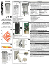
DESCRIZIONE DEL PRODOTTO
Il rivelatore TT19AM, è un dispositivo tripla-tecnologia progettato e realizzato per la pro-
tezione di ambienti esterni, ove sia prevista l’installazione ad un’altezza compresa tra 80
cm e 1,2 m.
È composto da due PIROELETTRICI PASSIVI, con lente di Fresnel, e da una MICROON-
DA a 10,525 GHz.
Il rivelatore ha una portata compresa tra 3 e 12 m.
PRESTAZIONI PRINCIPALI:
• elevataecaciadirilevazioneestabilitàrispettoaifalsiallarmi;
• sistema di antimascheramento a LED ATTIVI per la protezione del rivelatore e siste-
madiantiavvicinamentodiMW(settabilitramiteDIP);
• elevataimmunitàallapresenzadianimali,garantitadaunalgoritmotaratopernon
rilevareanimalinoaunatagliamedia.
AVVERTENZE
Prima di installare il rivelatore TT19AM tenere in considerazione i seguenti elementi:
• il rivelatore deve essere regolato in modo da evitare che la copertura dello stesso
coincidaconlapresenzadioggettiinmovimento;
• Ilsuolodell’areacopertanondevepresentarependenzesignicative(sivedailpara-
grafoREGOLAZIONEINFUNZIONEDELLAPENDENZADELSUOLO);
• il supporto dove viene montato deve essere rigido, non soggetto a vibrazioni e non
presentareanomalesporgenze/incavi;
• l’orientamentodelrivelatorenondeveintercettarelalucedirettadelsole;
• l’areadicoperturadelrivelatorenondeveinteressareampiesuperciriettenticome
ad esempio quelle metalliche.
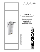
ALTEZZA DI INSTALLAZIONE E PET IMMUNITY
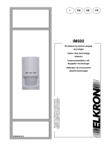
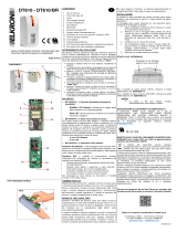
FISSAGGIO DEL RIVELATORE
L’altezza di installazione consigliata del rivelatore TT19AM è compresa tra 80 cm e 1,2 m
rispettoalsuolo.Nelcasovisialapossibilitàdipassaggiodianimalidomesticiall’interno
dell’area di copertura, si consiglia di prevedere un’altezza di montaggio del sensore supe-
riore all’altezza dell’animale da discriminare (FIG.3).Pereventualivericheintalsensosi
facciariferimentoalLEDGIALLOrelativoalfascioIR_F(FIG.2 e sottostante).
MontarelaSTAFFADIFISSAGGIOAMURO(FIG.4A) utilizzando tasselli e viti adatte al
tipodiparete;iforirealizzatidevonoesseredueeconcidereconi“FORIDIFISSAGGIO
STAFFA” evidenziati in FIG.4A.
Applicare gli O-ring (FIG.4A)intornoalletorrettecilindrichepresentisulla“STAFFADI
FISSAGGIOAMURO”alnedievitarel’inltrazionediacquaattraversoiforidelletorrette
stesse.Dopoavereinlatoilcavonell’apposito“PASSACAVOATENUTA”presentesul
fondo,applicareilfondostessodelrivelatoresullastaadissaggiofacendocoinciderele
torrettedissaggiodellastaaconiforicilindricipresentinelfondo.Ancorareilfondoalla
staatramitele4“VITIFISSAGGIOSTAFFA”agendodall’internodelfondo.
Acompletamentodell’installazioneedopoavereettuatoicollegamenti,farslittareilrive-
latorenelladirezionedellavitedichiusurasuperioreefareunaleggerapressioneversoil
basso (FIG.7).Avvitarelavitesuperioreequellainferioreperconsentirelachiusuratotale
del rilevatore.
COLLEGAMENTI
Cablare il CAVO DI IMPIANTO sulla morsettiera della SCHEDA DI INTERFACCIA secon-
do le indicazioni presenti in FIG.8 e 9.
Tramitei2PonticelliALLEOL1...4eTAMPEOL1...4eilPonticelloM(FIG.9), è possibile
selezionareleresistenzedinelineaperdoppiootriplobilanciamento.Leresistenze
sono collegate come nello schema. La linea proveniente dalla centrale va collegata con
un polo al morsetto <L-> e l’altro al morsetto <L+ ALL> o al morsettto <L+ MASK>. Con
il Ponticello M chiuso e collegando <L+ MASK> si ha il contatto Mask in serie al contatto
Tamper. In questa condizione è possibile applicare al morsetto MASK una resistenza del
valore richiesto dalla centrale (R3B FIG.9) per ottenere il triplo bilanciamento. Se non
viene selezionata nessuna resistenza e il ponticello M è aperto, i contatti TAMP, ALL
e MASK sono tutti indipendenti.
Unavoltaeseguiteleopportuneregolazioni,chiudereilrivelatoreserrandole2vitiap-
posite (una nella parte superiore subito sotto il tettuccio parapioggia ed una nella parte
inferioreinprossimitàdelprolodichiusuradelsensorestesso).
PRIMA ALIMENTAZIONE
Fornital’alimentazione,ilsensoreentrainfasediinizializzazione,durantelaqualei3LED
lampeggiano alternativamente.
Dopoquestafase(cheduracirca60secondi),ilsensoreentrainWalkTestper20minuti.
3
1
2
4
SPECIFICHE TECNICHE
CARATTERISTICHE / FUNZIONI PRINCIPALI
• Rivelatoretriplatecnologiadaesterno(duePIR+MW);
• GradodiProtezioneIP54
• ClasseAmbientaleEN50131-2-4:CLASSEIII
• GradoProtezioneEN50131-2-4:GRADO2
• DuesensoriPIRinfrarossodoppioelementoadaltaecienzaltratoallalucebianca;
• LenteFresnelapianiparallelistabilizzataairaggiUV;
• Antimascheramento a LED ATTIVI
• Sistemadiantiavvicinamento;
• Contenitoreinpolicarbonatoaltaqualità,stabilizzatoUV;
• Schedatropicalizzata;
• Compensazione dinamica della temperatura con rilevazione della temperatura reale
dell’ambiente;
• Pet immunity
Assorbimento Max:
Dimensioni senza
accessori:
12V +/- 3V
39mA
18mA
10.525 GHz
5 sec
100mA@24V
100mA @ 30V
-10°C / +55°C
95%
185 x 85 x 80mm
Alimentazione:
Assorb. Stand By:
Microonda:
Tempo Allarme:
Opto Relè:
Tamper:
Temperatura lavoro:
Umidità Ambientale:
Durante l’inizializzazione, evitare qualsiasi movimento nelle immediate vicinanze del rive-
latorestesso,alnedinoninciarel’AUTOTARATURAdelsistemadiantimascheramen-
to.Nelcasodimascheramento,sivisualizzeràillampeggiocontemporaneodeitreLED
(VERDE-BLU-GIALLO).
ANTIMASCHERAMENTO
LasensibilitàvieneimpostatatramiteildipswitchN.3:ANDPUROeANDTEMPORALE
(vedereilparagrafo“Settaggi”).Nell’ANDTEMPORALE,l’arcotemporaleall’internodel
qualevieneaccettatol’ANDdeisegnalidiIR_MedIR_Fèpiùristrettorispettoall’AND
PURO.QuestosignicachelasensibilitàdelrivelatoreinANDPUROèpiùaltarispetto
all’ANDTEMPORALE;quest’ultimo,difatto,risultaesseremaggiormenteottimizzatoper
l’immunitàPETepiùadattoalleinstallazioniincuicisonocriticitàinterminidipossibili
falsiallarmidiinfrarosso.
SENSIBILITÀ
7
Torretta di ssaggio - Fixing turret - Cylindre de xation
5
2
1
3
4
Allarme Blu - Alarm Blue - Alarme Bleue
Microonda Verde - Microwave green - Microonde vert
IR_F Giallo - Yellow - Jaune
IR_M Rosso - Red - Rouge
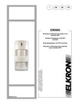
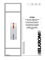
10 m
10 m
0 m
4 m 8 m 12 m 15 m
12 m
4 m 8 m 15 m
IR_F LED GIALLO
IR_M LED ROSSO
Visualizzazioni Led
Giallo IR_F Verde MW
Blu Allarme Rosso IR_M
POSIZIONAMENTO CORRETTO
Area di incertezza tra 12 e 15 m. Portata del rivelatore garantita: no a 12 metri.
Foro superiore ssaggio staffa - Upper bracket xing hole - Trou supérieur xation support
6
Area posteriore passacavo - Rear cable feed area - Partie postérieure serre-câble
10
O-ring - O-ring - Joint torique
8
Foro inferiore ssaggio staffa - Lower bracket xing hole - Trou inférieur xation support
9
Viti ssaggio staffa - Bracket xing screws - Vis xation support
13
Vite chiusura superiore - Upper closing screw - Vis fermeture supérieur
Passacavo a tenuta - Sealed cable - Serre-câble étanche
Scheda interfaccia - Interface board - Carte interface
Tamper
Ponticello M - Jumper M - Cavalier M
Cavo at - Flat cable - Connexion at
14
16
15
Viti ssaggio staffa - Bracket xing screws - Vis xation support
Resistenze di ne linea - End of line resistances - Résistances de n de ligne
18
17
21
Vite di regolazione suolo - Circuit position adjustment- Vis deréglage sol
19
Trimmer di regolazione - Trimmer - Trimmer de réglage
20
Dip switch - Dip switch - Commutateur
24
Connettore scheda di interfaccia - Interface board connector - Connecteur carte d’interface
22
IR_M
23
AM led attivi - AM active led - AM led actives
27
IR_F
25
Compensatore della temperatura - Temperature compensation - Compensateur de température
26
Microonda - Microwave - Microonde
30
Staffa a muro - Wall bracket - Support mural
28
Lente copriled - Led cover lens - Lentille couvre-led
29
Cavo at di connessione - Flat cable connection - Câble plat de branchement
Cover - Cover - Couverture
31
32 Linguetta di chiusura superiore - Upper closing tab - Languette de fermeture supérieure
Linguetta di chiusura inferiore - Lower closing tab - Languette de fermeture inférieure
33
11
12
FIG.3
PET IMMUNITY
OK
PET IMMUNITY
NO
4 m 8 m 12 m 15 m
Banda frequenza: 10,525 GHz 18 dBm
Potenza max trasmessa:
RIVELATORE TRIPLA
TECNOLOGIA DA ESTERNO
ALTEZZA INSTALLAZIONE 1,2 M
TT19AM ITALIANO
TRIPLE TECHNOLOGY
DETECTOR FOR OUTDOOR
INSTALLATION HEIGHT 1,2 m
DÉTECTEUR TRIPLE
TECHNOLOGIE D’EXTÉRIEUR
HAUTEUR INSTALLATION 1,2 m
DS80IM48-001C
FONDO RIVELATORE
DETECTOR BASE
FOND DÉTECTEUR
STAFFA FISSAGGIO A MURO
WALL FIXING BRACKET
SUPPORT DE FIXATION MURALE
FIG.5A FIG.5B
10 m
10 m
12 m
0 m
15 m
15 m
FIG.1
FIG.7
FIG.4A FIG.4B
FIG.2
13
16
6
5
10
17 18
8
7
12
9
23
25
26
24
27
21
22
19
20
14
15
11
FIG.6
28
30
29
31
32
33

WALK TEST
Prima di procedere con il WALK TEST, rimuovere la LENTE COPRIVITE per
permettereunamigliorevisualizzazione;laLENTECOPRIVITEverràripristinata
solo a calibrazione terminata.
Durantelafasedi“WalkTest”tuttiiledsarannovisibili.Rimarrannoinfunzione
per20minutidopolachiusuradelfrontalinoperpermetterelaverica/calibrazio-
nedelsensore.Trascorsoquestotemposaràvisualizzatosoloilleddiallarme
(amenochenonsiastataselezionatapreventivamentelafunzioneLED_DIP4
in posizione ON).
Per eseguire il Walk Test procedere come di seguito descritto:
1. vericarechelaportatadellamicroondasiaalmassimo(TRIMMERDIRE-
GOLAZIONEdiFIG.5Aruotatocompletamenteinsensoorario);
2. vericarelacontemporaneavisualizzazionedelLEDGIALLO(fascioIR_F)
edelLEDROSSO(fascioIR_M),muovendosiallamassimadistanzadel
sensore rispetto all’area che si vuole proteggere.
ATTENZIONE:
• se si visualizza il solo LED ROSSO, il rivelatore è puntato troppo in alto
rispetto al terreno, quindi slittare il circuito del sensore come in FIG.10B;
• se si visualizza il solo LED GIALLO, il rivelatore è puntato troppo in basso
rispetto al terreno, quindi slittare il circuito del sensore come in FIG.10A.
3. UnavoltavericatalacontemporaneitàdelLEDGIALLOeROSSO,regola-
relamicroonda,tramiteTRIMMERDIREGOLAZIONE,perlimitarelazona
di copertura alla distanza desiderata.
PORTATA
Perregolarelaportatadelrivelatore,agiresultrimmerpresentesulfondodelri-
velatore (FIG.5A).Ruotandoiltrimmerinsensoorariosiaumenteràlaportata;la
portata minima possibile è di circa 3 m, mentre quella massima garantita è di m
12. Per regolare la portata, simulare l’intrusione alla distanza massima deside-
rataeregolareiltrimmeranchésivengarilevatiapartiredalpuntodesiderato.
ATTENZIONE: se l’oggetto in movimento risulta essere particolarmente grande
(ad es. un’automobile, un camion, un animale da allevamento, ecc.) è possibile
che lo stesso venga rilevato anche a distanze superiori ai 12 m.
APPLICAZIONE CON SUOLO PERPENDICOLARE
L’otticadelrivelatoreèregolatadifabbricaperun’installazioneincuiilsuolosia
perpendicolarerispettoallasuaposizione.Siconsigliadinonmodicarequesta
regolazionepernonmetterearischiolacapacitàdirilevazione,inparticolareper
la discriminazione di animali domestici.
Unavoltaeseguiteleopportuneregolazioni(cablaggio,settaggiodipswitch,re-
golazione portata, applicazione di eventuali parzializzatori *), chiudere il rivela-
tore serrando le 2 viti apposite (una nella parte superiore subito sotto il tettuccio
parapioggiaedunanellaparteinferioreinprossimitàdelprolodichiusuradel
sensore stesso).
* LT19/20: parzializzatori dedicati ai rivelatori TT19AM e TT20AM
CHIUSURA DELL’INSTALLAZIONE
DIRETTIVA 2012/19/UE DEL PARLAMENTO EUROPEO E DEL CONSIGLIO del 4 luglio 2012 sui rifi
uti di apparecchiature elettriche ed elettroniche (RAEE).
Ilsimbolodelcassonettobarratoriportatosull’apparecchiaturaosullasuaconfezioneindi-
cacheilprodottoallanedellapropriavitautiledeveessereraccoltoseparatamentedagli
altririuti.L’utentedovrà,pertanto,conferirel’apparecchiaturagiuntaanevitaagliidonei
centricomunalidiraccoltadierenziatadeiriutielettrotecniciedelettronici.Inalternativa
alla gestione autonoma è possibile consegnare l’apparecchiatura che si desidera smaltire
al rivenditore, al momento dell’acquisto di una nuova apparecchiatura di tipo equivalente.
Pressoirivenditoridiprodottielettroniciconsuperciedivenditadialmeno400m2èinoltrepossibile
consegnare gratuitamente, senza obbligo di acquisto, i prodotti elettronici da smaltire con dimensione
massimainferiorea25cm.L’adeguataraccoltadierenziataperl’avviosuccessivodell’apparecchiatura
dismessa al riciclaggio, al trattamento e allo smaltimento ambientalmente compatibile contribuisce ad
evitarepossibilieettinegativisull’ambienteesullasaluteefavorisceilreimpiegoe/oriciclodeimateriali
di cui è composta l’apparecchiatura.
DICHIARAZIONE DI CONFORMITÀ
Ilfabbricante,URMETS.p.A.,dichiaracheiltipodiappa-
recchiatura radio: RIVELATORE TRIPLA TECNOLOGIA
DAESTERNOALTEZZA1,2mTT19AM,èconformealla
direttiva2014/53/UE.Iltestocompletodelladichiarazione
diconformitàUEèdisponibilealseguenteindirizzoInter-
net:www.elkron.com.
PAESI IN CUI LA FREQUENZA DEL PRODOTTO È LIMITATA O NON AMMESSA
SETTAGGI
DIP 1
DIP 2
DIP 3
Dip 1 OFF
Dip 3 ON -
Sensibilità (AND
PURO)
Dip 4 ON
LED
Dip 1 ON
Dip 2 ON
11
1
1
1
1
2
2
2
2
2
2
3
3
3
33
3
4
4
4
4
4
4
DIP 4
Antimascheramento disinserito
Pereseguire ivari settaggi agiresui dipswitchpresentinella parteposteriore
della scheda (Fig.5A). POSIZIONE DI DEFAULT DI TUTTI I DIP SWITCH: OFF
Vincola l’antimascheramento alla rilevazione
di un avvicinamento da parte della microonda.
Dip 3 OFF Sensibilità
(AND TEMPORALE)
Trascorso il tempo del “Walk Test” permette di elimi-
nare la visualizzazione del led allarme.
OFF
ON
OFF
ON
OFF
ON
OFF
ON
OFF
ON
OFF
ON
Antimascheramento inserito
PRODUCT DESCRIPTION
TT19AMdetectorisatriple-technologydevicedesignedandbuiltfortheprotectionofout-
doorenvironmentswhereinstallationisrequiredataheightofbetween80and120cm.
It consists of two PASSIVE PYROELECTRIC SENSORS, with Fresnel lenses, and a
10.525 GHz MICROWAVE.
Thedetectorhasarangeofbetween3and12m.
MAINFEATURES:
• highdetectioneciencyandstabilitytopreventfalsealarms;
• anACTIVELEDantimaskingsystemfordetectorprotectionandaMWproximityalert
system(settableviaDIP);
• highimmunitytothepresenceofanimals,guaranteedbyanalgorithmcalibratedtonot
detectanimalsbelowaveragesize.
WARNINGS
ThefollowingaspectsshouldbeconsideredbeforeinstallingTT19AM:
• thedetectormustbeadjustedsoastopreventitscoveragecrossingthepathofmoving
objects;
• thegroundinthecoveredareamustnothavesignicantslopes(seetheparagraphon
ADJUSTINGINRELATIONTOTHESLOPEOFTHEGROUND);
• thesupportonwhichthedetectorismountedmustberm,freefromvibrationsand
withnounusualprotrusions/recesses;
• thedetectormustbepositionedsothatitisnotexposedtodirectsunlight;
• thedetector’scoverageareashouldnotincludelargereectivesurfaces,suchassheet
metal.
INSTALLATION HEIGHT AND PET IMMUNITY
TherecommendedinstallationheightoftheTT19AMdetectorisbetween80cme1,2m
fromtheground.
Ifthereisthepossibilityofpetspassingwithinthecoveragearea,itisadvisabletoprovide
asensormountingheighthigherthantheheightoftheanimaltobediscriminated(FIG.3).
Foranychecksinthissense,refertotheYELLOWLEDrelatingtotheIR_Fbeam(FIG.
2andbelow).
FIXING THE DETECTOR
Mountthewallxingbracket(FIG.4A)withappropriatescrewsandplugsforthetypeof
wall;twoholesmustbedrilledaligningwiththe“Fixingbracketholes”showninFIG.4A. Fit
the O-RINGS (FIG.4A)aroundthecylindricalturretsonthewallxingbracket,inorderto
preventinltrationofwaterthroughtheturretholes.
Afterpassingthecablethroughthesealedcablegland(Fig.4B)onthebase,tthebase
ofthedetectortothexingbracket,aligningthexingturretsonthebracketwiththecylin-
dricalholesonthebase.Securethebasetothebracketwiththe4bracketxingscrews,
insertingthemfrominsidethebase.
Tocompletetheinstallation,aftermakingtheconnections,slidethedetectortowardsthe
upperclosingscrewandapplyslightpressureatthebottom(FIG.7). Tighten the upper and
lowerscrewstoenablecompleteclosureofthedetector.
CONNECTIONS
WiretheSYSTEM CABLEontheINTERFACEBOARDterminal blockaccordingto the
indications in FIG. 8 and 9.
Usingthe2JumpersALLEOL1...4andTAMPEOL1...4andtheJumperM(FIG.9),it
ispossibletoselecttheend-of-lineresistorsfordoubleortriplebalance.Theresistorsare
connectedasinthediagram.Thelinecomingfromthecontrolunitmustbeconnectedwith
one pole to the <L-> terminal and the other to the <L + ALL> terminal or to the <L + MASK>
terminal. With Jumper M closed and connecting <L + MASK> the Mask contact is in series
withtheTampercontact.InthisconditionitispossibletoapplytotheMASKterminala
resistorofthevaluerequestedbythecontrolunit(R3BFIG.9)toobtaintriplebalance.
If no resistor is selected and jumper M is open, the contacts TAMP, ALL and MASK
are all independent.
Once the appropriate adjustments have been made, close the detector by tightening the
2providedscrews(oneintheupperpartimmediatelyundertheraincoverandoneinthe
lowerpartnearthesensorclosingprole).
INITIAL POWER-UP
Whenthepowerisswitchedon,thesensorstartstheinitializationphase,duringwhichthe
3LEDsblinkalternately.Afterthisphase(whichlastsabout60seconds),thesensorgoes
intoWalkTestmodefor20minutes.
TECHNICAL SPECIFICATIONS
Max current:
Dimensions without
accessories:
12V +/- 3V
39mA
18mA
10.525 GHz
5 sec
100mA@24V
100mA @ 30V
-10°C / +55°C
95%
185 x 85 x 80mm
Power supply:
Stand By current:
Microwave:
Allarm time:
Opto Relay:
Tamper:
Working temperature:
Ambient humidity:
SPECIFICATIONS AND MAIN FUNCTIONS
• Tripletechnologyoutdoordetector(twoPIR+MW);
• ProtectionratingIP54;
• EnvironmentalClass:EN50131-2-4CLASSIII;
• Protectiongrade:EN50131-2-4GRADE2;
• Twohigh-efficiencydual-elementPIRsensorswithwhitelightfilters;
• FresnellenswithparallelplanesstabilizedtoUVrays;
• ActiveLEDantimasking;
• Proximityalertsystem;
• Highqualitypolycarbonatecontainer,UVstabilized;
• Tropicalizedcircuitboard;
• Dynamictemperaturecompensationwithrealambienttemperaturemeasurement;
• Pet immunity.
10 m
10 m
0 m
4 m 8 m 12 m 15 m
12 m
4 m 8 m 15 m
IR_F YELLOW LED
IR_M RED LED
Led displays
Yellow IR_F Green MW
Blue Alarm Red IR_M
CORRECT POSITIONING
Uncertainty area between 12 and 15 m. Guaranteed detector range: up to 12 meters.
Frequency range: 10,525 GHz 18 dBm
Max power trasmitted:
ENGLISH
NO
NO OK
FIG.10
PONTICELLO
ALLARME / AM
Se inserito mette in serie il relè
allarme con il relè antimascheramento
TAMP EOL
4
4
3
3
2
2
1
1
ALL EOL
Relè ALL
Relè MASK
Contatto TAMP
12V
TAMP
ALL
I
MASK
R3B
15K
5.1K
2.7K
1K
15K
5.1K
2.7K
1K M
L+ NC NC L-
M
L+ NC
R3B = resistenza triplo bilancia-
mento
USO DEI PONTICELLI PER RESISTENZE DI BILANCIAMENTO
E USCITA ANTIMASKING
FIG. 9
FIG. 8
A B
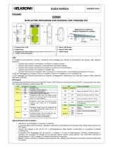
REGOLAZIONI IN FUNZIONE DELLA PENDENZA DEL SUOLO
In caso di pendenze del suolo agire sulla VITE DI REGOLAZIONE SUOLO
traslando la scheda rispetto alla vite stessa come evidenziato sotto.
• Terreno in salita: slittare il circuito come in 10A
• Terreno in discesa: slittare il circuito come in 10B
Eseguire una regolazione graduale per non rischiare di ruotare eccessivamente
ifascidirilevazione.Partirequindidallaposizionecentraleperpoitraslareilcir-
cuitoperpiccolistepnoadottenimentodellacondizionedesiderata.Unavolta
vericatolacontemporaneitàdelLEDGIALLOeROSSO,regolarelamicroonda
(tramite TRIMMER DI REGOLAZIONE) per limitare la zona di copertura alla
distanzadesiderata(comedescrittonelcapitolo“WALKTEST”).
MORSETTIERA
IPerusifuturi
+Ingresso alimentazione 12V
-
TAMP Tamper Normalmente chiuso
ALL Relè Allarme Normalmente chiuso
MASK Relè Antimask Normalmente chiuso
4 m
10 m
0 m
4 m 8 m 12 m 15 m
NO ALLARME - ERRORE
NO ALLARME
ERRORE
ALLARME
L’elevata inclinazione verso il basso del rivelatore
causa l’uso non corretto della funzione PET:
INCLINAZIONI CHE POSSONO CAUSARE RI-
LEVAZIONI NON CORRETTE
ESEMPI DI POSIZIONAMENTI NON CORRETTI
L’inclinazione scelta può limitare l’area che si vuole
rilevare
L’inclinazione scelta può limitare la capacità di in-
tervento del rivelatore
SUOLO PERPENDICOLARE
REGOLAZIONI IN FUNZIONE DELLA PENDENZA DEL SUOLO

CARACTÉRISTIQUES TECHNIQUES
Absorption max.:
Dimensions sans
accessoires :
12V +/- 3V
39mA
18mA
10.525 GHz
5 sec
100mA@24V
100mA @ 30V
-10°C / +55°C
95%
185 x 85 x 80mm
Alimentation :
Absorb. stand By :
Microonde :
Temps Alarme :
Opto Relai :
Tamper :
Température de fonc-
tionnement :
Humidité ambiante:
CARACTÉRISTIQUES / FONCTIONS PRINCIPALES
• Détecteuràtripletechnologied’extérieur(deuxPIR+MW);
• DegrédeprotectionIP54
• ClasseenvironnementaleEN50131-2-4:CLASSEIII
• DegréprotectionEN50131-2-4:DEGRÉ2
• DeuxdétecteursPIRàinfrarougesàdoubleélémentàhauteecacité,ltréàlalu-
mièreblanche;
• LentilledeFresnelàplansparallèlesstabiliséeauxUV;
• AntimasquageàLEDACTIVES
• Systèmeanti-approche;
• Boîtierenpolycarbonatedehautequalité,stabiliséauxUV;
• Cartetropicalisée;
• Compensationdynamiquedelatempératureavecmesuredelatempératureambiante
réelle;
• Immunitéauxanimaux
AVERTISSEMENTS
Avantd’installerledétecteurTT19AM,prendreencomptelesélémentssuivants:
• ledétecteurdoitêtreréglédefaçonàcequesacouverturenerencontrepasd’objets
enmouvement;
• Lesoldelazonecouvertenedoitpasprésenterdepenteimportante(voirlepara-
grapheRÉGLAGEENFONCTIONDELADÉCLIVITÉDUSOL);
• lesupportsurlequelilestmontédoitêtrerigide,ilnedoitpasêtresujetàdesvibra-
tionsetnedoitpasprésenterdesaillies/cavitésanormales;
• l’orientationdudétecteurnedoitpasintercepterlalumièredirectedusoleil;
• lazonedecouverturedudétecteurnedoitpasincluredegrandessurfacesrééchis-
santes,métalliquesparexemple.
HAUTEUR D’INSTALLATION ET IMMUNITÉ AUX ANIMAUX
Lahauteurd’installationrecommandéedudétecteurTT19AM est comprise entre 80 cm
et1,2mau-dessusdusol.S’ilexisteunepossibilitédepassaged’animauxdomestiques
danslazonedecouverture,ilestconseillédeprévoirdemonterledétecteuràunehau-
teursupérieureàcelledesanimauxàignorer(FIG. 3).Pourd’éventuellesvérications
en ce sens, faire référence à la LED JAUNE relative au faisceau IR_F (FIG. 2 et au
dessous).
10 m
10 m
0 m
4 m 8 m 12 m 15 m
12 m
4 m 8 m 15 m
IR_F LED JAUNE
IR_M LED ROUGE
Visualisations LED
Jaune IR_F Vert MW
Bleu Alarme Rouge IR_M
POSITIONNEMENT CORRECT
Zone d’incertitude entre 12 et 15 m. Portée garantie du détecteur: jusqu'à 12 m.
SETTING
DIP 1
DIP 2
DIP 3
Dip 1 OFF
Dip 3 ON
Sensitivity
(PURE AND)
Dip4ON
LED
Dip 1 ON
Dip 2 ON
11
1
1
1
1
2
2
2
2
2
2
3
3
3
33
3
4
4
4
4
4
4
DIP 4
Antimasking disabled
To implement the various settings, adjust the dipswitches on the back of the
circuit board (Fig.5A). DEFAULT POSITION OF ALL DIP SWITCHES: OFF
Links the antimasking to proximity detection by the
microwave.
Dip 3 OFF
Sensitivity
(TEMPORAL AND)
After the “Walk Test” time has elapsed, it allows to
eliminate the display of the alarm led.
OFF
ON
OFF
ON
OFF
ON
OFF
ON
OFF
ON
OFF
ON
Antimasking enabled
Oncethenecessaryadjustments(wiring,dipswitchsetting,rangeadjustment,application
oflensmasks*)havebeenmade,closethedetectorbytighteningthetwoscrews(oneat
thetopimmediatelybelowtherainprotectioncoverandoneinthelowerpartbesidethe
sensorclosingprole).
* LT19/20: dedicated lens masks for detectors TT19AM and TT20AM
WALK TEST
BeforeproceedingwiththeWALKTEST,removetheSCREWCOVERLENS
toallowabetterview;theSCREWCOVERLENScanonlyberestoredafter
calibration.
Duringthe“WalkTest”,alltheLEDswillbevisible.Theywillremaininfunction
for20minutesafterthefrontpanelhasbeenclosedtoallowtesting/calibration
ofthesensor.Afterthis,onlythealarmLEDwillbevisible(unlesstheOFF_DIP
4LEDfunctionhasbeenpreviouslyselected).
ToperformtheWalkTestproceedasfollows:
1. checkthatthemicrowaverangeisatmaximum(REGULATIONTRIMMER
ofFIG.5Arotatedcompletelyclockwise);
2. checkthesimultaneousdisplayoftheYELLOWLED(IR_Fbeam)andthe
REDLED(IR_Mbeam),movingtothemaximumdistanceofthesensor
fromtheareayouwanttoprotect.
ATTENTION:
• if only the RED LED is displayed, the detector is pointed too high with
respect to the ground, therefore slide the sensor circuit as in FIG.10B;
• if only the YELLOW LED is displayed, the detector is pointed too low
with respect to the ground, so slide the sensor circuit as in FIG.10A.
3. OnceyouhavecheckedthattheYELLOWandREDLEDsareatthesame
time,adjustthemicrowaveusingtheADJUSTMENTTRIMMERtolimitthe
coverage area to the desired distance.
CAPACITY
Therangeofthedetectorcanbeadjustedviathetrimmeronthebackofthede-
tector (FIG.5A).Turningthetrimmerinaclockwisedirectionincreasestherange;
theminimumpossiblerangeisabout3m,whilethegreatestguaranteedrangeis
12 m. To adjust the range, simulate the intrusion at the maximum desired distan-
ceandadjustthetrimmersothatitisdetectedstartingfromthedesiredpoint.
ATTENTION:
if the moving object is particularly large (eg. a car, a truck, a farm animal, etc.) it’s
possible that it can be detected even at distances greater than 12 m.
ADJUSTING IN RELATION TO THE SLOPE OF THE GROUND
CLOSING THE INSTALLATION
Once the detector is closed, avoid any movement in the immediate vicinity
ofthedetectorinordernottoinvalidatetheAUTO-CALIBRATIONoftheanti-
maskingsystem.Ifthedetectorismasked,thethreeLEDs(GREEN,BLUEand
YELLOW)willash.
ANTIMASKING
ThesensitivityissetbymeansofdipswitchN.3:PUREANDandTEMPORAL
AND(seethe“Settings”paragraph).IntheTEMPORALAND,thetimeframe
withinwhichtheANDoftheIR_MandIR_Fsignalsisacceptedismorerestri-
ctedthan the PUREAND.Thismeans that thedetector sensitivity inPURE
ANDishigherthaninTEMPORALAND;thelatter,infact,ismoreoptimizedfor
PETimmunityandmoresuitableforinstallationswheretherearecriticalissues
intermsofpossiblefalseinfraredalarms.
SENSITIVITY
In the case of sloping ground, adjust the GROUNDADJUSTMENT SCREW,
slidingtheboardinrelationtothescrewasshownbelow.
• Uphillslope:slidethecircuitasshowninFIG.10A
• Downhillslope:slidethecircuitasshowninFIG.10B
• Make a gradual adjustment to avoid rotating the detection beams excessi-
vely.Startfromacentralpositionandthenslidethecircuitinsmallsteps
untilthedesiredconditionisobtained.Oncetheyellowandredledsswitch
onatthesametime,adjustthemicrowave(viatheADJUSTMENTTRIM-
MER) to limit the coverage area to the desired distance (as described in the
“WALKTEST”section).
APPLICATION WITH PERPENDICULAR GROUND
Thedetectoropticsarefactoryadjustedforaninstallationinwhichtheground
is perpendicular to its position (as below). It is recommended not to change this
setting in order not to jeopardize the detection capability, in particular for the
discriminationofpets.
NO
NO OK
FIG.10
AB
SIMPLIFIED EU DECLARATION OF
CONFORMITY
Hereby,URMETS.p.A. declares that theradio equip-
menttype:TRIPLETECHNOLOGYDETECTORFOR
OUTDOORHEIGHT1,2 mTT19AM is in compliance
withDirective2014/53/EU.ThefulltextoftheEUdecla-
rationofconformityisavailableatthefollowinginternet
address:www.elkron.com.
DIRECTIVE 2012/19/EU OF THE EUROPEAN PARLIAMENT AND OF THE COUNCIL of 4 July
2012 on waste electrical and electronic equipment (WEEE).
Thesymbolofthecrossed-outwheeledbinontheproductoronits
packagingindicatesthatthisproductmustnotbedisposedofwithyourotherhousehold
waste.Instead,itisyourresponsibilitytodisposeofyourwasteequipmentbyhandingit
overtoadesignatedcollectionpointfortherecyclingofwasteelectricalandelectronic
equipment.Theseparatecollectionandrecyclingofyourwasteequipmentatthetimeof
disposalwillhelptoconservenaturalresourcesandensurethatitisrecycledinamanner
thatprotectshumanhealthandtheenvironment.Formoreinformationaboutwhereyou
candropoffyourwasteequipmentforrecycling,pleasecontactyourlocalcityoffice,your
householdwastedisposalserviceortheshopwhereyoupurchasedtheproduct.
COUNTRIES WHERE THE PRODUCT’S FREQUENCY IS RESTRICTED
OR NOT PERMITTED
4 m
10 m
0 m
4 m 8 m 12 m 15 m
NO ALARM - ERROR
NO ALARM:
ERROR
ALARM
The high downward inclination of the detector cau-
ses incorrect use of the Pet Immunity function:
INCLINATION WHICH MAY CAUSE INCOR-
RECT DETECTION
EXAMPLES OF INCORRECT POSITIONING
The selected inclination may limit the area to be de-
tected:
The selected inclination may limit the intervention
capacity of the detector:
PERPENDICULAR GROUND
ADJUSTMENT TO THE SLOPE OF THE GROUND
USE OF JUMPERS FOR BALANCE RESISTORS AND ANTIMASKING
OUTPUT
R3B= triple balance resistor
Relay ALL
FIXATION DU DETECTEUR
MonterleSUPPORTDEFIXATIONMURALE(FIG. 4A) en utilisant des chevilles et des
visadaptéesautypedemur;lestrousréalisésdoiventêtreaunombrededeuxetdoivent
coïncideraveclesTROUSDEFIXATIONDUSUPPORTindiquéssurlaFIG. 4A.
Mettre en place les joints toriques (FIG. 4A)autourdescylindressurleSUPPORTDE
FIXATIONMURALEand’éviterlesinltrationsd’eauàtraverslestrousdescylindres.
AprèsavoirenlélecâbledansleSERRE-CÂBLEétancheprévuàceteetsurlefond,
appliquerlefonddudétecteursurlesupportdexationenfaisantcoïnciderlescylindres
dexationdusupportaveclestrouscylindriquesprésentsurlefond.Fixerlefondau
supportàl’aidedes4VISDEFIXATIONDUSUPPORT,del'intérieurdufond.
Unefoisl’installationterminéeetaprèsavoireectuélesbranchements,faireglisserle
détecteurverslavisdefermeturesupérieureetexercerunelégèreprésenceverslebas
(FIG. 7).Serrerlesvissupérieureetinférieurepourpermettrelafermeturecomplètedu
détecteur.
TERMINAL BOARD
IForfutureuse
+12Vpowersupplyinput
-
TAMP Tamper Normally closed
ALL Alarm Relay Normally closed
MASK Antimask Relay Normally closed
FIG. 8
PREMIÈRE ALIMENTATION
Unefoisl’alimentationfournie,ledétecteursemetenphased'initialisation,pendantla-
quelleles3LEDclignotentalternativement.Aprèscettephase(quidureenviron60se-
condes),ledétecteurpasseàlaphasedeWalkTestpendant20minutes.
Bande radiofréq. : 10,525 GHz 18 dBm
Puiss. max transmise:
DESCRIPTION DU PRODUIT
LedétecteurTT19AMestundispositifàtripletechnologieconçuetfabriquépourlapro-
tectiondesenvironnementsextérieurs,quiprévoituneinstallationàunehauteurcomprise
entre 80 cm et 1,2 m.
IlsecomposededeuxélémentsPIROÉLECTRIQUESPASSIFS,aveclentilledeFresnel
etd’uneMICRO-ONDEà10,525GHz.
Ledétecteurauneportéecompriseentre3et12m.
PERFORMANCES PRINCIPALES :
• hauteecacitédedétectionetstabilitéenprésencedefaussesalarmes;
• systèmeanti-masquageàLEDACTIVESpourlaprotectiondudétecteuretsystème
anti-approcheMW(sélectionnablesaveccommutateurs);
• hauteimmunitéàlaprésenced’animaux,garantieparunalgorithmeréglépourne
pasdétecterlesanimauxjusqu’àunetaillemoyenne.
FRANÇAIS
FIG. 9

RÉGLAGES EN FONCTION DE LA DÉCLIVITÉ DU SOL
Elkron è un marchio commerciale di - is a commercial trademark of - est une marque
commercialedeUrmetS.p.A.-ViaBologna,188/C-10154Torino(TO)Italia
Tel.+39.0113986711Fax0113986703
www.elkron.com-info@elkron.com MADE IN ITALY
Encasdedéclivitédusol,intervenirsurlaVISDERÉGLAGEDUSOLendépla-
çantlacarteparrapportàlaviscommeindiquésurlesFIG. 10.
• Terrainenmontée:faireglisserlecircuitcommeindiquéenA.
• Terrainendescente:faireglisserlecircuitcommeindiquéenB.
Eectuerunréglageprogressifandenepasrisquerdefairetournerexcessi-
vementlesfaisceauxdedétection.Partirdelapositioncentralepour déplacer
ensuiteprogressivementlecircuitjusqu’àcequesoitobtenuelaconditionvoulue.
Après avoir vériée la simultanéité des LED JAUNE et ROUGE, régler la mi-
croonde,àl’aideduTRIMMERDERÉGLAGE,pourlimiterlazonedecouverture
àladistancevoulue(commeindiquédanslechapitre«WALKTEST»).
SOL PERPENDICULAIRE
L’optiquedudétecteurestrégléeenusinepouruneinstallationaveclesolestper-
pendiculaireàsaposition(imageci-dessous).Ilestconseillédenepasmodier
ceparamètreandenepascompromettrelacapacitédedétection,notamment
pour ignorer les animaux domestiques.
BORNIER
IPourutilisationsfutures
+Arrivéealimentation12V
-
TAMP Tampernormalementfermé
ALL Relaialarmenormalementfermé
MASK Relai anti-masquage normale-
mentfermé
WALK TEST
AvantdeprocéderauWALKTEST,retirerlaLENTILLECOUVRE-VISpourper-
mettre une meilleure visualisation ; la LENTILLE COUVRE-VIS est remise en
placeunefoislacalibrageterminé.
Pendantlaphasede«WalkTest», touteslesLED sontvisibles.Elles restent
actives pendant 20 minutes après la fermeture de la façade pour permettre le
contrôle/calibrage du détecteur. Une fois cette durée écoulée, seule la LED
d’alarmeresteachée(àmoinsquelafonctionLED_DIP4aitétépréalablement
régléesurON).PoureectuerleWalkTest,procédercommesuit:
1. s’assurerquelaportéedelamicroondesoitaumaximum(Trimmerderé-
glage de la FIG. 5Atournéàfonddanslesensdesaiguillesd’unemontre);
2. vérierlavisualisationsimultanéedelaLEDJAUNE(faisceauIR_F)etde
laLEDROUGE(faisceauIR_M)ensedéplaçantàladistancemaximaledu
détecteurparrapportàlazoneàprotéger.
ATTENTION :
• siseulelaLEDROUGEestachée,ledétecteurestdirigétrophautparrap-
portausol,faireglisserlecircuitdudétecteurcommeindiquésurlaFIG. 10B ;
• siseulelaLEDJAUNEestachée,ledétecteurestdirigétropbasparrapport
ausol,faireglisserlecircuitcommeindiquésurlaFIG. 10A.
3. Aprèsavoir vériée la simultanéité des LED JAUNE et ROUGE, régler la
microonde, à l’aide du TRIMMER DE RÉGLAGE, pour limiter la zone de
couvertureàladistancevoulue.
PORTÉE
Pourréglerlaportéedudétecteur,intervenirsurletrimmersituéaudosdudé-
tecteur (FIG. 5A). En tournant le trimmer dans le sens des aiguilles d’une montre,
laportéeaugmente;laportéeminimumestd’environ3metlaportéemaximum
garantieestde12m.Pourréglerlaportée,simulerl’intrusionàladistancemaxi-
malevoulueetréglerletrimmerdemanièreanqueladétectionintervienneà
partir du point voulu.
ATTENTION : si l’objet en mouvement est particulièrement grand (par exemple
unevoiture,uncamion,unanimaldeferme,etc.),ilestpossiblequ’ilsoitdétecté
ycomprisàdesdistancessupérieuresà12m.
Pendantl’initialisation,évitertoutmouvementàproximitéimmédiatedudétecteur
lui-même, an de ne pas invalider l’AUTO-CALIBRAGE du système anti-mas-
quage.Encasdemasquage,lestroisLED(VERT-BLEU-JAUNE)semettentà
clignotersimultanément.
ANTI-MASQUAGE
Lasensibilitéestrégléeaumoyenducommutateurn°3:ANDPURetANDTEM-
POREL(voirleparagraphe«Réglages»).Surl’ANDTEMPOREL,l’intervallede
tempspendantlequelleANDdessignauxIR_MetIR_Festacceptéestpluscourt
parrapportauANDPUR. Celasignie quelasensibilité dudétecteurenAND
PURestplusélevéequ’enANDTEMPOREL;defait,cedernierestdavantage
optimisépourl’immunitéPET(animaux)etestmieuxadaptéauxinstallationsqui
présententdespointscritiquesentermesdefaussesalarmesd'infrarouge.
SENSIBILITÉ
Unefoislesréglagesappropriéseectués(câblage,réglagedescommutateurs,réglage
delaportée,applicationd’éventuelspartialisateurs*),fermerledétecteurenserrantles
2vis(unesurlapartiesupérieurejustesouslavisièredeprotectioncontrelapluieetune
surlapartieinférieureprèsduproldefermeturedudétecteur).
* LT19/20:partialisateursdédiésauxdétecteursTT19AM et TT20AM
FERMETURE DE L’INSTALLATION
DÉCLARATION DE CONFORMITÉ
Lefabricant,URMETS.p.A.,déclarequeletyped’appareilradio:DÉTECTEUR À TRIPLE
TECHNOLOGIE D’EXTÉRIEUR HAUTEUR 1,2 m TT19AM, est conforme à la direc-
tive2014/53/UE.Le textecompletde ladéclarationdeconformitéUE estdisponibleà
l’adresseInternetsuivante:www.elkron.com.
CAVALIER M (Alarme / AM)
S'il est présent, le CAVALIER M
met en série le relai d'alarme
avec le relai anti-masquage.
TAMP EOL
4
4
3
3
2
2
1
1
ALL EOL
Relai
ALL
Relai
MASK
contact TAMP
12V
TAMP
ALL
I
MASK
R3B
15K
5.1K
2.7K
1K
15K
5.1K
2.7K
1K
L+ NC NC L-
M
L+ NC
R3B=résistancetripleéquilibrage
UTILISATION DES CAVALIERS POUR RÉSISTANCES D'ÉQUILIBRAGE
ET SORTIE ANTI-MASQUAGE
FIG. 9
Détecteurconnectéàunecentraleantivolsurlesbornesd’alimentation(V+/V-)etsur
l'entréed'alarme(IN)avecdesrésistancespourledoubleéquilibrage.
RÉGLAGES
COMM. 1
COMM. 2
COMM. 3
Dip 1 OFF
ON = Sensibilité
(AND PUR)
ON
DIODES
Dip 1 ON
Dip 2 ON
11
1
1
1
1
2
2
2
2
2
2
3
3
3
33
3
4
4
4
4
4
4
COMM. 4
Anti-masquage désactivée
Poureectuerlesdiérentsréglages,utiliserlescommutateurssituésàl’arrière
de la carte (Fig. 5A). POSITION PAR DÉFAUT COMMUTATEURS : OFF
Conditionne l’anti-masquage à la
détection d’une approche par la micro-
onde.
OFF = Sensibilité
(AND TEMPOREL)
Une fois le temps du « Walk Test » écoulé, per-
met d’éliminer la visualisation de la led d’alarme.
OFF
ON
OFF
ON
OFF
ON
OFF
ON
OFF
ON
OFF
ON
Anti-masquage activée
TAMP EOL
1
1
1K
2.7K
5.1K
15K
2
2
3
3
4
4
ALL EOL
Relè ALL
Relè MASK
Contatto TAMP
NC L+
ALL
L- NC
TAMP
12V
INC L+
MASK
M
R3B
+V -V IN
centrale antifurto
Collegamenti sulla
1K
2.7K
5.1K
15K
R3B = Resistenza
triplo bilanciamento
BRANCHEMENTS
BrancherleCÂBLEDESYSTÈMEsurlebornierdelaCARTED’INTERFACEen
suivant les indications des FIG. 8 et 9.
Àl’aidedes2cavaliersALLEOL1...4etTAMPEOL1...4etducavalierM(FIG. 9),
ilestpossibledesélectionnerlesrésistancesdendelignepourundoubleou
tripleéquilibrage.Lesrésistancessontbranchéescommeindiquésurleschéma.
Unpôledelaligneprovenantdel’unitécentraledoitêtrebranchéàlaborne<L->
etl'autreàlaborne<L+ALL>ouàlaborne<L+MASK>.AveclecavalierMfermé
etenbranchant<L+MASK>,l’onobtientlecontactMaskensériesurlecontact
Tamper.Danscette condition,ilestpossibled’appliquerà laborneMASKune
résistancedelavaleurrequiseparl’unitécentrale(R3B FIG. 9) pour obtenir le
tripleéquilibrage.Si aucune résistance n’est sélectionnée et si le cavalier M
est ouvert, les contacts TAMP, ALL et MASK sont tous indépendants.
Unefoislesréglagesappropriéseectués,fermerledétecteurenserrantles2vis
(unesurlapartiesupérieurejustesouslavisièredeprotectioncontrelapluieet
unesurlapartieinférieureprèsduproldefermeturedudétecteur).
ESEMPIO DI COLLEGAMENTO - CONNECTION EXAMPLE
- EXEMPLE DE BRANCHEMENT
Rivelatorecollegatoaunacentraleantifurtosuimorsettidialimentazione(V+/V-)e
sull’ingresso allarme (IN), con resistenze per il doppio bilanciamento.
Detector connected to a burglar alarm control unit on the power supply terminals (V+
/ V-) and on the alarm input (IN), with resistors for double balance.
1 - ALL
1 - MASK
2 - TAMP
2 - Contatto - Contact - Contact
3-Collegamentisullacentraleantifurto-Connections on barglar alarm control unit -
Connexions sur la centrale d’alarme antivol
4-R3B=Resistenzatriplobilanciamento-Triple balance resistor-Résistancetriple
équilibrage
3
4
1 - Relè - Relay - Relai
DS80IM48-001C
NON
NON OK
FIG.10
AB
LES BONS GESTES DE MISE AU REBUT DE CE PRODUIT (Déchets d’équipements
électriques et électroniques)
Cesymboleapposésurleproduit,sesaccessoiresousadocumentationin-
diqueque nile produit,nises accessoiresélectroniques usagés(chargeur,
casqueaudio,câbleUSB,etc.),nepeuventêtrejetésaveclesautresdéchets
ménagers.Lamiseaurebutincontrôléedesdéchetsprésentantdesrisques
environnementauxetdesantépublique,veuillezséparervosproduitsetac-
cessoiresusagésdesautresdéchets.Vousfavoriserezainsilerecyclagedela
matièrequilescomposedanslecadred’undéveloppementdurable.
PAYS DANS LESQUELS LA FRÉQUENCE DU PRODUIT EST LIMITÉE OU
NON AUTORISÉE
FIG.9
4 m
10 m
0 m
4 m 8 m 12 m 15 m
PAS D’ALARME - ERREUR
PAS D’ALARME -
ERREUR
ALARME
Une forte inclinaison du détecteur vers le bas est
source de mauvaise utilisation de la fonction PET :
INCLINAISONS QUI PEUVENT ENTRAÎNER DE
MAUVAISES DÉTECTIONS
EXEMPLES DE MAUVAIS POSITIONNEMENTS
L’inclinaison choisie peut limiter la zone à couvrir.
L’inclinaison choisie peut limiter la capacité d’inter-
vention du détecteur.
1/4