
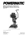
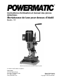
Operating Instructions and Parts Manual
Deluxe Bench-top Mortiser
Model: 701
Shown with optional chisel/bit sets
For serial no. 18077010001 and higher
Powermatic
427 New Sanford Road
LaVergne, Tennessee 37086 Part No. M-1791310
Ph.: 800-274-6848 Revision D1 12/2018
www.powermatic.com Copyright © 2018 Powermatic
This .pdf document is bookmarked

2
Warranty and Service
Powermatic
®
warrants every product it sells against manufacturers’ defects. If one of our tools needs service or
repair, please contact Technical Service by calling 1-800-274-6846, 8AM to 5PM CST, Monday through Friday.
Warranty Period
The general warranty lasts for the time period specified in the literature included with your product or on the official
Powermatic branded website.
Powermatic products carry a limited warranty which varies in duration based upon the product. (See chart
below)
Accessories carry a limited warranty of one year from the date of receipt.
Consumable items are defined as expendable parts or accessories expected to become inoperable within a
reasonable amount of use and are covered by a 90 day limited warranty against manufacturer’s defects.
Who is Covered
This warranty covers only the initial purchaser of the product from the date of delivery.
What is Covered
This warranty covers any defects in workmanship or materials subject to the limitations stated below. This warranty
does not cover failures due directly or indirectly to misuse, abuse, negligence or accidents, normal wear-and-tear,
improper repair, alterations or lack of maintenance. Powermatic woodworking machinery is designed to be used with
Wood. Use of these machines in the processing of metal, plastics, or other materials outside recommended
guidelines may void the warranty. The exceptions are acrylics and other natural items that are made specifically for
wood turning.
Warranty Limitations
Woodworking products with a Five Year Warranty that are used for commercial or industrial purposes default to a
Two Year Warranty. Please contact Technical Service at 1-800-274-6846 for further clarification.
How to Get Technical Support
Please contact Technical Service by calling 1-800-274-6846. Please note that you will be asked to provide proof
of initial purchase when calling. If a product requires further inspection, the Technical Service representative will
explain and assist with any additional action needed. Powermatic has Authorized Service Centers located throughout
the United States. For the name of an Authorized Service Center in your area call 1-800-274-6846 or use the Service
Center Locator on the Powermatic website.
More Information
Powermatic is constantly adding new products. For complete, up-to-date product information, check with your local
distributor or visit the Powermatic website.
How State Law Applies
This warranty gives you specific legal rights, subject to applicable state law.
Limitations on This Warranty
POWERMATIC LIMITS ALL IMPLIED WARRANTIES TO THE PERIOD OF THE LIMITED WARRANTY FOR EACH
PRODUCT. EXCEPT AS STATED HEREIN, ANY IMPLIED WARRANTIES OF MERCHANTABILITY AND FITNESS
FOR A PARTICULAR PURPOSE ARE EXCLUDED. SOME STATES DO NOT ALLOW LIMITATIONS ON HOW
LONG AN IMPLIED WARRANTY LASTS, SO THE ABOVE LIMITATION MAY NOT APPLY TO YOU.
POWERMATIC SHALL IN NO EVENT BE LIABLE FOR DEATH, INJURIES TO PERSONS OR PROPERTY, OR
FOR INCIDENTAL, CONTINGENT, SPECIAL, OR CONSEQUENTIAL DAMAGES ARISING FROM THE USE OF
OUR PRODUCTS. SOME STATES DO NOT ALLOW THE EXCLUSION OR LIMITATION OF INCIDENTAL OR
CONSEQUENTIAL DAMAGES, SO THE ABOVE LIMITATION OR EXCLUSION MAY NOT APPLY TO YOU.
Powermatic sells through distributors only. The specifications listed in Powermatic printed materials and on the official
Powermatic website are given as general information and are not binding. Powermatic reserves the right to effect at
any time, without prior notice, those alterations to parts, fittings, and accessory equipment which they may deem
necessary for any reason whatsoever.
Product Listing with Warranty Period
90 Days – Parts; Consumable items
1 Year – Motors, Machine Accessories
2 Year – Woodworking Machinery used for industrial or commercial purposes
5 Year – Woodworking Machinery
NOTE: Powermatic is a division of JPW Industries, Inc. References in this document to Powermatic also apply to
JPW Industries, Inc., or any of its successors in interest to the Powermatic brand.

3
Table of Contents
Warranty and Service .................................................................................................................................... 2
Table of Contents .......................................................................................................................................... 3
Warnings ....................................................................................................................................................... 4
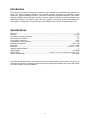
Introduction ................................................................................................................................................... 6
Specifications ................................................................................................................................................ 6
Unpacking ..................................................................................................................................................... 7
Contents of the Mortiser Carton ................................................................................................................ 7
Assembly ....................................................................................................................................................... 7
Gib Screws ................................................................................................................................................ 7
Operating Handle ...................................................................................................................................... 8
Gib Adjustment .......................................................................................................................................... 8
Overview – Chuck Extension .................................................................................................................... 9
Installing the Chuck Extension .................................................................................................................. 9
Installing Chisel and Auger ...................................................................................................................... 10
Securing Mortiser to Work Bench ............................................................................................................ 11
Tool Holder .............................................................................................................................................. 11
Diamond Sharpening Cone ..................................................................................................................... 11
Electrical ...................................................................................................................................................... 11
115V/230V Operation .............................................................................................................................. 11
Power Connection ................................................................................................................................... 11
Grounding Instructions ............................................................................................................................ 12
Operating Controls ...................................................................................................................................... 12
Start/Stop Switch ..................................................................................................................................... 12
Adjustments ................................................................................................................................................ 12
Depth Stop Adjustment............................................................................................................................ 12
Chisel Parallel to Workpiece ................................................................................................................... 13
Fence and Clamp .................................................................................................................................... 14
Fence Adjustment ................................................................................................................................ 14
Hold-down Clamp ................................................................................................................................ 14
Operation..................................................................................................................................................... 15
Rotating Column ...................................................................................................................................... 15
Maintenance ................................................................................................................................................ 16
General .................................................................................................................................................... 16
Sharpening Chisel and Auger ................................................................................................................. 16
Auger.................................................................................................................................................... 16
Chisel ................................................................................................................................................... 16
Handle Position Adjustment .................................................................................................................... 12
Lubrication ................................................................................................................................................... 16
Storage ........................................................................................................................................................ 16
701 Mortiser Assembly Drawing ................................................................................................................. 17
701 Mortiser Parts List ................................................................................................................................ 18
Wiring Diagram for 701 Mortiser ................................................................................................................. 20
Optional Accessories .................................................................................................................................. 20
Ordering Replacement Parts....................................................................................................................... 20
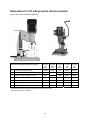
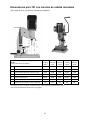
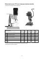
Dimensions for 701 with premium chisels mounted ................................................................................... 21

4
Warnings
1. Read and understand the entire owner's manual before attempting assembly or operation.
2. Read and understand the warnings posted on the machine and in this manual. Failure to comply with
any of these warnings may cause serious injury.
3. Replace the warning labels if they become obscured or removed.
4. This mortiser is designed and intended for use by properly trained and experienced personnel only. If
you are not familiar with the proper and safe operation of a mortiser, do not use until proper training
and knowledge have been obtained.
5. Do not use this mortiser for other than its intended use. If used for other purposes, Powermatic
disclaims any real or implied warranty and holds itself harmless from any injury that may result from
that use.
6. Always wear approved safety glasses/face shields while using this mortiser. Everyday eyeglasses
only have impact resistant lenses; they are not safety glasses.
7. Before operating this mortiser, remove tie, rings, watches and other jewelry, and roll sleeves up past
the elbows. Remove all loose clothing and confine long hair. Non-slip footwear or anti-skid floor strips
are recommended. Do not wear gloves.
8. Wear ear protectors (plugs or muffs) during extended periods of operation.
9. Do not operate this machine while tired or under the influence of drugs, alcohol or any medication.
10. Make certain the switch is in the OFF position before connecting the machine to the power supply.
11. Make certain the machine is properly grounded.
12. Make all machine adjustments or maintenance with the machine unplugged from the power source.
13. Remove adjusting keys and wrenches. Form a habit of checking to see that keys and adjusting
wrenches are removed from the machine before turning it on.
14. Keep safety guards in place at all times when the machine is in use. If removed for maintenance
purposes, use extreme caution and replace the guards immediately.
15. Make sure the mortiser is firmly secured to the floor or bench before use.
16. Check damaged parts. Before further use of the machine, a guard or other part that is damaged
should be carefully checked to determine that it will operate properly and perform its intended
function. Check for alignment of moving parts, binding of moving parts, breakage of parts, mounting
and any other conditions that may affect its operation. A guard or other part that is damaged should
be properly repaired or replaced.
17. Provide for adequate space surrounding work area and non-glare, overhead lighting.
18. Keep the floor around the machine clean and free of scrap material, oil and grease.
19. Keep visitors a safe distance from the work area. Keep children away.
20. Make your workshop child proof with padlocks, master switches or by removing starter keys.
21. Give your work undivided attention. Looking around, carrying on a conversation and “horse-play” are
careless acts that can result in serious injury.
22. Maintain a balanced stance at all times so that you do not fall or lean against the chisel and drill bits
or other moving parts. Do not overreach or use excessive force to perform any machine operation.
23. Use the right tool at the correct speed and feed rate. Do not force a tool or attachment to do a job for
which it was not designed. The right tool will do the job better and safer.
24. Use recommended accessories; improper accessories may be hazardous.
25. Maintain tools with care. Keep chisel and drill bits sharp and clean for the best and safest
performance. Follow instructions for lubricating and changing accessories.

5
26. Make sure the work piece is securely attached or clamped to the table. Never use your hand to hold
the work piece.
27. Turn off the machine before cleaning. Use a brush or compressed air to remove chips or debris — do
not use your hands.
28. Do not stand on the machine. Serious injury could occur if the machine tips over.
29. Never leave the machine running unattended. Turn the power off and do not leave the machine until it
comes to a complete stop.
30. Remove loose items and unnecessary work pieces from the area before starting the machine.
Familiarize yourself with the following safety notices used in this manual:
This means that if precautions are not heeded, it may result in minor injury and/or
possible machine damage.
This means that if precautions are not heeded, it may result in serious injury or possibly
even death.
- - SAVE THESE INSTRUCTIONS - -
WARNING: Drilling, sawing, sanding or machining wood products generates wood dust and other
substances known to the State of California to cause cancer. Avoid inhaling dust generated from wood
products or use a dust mask or other safeguards for personal protection.
Wood products emit chemicals known to the State of California to cause birth defects or other
reproductive harm. For more information go to http://www.p65warnings.ca.gov/wood.
WARNING: This product can expose you to chemicals including lead which is known to the State of
California to cause cancer and birth defects or other reproductive harm. For more information go to
http://www.p65warnings.ca.gov.

6
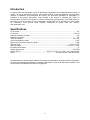
Introduction
This manual is provided by Powermatic covering the safe operation and maintenance procedures for a
Model 701 Deluxe Bench-top Mortiser. This manual contains instructions on installation, safety
precautions, general operating procedures, maintenance instructions and parts breakdown. This machine
has been designed and constructed to provide consistent, long-term operation if used in accordance with
instructions set forth in this manual. If there are any questions or comments, please contact either your
local supplier or Powermatic. Powermatic can also be reached at our web site: www.powermatic.com.
Specifications
Model No. .................................................................................................................................................. 701
Stock No. ........................................................................................................................................... 1791310
Chisel shank capacity, maximum .............................................................................................................. 3/4"
Chuck capacity, maximum ........................................................................................................................ 1/2"
Chisel stroke, maximum ......................................................................................................................... 5-1/2"
Chisel center to fence distance .............................................................................................................. 4-3/8"
Bushing sizes provided .....................................................................................................................5/8", 3/4"
Fence size .............................................................................................................................. 12-1/2" x 2-5/8"
Base size ............................................................................................................................ 16-5/16" x 13-3/4"
Capacity under hold-down ........................................................................................................................... 5"
Spindle speed ................................................................................................................................ 1725 RPM
Motor (TEFC) .......................................................................... 3/4 HP, 1 PH, 4P, 115V/230, Pre-wired 115V
Weight (net/shipping) ....................................................................................................................... 84 / 92 lb
The above specifications were current at the time this manual was published, but because of our policy of
continuous improvement, Powermatic reserves the right to change specifications at any time and without
prior notice, without incurring obligations.

Unpacking
Remove contents from the shipping carton. Check
for damage and ensure all parts are intact. Any
damage should be reported immediately to your
distributor and shipping agent. Read the manual
thoroughly to familiarize yourself with the correct
assembly and maintenance procedures and proper
safety precautions.
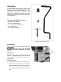
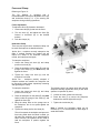
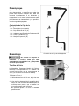
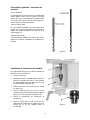
Contents of the Mortiser Carton
1 ea – Mortiser (not shown)
1 ea – 3/4" Chisel Bushing (A)
1 ea – Chuck Extension Adaptor (B)
1 ea – Chuck Key (C)
1 ea – Operating Handle (D)
Assembly
Do not connect the machine to
power source until completely
assembled. Read and understand the entire
manual.
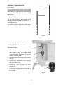
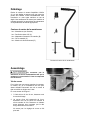
Gib Screws
The Powermatic Model 701 Deluxe Bench-top
Mortiser is packaged with the head locked to
prevent movement during shipment and is in the
down position.
Referring to Figure 1:
1. Using a 10mm wrench loosen three lock nuts.
2. With a 3mm hex wrench loosen three gib
screws the same amount. Loosen enough to
permit the head to move freely on the column.
Do not tighten. The gib adjustment will be done
later.
Contents of the Mortiser Carton
Figure 1

8
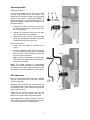
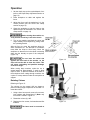
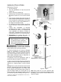
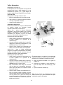
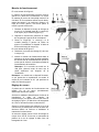
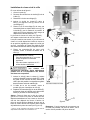
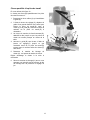
Operating Handle
Referring to Figure 2:
The operating handle can be mounted on either
the left- or right-hand side of the mortiser. The
handle hub (D) comes mounted on the right-hand
side from the factory. If right-hand operation is
desired skip steps 1–3 and proceed to step 4. For
left-hand operation the hub must be moved to the
left side as follows:
1. Unscrew and remove the hub lock knob (A),
flat washer (B), spring (C) and hub (D) from
the pinion shaft (E).
2. Remove the protective sleeve from the gear
shaft on the left side of the mortiser.
3. Install the hub (D), spring (C) and flat washer
(B) on the left-side pinion shaft and secure the
assembly with the hub lock knob (A).
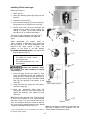
Referring to Figure 3:
4. Loosen the lock handle (F) located on the
hub (H).
5. Insert the operating handle into the bracket on
the hub. Position the upper part of the handle
away from the mortiser allowing it to clear the
switch box during operation.
Note: If handle is mounted on the right side,
also position the handle so the upper portion is
away from the mortiser
Note: The handle assembly is spring-loaded
permitting the operating handle to be repositioned
by pulling out the hub (H) and repositioning it in 36º
increments (ten positions total) on the pinion shaft.
Gib Adjustment
Now that the operating handle has been installed,
the gib screws that were previously loosened
should be adjusted.
Alternately raise and lower the mortiser head with
the operating handle, then adjust each of the three
set screws (Figure 1) with a 3mm hex wrench the
same number of turns.
Tighten the set screws to remove play from the
column but do not over tighten such that it is
difficult to raise and lower the operating handle.
When adjustment is complete, tighten the lock nut
with a 10mm wrench while maintaining the position
of the setscrew with the 3 mm hex wrench.
Figure 2
Figure 3

9
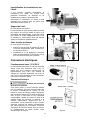
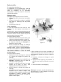
Overview – Chuck Extension
Do you need it
The 701 Mortiser comes with the chuck already
assembled at the factory, intended to be used with
augers having long shanks. Augers come with long
or short shanks (Figure 4) depending on the
manufacturer.
Long shank augers
If you plan to install an auger with a long shank,
you can skip this section and proceed to the
Installing Chisel and Auger section on page 10.
Short shank augers
If you plan to install an auger with a short shank,
proceed to Installing the Chuck Extension section.
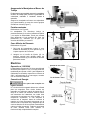
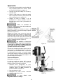
Installing the Chuck Extension
Referring to Figure 4, remove the chuck from the
motor shaft as follows:
1. Open door (A).
2. Unscrew and remove the chuck (B) from the
motor shaft (C) using a 12mm wrench placed
on the flat indents of the shaft (C) and the
chuck key in the chuck (B).
3. Thread the chuck extension (D) onto the motor
shaft (C).
4. Tighten using 12mm and 14mm wrenches
respectively on flat sides of the motor shaft (C)
and chuck extension (D).
5. Thread the chuck (B) onto the chuck
extension (D).
6. Tighten using a 14mm wrench on flat sides of
the chuck extension (D) and the chuck key in
the chuck (B).
Figure 4
Figure 5

10
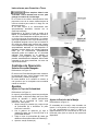
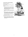
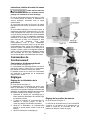
Installing Chisel and Auger
Referring to Figure 6:
1. Open door (A).
2. Swing two bushing spacers (B) away from the
head (C).
3. Loosen the lock screw (D).
4. Insert the chisel bushing* (E) into the head (C),
lining up the hole (F) with the lock screw (D).
5. Set the lock screw (D) so the threaded end
extends into the hole (F) of the bushing (E),
holding it in place. The bushing should still
have about 1/4" of vertical travel margin.
The chisel to auger clearance (see Figure 6) is
the vertical c
learance between the auger and
chisel.
When assembled, the proper chisel to
auger clearance is dependant on the chisel size
and the position of the chisel (adjustable) with
respect to the auger (which is fixed). The
position of the chisel is set with spacers
described in the following steps.
6. Position spacers (B) so they rest against the
bushing above the lip (J).
Number of spacers to use:
For chisels 1/2" or less – use the
upper spacer only
For chisels greater than 1/2" – use
both spacers
Chisels are extremely sharp.
Use extreme care when handling to prevent
personal injury.
7. Insert the auger (K) into the chisel (L). Then
insert the assembly through the bushing (E).
Using gloves or a block of wood, press up on
the auger as far as it will go. The shank should
slide into the opening in the bottom of the
chuck (M).
8. Using the chuck key, tighten the chuck (M) to
secure the auger (K).
9. Move the spacers (B) away from the
bushing (E), push the chisel and bushing up
against the head (C); then tighten the lock
screw (D).
Hint: Set the s
lot in the side of the chisel to the left
or right if the workpiece is to be moved laterally
and front or back if it is to be moved from front to
back. The workpiece should be moved so that the
slot in the chisel is releasing chips into the already
cut part of the workpiece (see Figure 14).
* Only if changing bushings. The 701 Mortiser comes with the
5/8" bushing already installed.
Figure 6
Note: This would be a good time to make sure that
the chisel is parallel to the workpiece. See the
Chisel Parallel to Workpiece section.

11
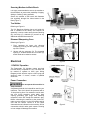
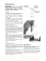
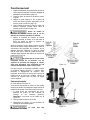
Securing Mortiser to Work Bench
It is highly recommended to secure the mortiser to
the workbench to prevent the possibility of tipping,
sliding or "walking" during operation.
Secure the mortiser to the bench with fasteners
(not supplied) through four holes located in the
base (Figure 7).
Tool Holder
Referring to Figure 8:
The 701 Bench-top Mortiser has a tool holder (A)
that is installed at the factory and requires no
assembly. It can be used to store the extra bushing
(B), chuck key (C), extension (D) as well as any
additional chisels and accessories.
Diamond Sharpening Cone
Referring to Figure 8:
1. From hardware kit insert the diamond
sharpening cone (E) into the opening (F) at the
top of the column.
2. Secure with the setscrew (G). The threaded
opening is located behind the tool holder (A)
which needs to be raised to access.
Electrical
115V/230V Operation
The Powermatic 701 Mortiser comes pre-wired
from the factory to operate at 115V. The motor can
be rewired to operate at 230V (see Wiring
Diagram) which will also require a 230V plug and
electrical outlet. If unsure, consult a qualified
electrician.
Power Connection
Do not operate this machine in
damp locations.
A separate electrical circuit should be used for your
machines. This circuit should be protected with a
15 Amp time lag fuse. If an extension cord is used,
use only 3-wire extension cords which have
3-prong grounding type plugs and matching
receptacle, which will accept the machine’s plug.
Before connecting the machine to the power line,
make sure the switch is in the Off position and be
sure that the electric current is of the same
characteristics as indicated on the machine. All line
connections should make good contact. Running
on low voltage will damage the machine.
Figure 7
Figure 8
Figure 9

12
Grounding Instructions
This machine must be
grounded while in use to protect the user from
shock
In the event of a malfunction or breakdown,
grounding provides a path of least resistance for
electric current to reduce the risk of electric shock.
If you are not sure whether your outlet is properly
grounded, consult a qualified electrician.
Referring to Figure 9: As received from the factory,
your mortiser is ready to run at 115-volt operation.
This mortiser is intended for use on a circuit that
has an outlet and a plug that looks like the one
illustrated in (A). A temporary adaptor, which looks
like the adaptor shown in (B), may be used to
connect this plug to a two-pole receptacle if a
properly grounded outlet is not available. The
temporary adaptor should only be used until a
properly grounded outlet can be installed by a
qualified electrician. This adaptor is not applicable
in Canada. The green colored rigid ear, lug, or tab,
extending from the adaptor, must be connected to
a permanent ground such as a properly grounded
outlet box.
Operating Controls
Start/Stop Switch
Referring to Figure 10:
The Start/Stop switch is located to the left of the
motor. Flip the switch out to start; flip in to stop.
The yellow insert is a switch lock which prevents
the mortiser from being started when removed.
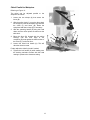
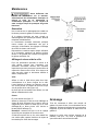
Adjustments
Depth Stop Adjustment
Referring to Figure 11:
A depth stop is provided to limit the depth, or
downward travel, of the chisel. This enables the
operator to make repeated boring operations
without the need to measure each bore. To adjust:
1. Loosen the lock handle (A) and bring the depth
stop (B) to rest at the bottom of the column.
2. With the operating handle (C) lower the
head (D) until the chisel (E) is at the desired
depth.
3. Bring the depth stop (B) up until it comes to
rest against the bottom of the head (D).
4. Tighten the lock handle (A).
Figure 10
Figure 11
Handle Position Adjustment
Referring to Figure 11:
The handle assembly is spring-loaded permitting
the operating handle (C) to be repositioned by
pulling out the hub (F) and repositioning it (G) in
36º increments on the pinion shaft for a total of ten
available positions.

13
Chisel Parallel to Workpiece
Referring to Figure 12:
The chisel can be adjusted parallel to the
workpiece as follows:
1. Loosen the two clamps (A) that secure the
fence (B).
2. With the adjust knob (C), move the fence back
far enough to insert the workpiece (D) between
the chisel (F) and fence (B). Raise the
workpiece hold-down clamp (E) if necessary.
3. With the operating handle (G) bring the head
down until the chisel points are almost at the
table level.
4. Bring the fence (B) forward with the adjust
knob (C) until the front edge of the
workpiece (D) rests against the back surface of
the chisel (F), but do not force.
5. Loosen the chisel lock handle (H). This will
allow the chisel to rotate.
Further adjust the chisel by hand if needed.
6. Tighten the lock handle (H) while making sure
the bushing maintains contact with the head
casting to preserve the clearance setting.
Figure 12

14
Fence and Clamp
Referring to Figure 13:
The 701 Mortiser is equipped with a
forward/backward movement adjustable fence (B)
and hold-down clamp (F, K, L) for securing the
workpiece during mortising operations.
Fence Adjustment
To adjust the fence (B) forward or backward:
1. Loosen two clamps (A) that lock the fence.
2. Turn the knob (C) and adjust the fence (B)
forward or backward (D) to the desired
position.
3. Lock the clamps (A).
Hold-down Clamp
There are two ways that the hold-down clamp can
be used. Both options are described below.
Option One – workpiece securely clamped to the
table. If multiple mortises are needed, this will
require the clamp to be loosened, workpiece
moved, and clamp secured again.
To clamp the workpiece:
1. Loosen the clamp lock knob (H) and clamp
position lock knob (G).
2. Place the workpiece on the table (E) under the
prongs of the clamp (F) (see Note below) and
against the fence.
3. Tighten the clamp lock knob (H) until the
workpiece is secured.
Option two – workpiece partially clamped. If
multiple mortises are needed, the workpiece can
be moved by hand without repetitively loosening
and tightening the clamp.
To clamp the workpiece:
1. Loosen the clamp lock knob (H) and clamp
position lock knob (G).
2. Place the workpiece on the table (E) (see Note
below) under the prongs of the clamp (F) and
against the fence (B).
3. Bring the clamp down so the prongs rest on
the workpiece, but do not press against the
workpiece.
4. Tighten the clamp position lock knob (G).
This will constrain the workpiece and prevent it
from being lifted when the chisel is raised, yet
still allow the workpiece to be repositioned by
hand. However, the operator will still need to
hold the workpiece in position against the
fence.
Figure 13
The following step is an option which will hold the
workpiece securely against the fence yet still allow
operator to reposition by hand.
5. Loosen the roller guides lock knobs (K).
6. Press the tabs (L) to secure the workpiece
between the wheels (M) and fence (B).
7. Tighten the lock knobs (K).
Note: If needed, the hold-down clamp can be
reversed (K, L) to accommodate a wide range of
wood thicknesses.

15
Operation
1. Set the depth stop to the required depth of cut
(refer to the Depth Stop Adjustment section on
page 12).
2. Place workpiece on table and against the
fence.
3. Adjust the fence until the workpiece is in the
correct position (see the Fence and Clamp
section on page 14).
4. Clamp the workpiece or set the clamp to the
desired height as described in the Fence and
Clamp section on page 14)
Before turning the machine on,
verify that the chuck key is not in the chuck.
5. Turn on the machine and feed the chisel and
auger steadily into workpiece by pulling down
the operating handle.
After the first cut, move the workpiece along for
each successive cut. The direction of movement
must allow the chips to clear freely. Move the
workpiece so that the slot in the chisel is releasing
chips into the already cut part of the workpiece
(Figure 14).
Do not have the chisel slot
against the blind end of the mortise, as the
chips will not be able to clear the chisel. This
can cause overheating and possible breakage
of chisel or auger.
When cutting deep mortises, make the cut in
several stages of approximately 1" each, to allow
chips to clear. To prevent breakout at the back of
the workpiece when cutting through mortises, use
a piece of scrap material under the workpiece as
support.
Rotating Column
Referring to Figure 15:
The column can be rotated 180º as shown to
permit mortising large workpieces off the table. To
rotate the column:
1. Using a 4mm hex wrench, remove four screws,
lock washers and flat washers (C) Note: only
one screw is visible in Figure 15.
2. Rotate the column (A) 180º.
3. Replace the four screws, lock washers and flat
washers.
The base must be secured to
the work bench.
Figure 14
Figure 15

16
Maintenance
Before any intervention on the
machine, disconnect it from the electrical
supply by pulling out the plug or switching off
the main switch! Failure to comply may cause
serious injury.
General
A coat of paste wax applied to the table and
column will help to keep the surfaces clean.
If the power cord is worn, cut, or damaged in any
way, have it replaced immediately.
The Mortiser requires only minor maintenance,
such as cleaning and lubrication and routine
adjustment and sharpening of the chisel and
auger.
Dust the machine down after each use and, as
necessary, use light applications of oil or grease to
lubricate linkages, moving parts, etc.
Sharpening Chisel and Auger
The chisel and auger should be kept sharp for best
performance. Blunt edges will give inaccurate
mortises and can lead to overheating and
breakage to chisel or auger. If chisel and auger are
badly worn and become difficult to sharpen, they
should be replaced.
Auger
Sharpen the auger by using a small, smooth file,
following the original shape of the auger. File the
inside edge of the spur, the sides of the brad point,
and the cutting edge inwards toward the flute of
the auger (Figure 16).
Do not file the outside edge of the spur, as this will
affect the diameter of the auger.
Chisel
Referring to Figure 17:
Sharpen the chisel (A) with the chisel sharpening
cone (B) located on the top of the column next to
the tool holder. Set the chisel (A) on the
sharpening cone (B) and rotate back and forth until
sharpened (C).
Note: Make sure the set-screw is tight to prevent
the cone from spinning.
Using a fine stone or micro-abrasive on a flat
surface, lap the outside faces of the mortise bit to
remove any burrs.
Figure 16
Figure 17
Lubrication
All of the ball bearings are packed with grease at
the factory. They require no further lubrication.
Periodically grease the gears, racks, and table
pivot points with a #2 tube grease.
Periodically clean and oil any exposed machine
surfaces, such as: dove-tail ways and slides, and
table surface.
Storage
If the mortiser will be stored for an extended
period, use the depth stop to help secure the head
in position; this will relieve stress upon the
hydraulic cylinder.

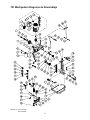
17
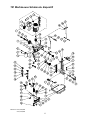
701 Mortiser Assembly Drawing
Patent No. US 7,509,984
US 7,243,692

18
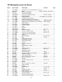
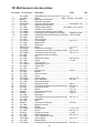
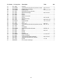
701 Mortiser Parts List
Index No. Part No. Description Size Qty
1 ............... 701-164MA .............. Motor Assembly (includes #1.1 thru 1.10) ........... .................................... 1
1.1 ............ 701-164M ................. Motor……………………………………..3/4HP, 115/230V, 1PH, 60HZ ..... 1
1.2 ............ 994534 ..................... Switch ................................................................... .................................... 1
1.3 ............ 701-165B ................. Switch Box ........................................................... .................................... 1
1.4 ............ TS-081C052 ............. Phillips Pan Hd Machine Screw ........................... #10-24UNC x 3/4L ..... 2
1.5 ............ 701-167B ................. Strain Relief.......................................................... .................................... 1
1.6 ............ 701-168B ................. Power Cord………………………………….SJT16AWG x 3C x 210CM .... 1
1.7 ............ 701-164AB ............... Fan (not shown) ................................................... .................................... 1
1.8 ............ 701-164BB ............... Fan Cover (not shown) ........................................ .................................... 1
1.9 ............ 701-164CB ............... Starting Capacitor (not shown) ............................ 200MFD 125VAC ........ 1
1.10 .......... 701-164DB ............... Running Capacitor (not shown) ........................... 30mF 250VAC ............ 1
2 ............... 701-102B ................. Shaft Cap ............................................................. .................................... 1
3 ............... 701-161B ................. Pinion Shaft .......................................................... .................................... 1
4 ............... TS-1523011 ............. Socket Hd Set Screw ........................................... M6-1.0 x 6L ................ 1
5 ............... 701-159B ................. Collar .................................................................... .................................... 1
6 ............... 701-158B ................. Gear ..................................................................... .................................... 1
7 ............... WP2510-215 ............ Key, Dbl Rd Hd .................................................... 5 x 5 x 12L .................. 2
8 ............... TS-1551041 ............. Lock Washer ........................................................ M6 ............................... 7
9 ............... TS-1503051 ............. Socket Hd Cap Screw .......................................... M6-1.0 x 20L ............... 3
10 ............. TS-1534042 ............. Phillips Pan Hd Machine Screw ........................... M6-1.0 x 12L ............... 2
12 ............. 701-162B ................. Chuck Access Cover ............................................ .................................... 1
13 ............. 701-156B ................. Head ..................................................................... .................................... 1
14 ............. 701-172B ................. Locking Handle .................................................... M8-1.25 x 30L ............. 1
15 ............. 701-176B ................. Bushing ................................................................ I.D. 5/8 IN .................... 1
18 ............. 701-170B ................. Chuck with key ..................................................... .................................... 1
................. 701-143NCA ............ Cylinder Assembly ............................................... .................................... 1
19 ............. 701-144N ................. Cylinder Fitting ..................................................... .................................... 2
20 ............. 701-143N ................. Cylinder ................................................................ .................................... 1
21 ............. 6012290 ................... E-Retaining Ring .................................................. ETW-7 ......................... 2
22 ............. 701-153B ................. Handle .................................................................. .................................... 1
23 ............. 701-155B ................. Handle Grip .......................................................... .................................... 1
24 ............. 701-150B ................. Gib ........................................................................ .................................... 1
25 ............. TS-1523071 ............. Soc Hd Set Screw ................................................ M6 -1.0 x 25L .............. 3
26 ............. TS-1540041 ............. Hex Nut ................................................................ M6-1.0P ...................... 3
27 ............. 701-173B ................. Bushing Spacer ....
................................................ .................................... 2
28 ............. F011901 ................... Wave Washer....................................................... WW-5 .......................... 1
29 ............. F005365L ................. Socket Hd Cap Screw w/thrdlckr ......................... M5-0.8 x 16L ............... 1
30 ............. F012100 ................... Roll Pin ................................................................. 4 x 25L ........................ 4
31 ............. 701-130B ................. Knob ..................................................................... 16 x 15L ...................... 2
32 ............. F006044 ................... C-Retaining Ring Ext. .......................................... STW-16 ....................... 2
33 ............. F006091 ................... E-Retaining Ring .................................................. ETW-12 ....................... 2
34 ............. 701-125B ................. Gear ..................................................................... .................................... 1
35 ............. TS-1503031 ............. Socket Hd Cap Screw .......................................... M6-1.0 x 12L ............... 2
36 ............. 701-141B ................. Rack ..................................................................... .................................... 1
37 ............. 701-126B ................. Shaft ..................................................................... .................................... 1
38 ............. F006047 ................... C-Retaining Ring Ext. .......................................... STW-20 ....................... 1
39 ............. 701-149B ................. Handle Hub .......................................................... .................................... 1
40 ............. 23011063 ................. Spring ................................................................... .................................... 1
41 ............. TS-1550041 ............. Flat Washer .......................................................... 6 x 19 x 1.6T ............... 1
42 ............. 701-146B ................. Knob ..................................................................... M6-1.0 x 10L ............... 1
43 ............. F012078 ................... Roll Pin ................................................................. 6 x 20L ........................ 1
44 ............. 701-154B ................. Lock Handle ......................................................... M6-1.0 x 12L ............... 1
45 ............. 701-180B ................. Chisel Sharpening Cone ...................................... .................................... 1
46 ............. TS-2276081 ............. Socket Hd Set Screw ........................................... M6-1.0 x 8L ................. 2
49 ............. 701-139B ................. Tool Tray .............................................................. .................................... 1
50 ............. TS-1502031 ............. Socket Hd Cap Screw .......................................... M5-0.8 x 12L ............... 2

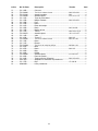
19
Index No. Part No. Description Size Qty
51 ............. 701-136B ................. Column ................................................................. .................................... 1
52 ............. TS-1504061 ............. Socket Hd Cap Screw .......................................... M8-1.25 x 30L ............. 4
53 ............. TS-1551061 ............. Lock Washer ........................................................ M8 ............................... 4
54 ............. TS-1550061 ............. Flat Washer .......................................................... 8.5 x 16 x 1.5T ............ 5
55 ............. 701-131B ................. Depth Stop ........................................................... .................................... 1
57 ............. 701-133B ................. Locking Handle .................................................... M8-1.25 x 65L ............. 1
58 ............. 701-120B ................. Post ...................................................................... .................................... 1
59 ............. 701-123B ................. Knob ..................................................................... .................................... 1
60 ............. 701-121B ................. Work Hold-Down .................................................. .................................... 1
61 ............. 701-122B ................. Knob ..................................................................... M6-1.0x 23L ................ 1
62 ............. 701-119B ................. Cam Handle ......................................................... .................................... 2
63 ............. 701-117B ................. Bolt ....................................................................... M8-1.25 x 15.5L .......... 2
64 ............. TS-1550071 ............. Flat Washer .......................................................... 10.2 x 23 x 2T ............. 2
65 ............. 701-114B ................. Fence ................................................................... .................................... 1
67 ............. 701-103B ................. T-Nut .................................................................... M8-1.25 ....................... 2
68 ............. TS-1503041 ............. Socket Hd Cap Screw .......................................... M6-1.0 x 16L ............... 2
69 ............. 701-112B ................. Bar ........................................................................ .................................... 1
70 ............. 701-111B ................. Rack ..................................................................... .................................... 1
71 ............. TS-1533042 ............. Phillips Pan Hd Machine Screw ........................... M5-0.8 x 12L ............... 2
72 ............. 701-101B ................. Base ..................................................................... .................................... 1
73 ............. 701-107B ................. Knob ..................................................................... M8-1.25 ....................... 2
74 ............. 701-106B ................. Bushing ................................................................ .................................... 2
75 ............. 701-108B ................. Roller .................................................................... .................................... 2
76 ............. TS-1550061 ............. Flat Washer .......................................................... 8.2 x 23 x 2T ............... 2
77 ............. 701-105B ................. Slide Plate ............................................................ .................................... 2
78 ............. 701-104B ................. Hex Cap Screw (Special) ..................................... M8-1.25 x 45L ............. 2
79 ............. 23011020 ................. Chuck Extension Adapter .................................... .................................... 1
80 ............. 701-177B ................. Bushing ................................................................ I.D. 3/4 IN .................... 1
81 ............. 6294204B ................. Chuck Key ............................................................ .................................... 1

20
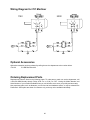
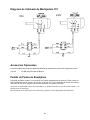
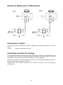
Wiring Diagram for 701 Mortiser
115V
230V
Optional Accessories
Optional accessories can be purchased by calling the service department at the number below.
1791312 701-RB Riser Block Kit
Ordering Replacement Parts
Replacement parts are listed on the following pages. To order parts or reach our service department, call
1-800-274-6848 Monday through Friday, 8:00 a.m. to 5:00 p.m. CST. Having the Model Number and
Serial Number of your machine available when you call will allow us to serve you quickly and accurately.
Non-proprietary parts, such as fasteners, can be found at local hardware stores, or may be ordered from
Powermatic. Some parts are shown for reference only, and may not be available individually.
La page est en cours de chargement...
La page est en cours de chargement...
La page est en cours de chargement...
La page est en cours de chargement...
La page est en cours de chargement...
La page est en cours de chargement...
La page est en cours de chargement...
La page est en cours de chargement...
La page est en cours de chargement...
La page est en cours de chargement...
La page est en cours de chargement...
La page est en cours de chargement...
La page est en cours de chargement...
La page est en cours de chargement...
La page est en cours de chargement...
La page est en cours de chargement...
La page est en cours de chargement...
La page est en cours de chargement...
La page est en cours de chargement...
La page est en cours de chargement...
La page est en cours de chargement...
La page est en cours de chargement...
La page est en cours de chargement...
La page est en cours de chargement...
La page est en cours de chargement...
La page est en cours de chargement...
La page est en cours de chargement...
La page est en cours de chargement...
La page est en cours de chargement...
La page est en cours de chargement...
La page est en cours de chargement...
La page est en cours de chargement...
La page est en cours de chargement...
La page est en cours de chargement...
La page est en cours de chargement...
La page est en cours de chargement...
La page est en cours de chargement...
La page est en cours de chargement...
La page est en cours de chargement...
La page est en cours de chargement...
La page est en cours de chargement...
La page est en cours de chargement...
La page est en cours de chargement...
La page est en cours de chargement...
La page est en cours de chargement...
La page est en cours de chargement...
La page est en cours de chargement...
La page est en cours de chargement...
La page est en cours de chargement...
La page est en cours de chargement...
La page est en cours de chargement...
La page est en cours de chargement...
-
 1
1
-
 2
2
-
 3
3
-
 4
4
-
 5
5
-
 6
6
-
 7
7
-
 8
8
-
 9
9
-
 10
10
-
 11
11
-
 12
12
-
 13
13
-
 14
14
-
 15
15
-
 16
16
-
 17
17
-
 18
18
-
 19
19
-
 20
20
-
 21
21
-
 22
22
-
 23
23
-
 24
24
-
 25
25
-
 26
26
-
 27
27
-
 28
28
-
 29
29
-
 30
30
-
 31
31
-
 32
32
-
 33
33
-
 34
34
-
 35
35
-
 36
36
-
 37
37
-
 38
38
-
 39
39
-
 40
40
-
 41
41
-
 42
42
-
 43
43
-
 44
44
-
 45
45
-
 46
46
-
 47
47
-
 48
48
-
 49
49
-
 50
50
-
 51
51
-
 52
52
-
 53
53
-
 54
54
-
 55
55
-
 56
56
-
 57
57
-
 58
58
-
 59
59
-
 60
60
-
 61
61
-
 62
62
-
 63
63
-
 64
64
-
 65
65
-
 66
66
-
 67
67
-
 68
68
-
 69
69
-
 70
70
-
 71
71
-
 72
72


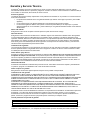
Powermatic PM701 Benchtop Mortiser 3/4HP 1PH 115/230V 1791310 Manuel utilisateur
- Taper
- Manuel utilisateur
- Ce manuel convient également à
dans d''autres langues
Documents connexes
-
Powermatic 1791310 Mode d'emploi
-
-
Powermatic 31A Mode d'emploi
-
-
-
Powermatic PJ-882 Manuel utilisateur
-
-
Autres documents
-
Porter-Cable 513 Manuel utilisateur
-
-
Delta 14-651 Manuel utilisateur
-
Powerfist 9027939 Le manuel du propriétaire
-
-
Delta 14-651 Le manuel du propriétaire
-
Craftsman 113.213170 Le manuel du propriétaire
-
 Drill Doctor XP2 Manuel utilisateur
-
 Drill Doctor XP Manuel utilisateur
-
JET JBM-5 Manuel utilisateur

