UPM THM101B Le manuel du propriétaire
- Catégorie
- Thermostats
- Taper
- Le manuel du propriétaire

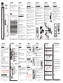
THERMOSTAT
THM101B
OWNER’S
MANUAL
FEATURES
Read and understand this
manual before installation or
use.
• Easy-to-read LCD display
• Easy-to-set temperature
settings
• Heat–OFF–Cool and fan
auto-on switch
This thermostat can replace common residential thermostats and it is
designed for use with most electric, oil or gas heating and air conditioning
systems that use low voltage control.
Note: 2 x “AA” batteries are required for operation. Ensure batteries are installed.
INSTALLATION
PAGE 1 PAGE 2 PAGE 3 PAGE 4 PAGE 5
PAGE 6 PAGE 7
PAGE 8 PAGE 9 PAGE 10
FAN
ON AUTO
COOL
OFF
HEAT
COOL
ON
Approximately 5’ (1.5 m) from the floor.
This thermostat should be mounted:
CHOOSING A LOCATION FOR A NEW THERMOSTAT
Near or in a frequently occupied room, preferably on an inside partitioning wall.
On a section of the wall without pipes or duct-work.
Near a window, on an outside wall, or next to a door leading outside.
This thermostat should NOT be mounted:
Exposed to direct light or heat from the sun, lamp, fireplace, or other heat radiating
objects which may cause false readings.
Near or in a direct airflow from supply registers and return-air grilles.
Near concealed pipes and chimneys.
In areas of poor air circulation, such as behind a door or in an alcove.
System Type
Gas - Standing Pilot
Gas - Electronic Ignition
Gas - Fire Boiler
Gas - Millivolt System
Oil - Fire Boiler
Oil - Fire Furnace
Electric Furnace
Electric Air Conditioner
Baseboard Electric Heater (120/240 V)
Heat Pump/Multi-stage equipment
Compatible with thermostat
Yes
Yes
Yes
Yes
Yes
Some models
Some models
No
No
Yes
COMPATIBILITY
Generally, equipment with low voltage control is compatible with the thermostat. For details
on compatibility of your particular equipment, please call technical support at 1-888-468-6876.
* NOT COMPATIBLE WITH ANY 120/240 V CIRCUIT.
INSTALLATION
The following tools may be required for installation:
( ) screwdriver
Masking tape (To wrap the exposed wires temporarily and labeling the disconnected wires)
Wire stripper/cutter (If necessary, to strip wires)
Power drill with a 3/16” bit (If necessary, to drill holes on the wall)
Level (If necessary, to level the thermostat)
INSTALLATION
REPLACING OLD THERMOSTAT
TURN OFF POWER to system at the furnace, or at the fuse/circuit breaker panel.
Carefully unpack your new thermostat and mounting plate; save package of screws,
instructions and receipt.
Remove cover from old thermostat. If it does not snap off when pulled firmly from the
bottom, check for a screw used to secure the cover.
Loosen screws holding thermostat to the wall and lift away the thermostat.
Disconnect wires from old thermostat or sub-base. As you disconnect each wire, use
masking tape to label it with the old terminal designation. If there are only two wires,
they don't need to be labeled.
If there is an extra wire that is not connected to your old thermostat, then you won't
need to connect it to the new thermostat.
After choosing a location for the new thermostat, you may arrange to have a
heating contractor install the control wiring for you.
Do not operate the cooling system when outside temperature is below 10
(50 ) to avoid damaging the compressor.
°C
°F
*
Test the system to make sure that your heating and cooling systems are working
properly before installation. If either does not work, contact a local heating/air
conditioning service person to fix the problem before installation.
Take care not to let the wires fall back into the wall or let the ends of the wires touch
one another.
The wires are usually designated 'W', 'Y', 'G', 'R’
INSTALLATION
MOUNTING THE THERMOSTAT BACK COVER
The back cover should be mounted with the large hole on the top.
Thread the existing wiring through the large hole from the back and set the back
cover flat on the wall.
Select two appropriate mounting holes and mark the locations with a pencil. If
necessary, use a level to make sure the thermostat is leveled.
Remove the back cover from the wall and drill two 3/16” holes in the marked screw
positions.
Insert the wall anchors into the holes completely. If necessary, use a hammer to
tap-in lightly.
Mount the back cover, with the two screws, to the wall. Make sure the terminals are
on the top-half of the back cover.
Carefully separate the back cover from the thermostat by disengaging the 4 latches
found at the corners on the back of the thermostat. Pull firmly but DO NOT try to pry
open with a screwdriver.
INSTALLATION
CONNECTING THE WIRES TO THE TERMINALS
Depending on your heating/cooling equipment, you may
need to connect 2 to 5 wires to the thermostat.
If your old thermostat has a ‘C’ wire, please wrap it with
electrician’s tape as it is not used with this thermostat.
If you have both an ‘R’ and ‘Rc’ wire, you may connect
them together to the ‘R’ terminal of the thermostat.
If you are unsure of the connections, or for new
installation, you may refer to the wiring diagrams below.
Connect the previously labeled wires to the corresponding terminals, matching the
designations. Use a screwdriver to securely fasten the wires onto the terminals. Make sure
the wires do not short-circuit with other terminals.
Cooling Relay
Fan Relay
Heating Relay
WIRING DIAGRAM
Heating Relay
Heating Relay
Fan Relay
2-wire heating
4-wire heating/cooling
3-wire heating
INSTALLATION
SETTING THE FAN OPERATION JUMPER
Depending on your home’s heating system, you may need to change the jumper setting for
the fan operation. The jumper is located above the battery compartment.
HG - Use this setting for gas or oil-fired furnaces. This setting allows the fan
operation to be controlled by the heating system; not the thermostat. This is the
correct setting for most systems.
HE - Use this setting for electric heating systems. With this setting, the thermostat
will turn on the fan immediately with the heating system.
The jumper is pre-installed in the ‘HG’ position as a factory default. So there is no need to
change the jumper if this is the correct setting.
To change the jumper setting, pull out the small black rectangular block and align it to the
new position and push in fully.
INSTALLATION
BATTERY INSTALLATION
2 “AA” size batteries are required for operation. The battery symbol ( ) will flash when the
batteries are low. It is recommended that the batteries be replaced at least once a year.
Remove the back cover from the thermostat.
Insert the 2 “AA” size batteries into the battery compartment following the correct
polarity as marked.
Immediately following the battery installation, the thermostat will enter the °C/°F
selection mode. The current temperature will appear with the temperature scale
(in °C) flashing.
SELECTING THE DISPLAY IN C or F°°
Re-attach the back cover.
NOTE: To select the temperature display format in °C or °F, it must be done immediately
following the battery installation.
Use the UP or DOWN button to select the desired temperature scale (in °C or °F).
Otherwise, if no buttons are pressed within 12 seconds, °C will automatically be
selected, and the thermostat will go to its operation mode.
NOTE: Selecting the °C or °F display is a one-time process. Therefore, if you wish to change
it at a later time, you will need to reset the thermostat by pressing the RESET key
above the battery compartment and select °C or °F using the UP or DOWN button.
Attach the thermostat body to the back cover (that is already installed on the wall) by
carefully aligning the two pieces and firmly snapping the 4 latches at the back of the
thermostat.
ATTACHING THE THERMOSTAT TO THE BACK COVER
TURN OFF POWER to system at the furnace, or at the fuse/circuit breaker before wiring.
DISPLAY / BUTTONS
button placement
UP BUTTON
DOWN BUTTON
FAN
ON AUTO
COOL
OFF
HEAT
COOL
ON
1
2
1
2
OPERATION
“HEAT–OFF–COOL” SWITCH
OFF position:
- If the switch is to the OFF position, both the heating and cooling system controls will be
turned OFF.
If the heating or cooling system is turned ON, the “ON” icon will appear and
continue to flash.
HEAT position:
- Slide the switch to the HEAT position to control the heating system.
- The “HEAT” icon will light up when the switch is on the HEAT position.
COOL position:
- Slide the switch to the COOL position to control the cooling system.
- The “COOL” icon will light up when the switch is on the COOL position.
FAN ON/AUTO SWITCH
For automatic control of the fan, set the FAN ON/AUTO switch to the AUTO position.
In cooling, the fan starts/stops with the cooling equipment. In heating, the fan is
controlled by the heating equipment and usually starts a few minutes after the
heating equipment turns on.
To turn on the fan manually, set the FAN ON/AUTO switch to the ON position. The fan
will run continuously to improve air ventilation. To return to automatic control, set the
switch to the AUTO position.
OPERATION
TEMPERATURE SETTING
Press the UP or DOWN button once to enter the temperature setting
mode. The “ ” icon will appear, and the display will now show the
current SET temperature flashing.
1
Press the UP or DOWN button to adjust to the desired set temperature.
NOTE: Press and hold the button
down to accelerate the setting. If no
button is pressed within 12 seconds,
the display will automatically return
to the current temperature display.
2
The temperature can be set in increments of 0.5°.
The temperature setting range is from 5°C to 35°C (41°F to 95°F).
OPERATION
CURRENT TEMPERATURE DISPLAY
The current room temperature is normally displayed
on the LCD screen. The “ ” icon is lit when the
current room temperature is displayed.
The displayed temperature range is from 0°C to 60°C
(32°F to 140°F). Beyond this, the display will show
either “HI” or “LO”.
The resolution of the detected temperature is 0.1°.
VIEWING THE SET TEMPERATURE
Pressing either the UP or DOWN button once will
reveal the current SET temperature. The “ ” icon
will appear and the current SET temperature will be
flashing.
NOTE: There is a built-in delay action to protect the heating and cooling systems.
- When the heating system is ON, it will keep on running for at least 2 minutes even if there
is a change in the temperature setting.
- When the heating system is OFF, it will remain OFF for at least 2 minutes before it can
come back ON.
- When the cooling system is ON, it will keep on running for at least 4 minutes even if there
is a change in the temperature setting.
- When the cooling system is OFF, it will remain OFF for at least 4 minutes before it can
come back ON.
DISPLAY AUTO-RETURN
In any setting mode, if no button is pressed within 12
seconds, the display will automatically return to the
current temperature display.
TROUBLESHOOTING
LIMITED ONE-YEAR WARRANTY
Disengage the latches to
separate the back cover
from the thermostat
LEVEL
+
+
Mark the locations
with a pencil
Metal terminals
Back cover
Wall
Back cover
Metal
terminals
Wires
HEAT
HEAT
HEAT
PROBLEM SOLUTION
“HEAT–OFF–COOL” SWITCH
3
FAN ON/AUTO SWITCH
4
4 3
PAGE 11 PAGE 12 PAGE 13 PAGE 14
H
GH
G
HEHE
H
G
H
G
H
E
H
E
LCD screen is blank.
The battery symbol ( ) is
flashing.
Heat will not come on.
Heat will not come on but the
“ON” icon is flashing.
Air conditioning will not come on.
Air conditioning will not come on
but the “ON” icon is flashing.
- Check if the batteries are installed correctly.
- Check if the batteries are fresh and of the correct type.
- Press the RESET key on the back of the thermostat above the battery compartment.
- This is an indication that the batteries are running low. Replace with fresh alkaline
batteries.
- Note: We recommend to have the batteries replaced at least once a year even if the battery
symbol is not flashing.
1) Check and ensure that the thermostat is set to the HEAT mode.
2) Check and ensure that the set temperature is higher than the current (room) temperature.
3) You may have to wait up to 2 minutes before the heat will turn on. The thermostat has a
built-in time delay to prevent undesirable on/off sequences.
4) After a 2-minute wait, the heating should now be on. Whenever the heating system is
running, the “ON” icon will be flashing.
1) Check if the furnace switch and/or pilot flame is turned on, as it may have been turned off.
2) Allow several minutes for the heating system to heat up and the fan to activate. Most
heaters will heat up the system for a short while before warm air can be ventilated by the
fan. Also check that the HE/HG setting is set correctly. (Refer to page 7).
3) If the heat still does not come on, check the wiring installation again. (Refer to page 6).
1) Check and ensure that the thermostat is set to the COOL mode.
2) Check and ensure that the set temperature is lower than the current (room) temperature.
3) You may have to wait up to 5 minutes before the air conditioning will turn on. The
thermostat has a built-in time delay to protect the air conditioner compressor from
undesirable on/off sequences.
4) After a 5-minute wait, the air conditioning should now be on. Whenever the cooling
system is running, the “ON” icon will be flashing.
1) Check if the air conditioning system’s main switch is turned on, as it may have been
turned off.
2) Wait several minutes for the air conditioning system to activate. If the air conditioning still
does not come on, check the wiring installation again. (Refer to page 6).
RESET
If the thermostat shows an abnormal display or if you
wish to change the temperature scale (°C or °F), use a
pointed object to press the RESET key.
H
G
H
G
H
E
H
E
RESET
UPM warrants this product, excluding battery, to be free from defects in the materials or workmanship, under normal use and
service, for a period of one year from the date of purchase by the consumer.
If, at any time during the warranty period, the product is defective or malfunctions, UPM shall repair or replace it (at UPM's
discretion) within a reasonable period of time.
If the product is defective,
(i) return it, with a dated proof of purchase, to the retailer from which you purchased it, or
(ii) package it carefully, along with a dated proof of purchase and a short description of the malfunction, and mail it, postage
prepaid, to the following address:
UPM Marketing Inc.
Return Goods
Unit 10B - 250 Shields Court
Markham, Ontario
L3R 9W7
This warranty does not cover removal or reinstallation costs. This warranty shall not apply if it is shown by UPM that the defect or
malfunction was caused by damage which occurred while the product was in the possession of the consumer.
UPM's sole responsibility shall be to repair or replace the product within the terms stated above. UPM SHALL NOT BE LIABLE
FOR ANY LOSS OR DAMAGE OF ANY KIND, INCLUDING ANY INCIDENTAL OR CONSEQUENTIAL DAMAGES RESULTING,
DIRECTLY OR INDIRECTLY, FROM ANY BREACH OF ANY WARRANTY, EXPRESS OR IMPLIED, OR ANY OTHER FAILURE OF
THIS PRODUCT. Some states do not allow the exclusion or limitation of incidental or consequential damages, so this limitation
may not apply to you.
THIS WARRANTY IS THE ONLY EXPRESS WARRANTY UPM MAKES ON THIS PRODUCT. THE DURATION OF ANY IMPLIED
WARRANTIES, INCLUDING THE WARRANTIES OF MERCHANTABILITY AND FITNESS FOR A PARTICULAR PURPOSE, IS
HEREBY LIMITED TO THE ONE YEAR DURATION OF THIS WARRANTY. Some states do not allow limitations on how long an
implied warranty lasts, so the above limitation may not apply to you.
This warranty gives you specific legal rights, and you may have other rights which may vary from state to state.
If you have any questions concerning this warranty, please write to:
UPM Marketing Inc.
Customer Service Department
Unit 10B - 250 Shields Court
Markham, Ontario
L3R 9W7
Or call 1-888-GO-TO-UPM (1-888-468-6876), Monday to Friday, from 9:00am to 5:00pm eastern.
(1)
TEMPERATURE DISPLAY
CURRENT TEMPERATURE MODE
LCD display
TEMPERATURE SETTING MODE
1
2
HEAT OR COOL MODE
SYSTEM “ON” INDICATOR
3
4
5
6
3
4
5
1
6
7
COOL
ON
HEAT
LOW BATTERY INDICATOR
CURRENT TEMPERATURE MODE
TEMPERATURE SETTING MODE
HEAT OR COOL MODE
SYSTEM “ON” INDICATOR
4
5
6
7
TEMPERATURE SCALE ( or F)°C °
2
TEMPERATURE SCALE ( or F)°C °
3
2

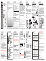
Guide
d'utilisation
CARACTÉRISTIQUES
Veuillez lire et vous assurer
de comprendre parfaitement
ce manuel avant d'installer
ou d'utiliser le thermostat.
• Afficheur à CL très lisible.
• Température facile à
régler.
• Modes chauffage, arrêt et
climatisation et
commutateur de contrôle
automatique du
ventilateur.
Ce thermostat remplace la plupart des thermostats résidentiels communs et
est conçu pour la plupart des systèmes de basse tension à gaz, au mazout
et électriques.
INSTALLATION
PAGE 1
PAGE 2
PAGE 3 PAGE 4 PAGE 5
PAGE 6 PAGE 7
PAGE 8 PAGE 9 PAGE 10
FAN
ON AUTO
COOL
OFF
HEAT
COOL
ON
à environ 1,5 m (5 pi) du plancher.
Le thermostat devrait être monté :
CHOIX D'UN EMPLACEMENT CONVENABLE POUR UN NOUVEAU THERMOSTAT
dans une pièce très fréquentée ou près de celle-ci, préférablement sur une cloison intérieure.
contre un mur qui ne dissimule pas de tuyaux ou de conduites.
près d'une fenêtre, contre un mur extérieur ou près d'une porte qui mène à l'extérieur.
ÉVITEZ d'installer le thermostat :
contre un mur exposé à la chaleur du soleil, d'une lampe, d'un foyer ou autres sources de
chaleur qui pourraient fausser la lecture.
près d'une bouche de chauffage ou d'un conduit de reprise ou dans le courant d'air généré par
ceux-ci.
contre un mur qui dissimule des tuyaux ou une cheminée.
dans un endroit où la circulation d'air est réduite, derrière une porte ou dans une alcôve par
exemple.
Type de système
Gaz – veilleuse continue
Gaz – allumage électronique
Gaz – chaudière à eau chaude
Gaz – système à circuit basse tension (millivolt)
Mazout – chaudière à eau chaude
Mazout – air pulsé
Électrique – air pulsé
Climatiseur électrique
Plinthes électriques (120/240 V)
Thermopompe/Systèmes à phases multiples
Compatible avec le thermostat
Oui
Oui
Oui
Oui
Oui
Certains modèles
Certains modèles
Non
Non
Oui
COMPATIBILITÉ
En règle générale, les appareils à circuit de commande basse tension sont
compatibles avec ce thermostat. En cas de doute sur la compatibilité de votre
appareil de chauffage ou de climatisation, communiquez avec notre service
technique au 1-888-468-6876.
*N'EST PAS COMPATIBLE AVEC LES SYSTÈMES 120/240 V.
INSTALLATION
Voici les outils dont vous pourriez avoir besoin pour l'installation du thermostat :
Un tournevis à pointe cruciforme ( )
Du ruban-cache (Pour envelopper temporairement le bout des fils et identifier les fils)
Une pince coupe-fil/à dénuder (pour dénuder les fils, au besoin)
Une perceuse électrique avec mèche de 3/16 po (pour percer des trous dans le mur, au besoin)
Un niveau (pour mettre le thermostat parfaitement à l'horizontale)
INSTALLATION
REMPLACEMENT DE L'ANCIEN THERMOSTAT
COUPEZ LE COURANT au système de chauffage ou au panneau de disjoncteurs ou
de fusibles.
Ouvrez soigneusement l'emballage du nouveau thermostat, qui comprend une
plaque de montage, un sachet de vis et des instructions. Conservez la facture.
Retirez le couvercle de l'ancien thermostat. S'il ne s'enlève pas lorsqu'on le force un
peu vers le bas, vérifiez si une vis retient le couvercle et enlevez-la.
Desserrez les vis qui retiennent le thermostat au mur et dégagez-le de sa plaque de
montage.
Débranchez les fils de l'ancien thermostat ou de sa plaque de montage. Identifiez
chaque fil avec du ruban-cache en écrivant la désignation du connecteur où il était
branché. S'il n'y a que deux fils, il n'est pas nécessaire de les identifier.
S'il y a un fil supplémentaire qui n'est pas raccordé à l'ancien thermostat, il n'aura pas
non plus à être raccordé au nouveau.
Après avoir choisi un emplacement pour votre nouveau thermostat, vous pouvez si
vous le désirez faire appel à un technicien pour le raccordement des fils.
Pour éviter d'endommager le compresseur, ne faites pas fonctionner le système
oo
de climatisation lorsque la température extérieure est inférieure à 10 C (50 F).
*
Avant d'installer le thermostat, vérifiez tout d'abord si les systèmes de chauffage et de
climatisation fonctionnent normalement. S'il y a un problème, faites réparer le
système par un réparateur avant de remplacer le thermostat.
Faites attention de ne pas laisser les fils se rétracter dans le mur et ne laissez pas les
fils se toucher entre eux.
Les fils sont généralement désignés « W », « Y », « G » et « R ».
INSTALLATION
INSTALLATION DE LA PLAQUE ARRIÈRE
La plaque arrière doit être fixée au mur le grand trou vers le haut.
Passez les fils par le grand trou au centre et tenez la plaque bien à plat contre le mur.
Choisissez deux trous de montage et faites des marques sur le mur au moyen d'un
crayon. Aidez-vous d'un niveau pour vous assurer que la plaque est parfaitement
horizontale.
Retirez la plaque et percez deux trous de 3/16 po aux endroits où vous avez fait des
marques au crayon.
Insérez des chevilles dans les trous et enfoncez-les complètement. Tapotez-les avec
un marteau au besoin.
Fixez la plaque au mur au moyen des deux vis fournies. Assurez-vous que les
connecteurs sont bien en haut.
Détachez soigneusement la plaque arrière du thermostat en dégageant les quatre
languettes de retenue fixées dans les coins, au dos de la plaque arrière. Tirez
fermement, mais SANS vous aider d'un tournevis.
INSTALLATION
RACCORDEMENT DES FILS AUX CONNECTEURS
Selon votre type de système de chauffage ou de climatisation, vous
aurez à raccorder de 2 à 5 fils au thermostat.
Si votre ancien thermostat comporte un fil « C », veuillez enrouler
sa partie exposée de ruban d'électricien et le laisser de côté : ce
fil n'est pas nécessaire avec ce type de thermostat.
Si vous disposez d'un fil « Rc » et d'un fil « R », vous pouvez les
raccorder tous les deux au connecteur « R » du thermostat.
Si vous n'êtes pas certain des raccordements ou s'il s'agit d'une
nouvelle installation, référez-vous au guide de câblage ci-dessous.
Raccordez les fils (que vous avez préalablement identifiés) aux connecteurs correspondants. Utilisez
un tournevis pour serrer fermement les fils. Assurez-vous que chaque fil ne touche qu'à un seul
connecteur.
Relais de la
climatisation
Relais du
ventilateur
Relais du
chauffage
DIAGRAMME DE CÂBLAGE
Relais du
chauffage
Chauffage 2 fils
Chauffage/climatisation 4 fils
Chauffage 3 fils
INSTALLATION
RÉGLAGE DU CAVALIER D'ACTIVATION DU VENTILATEUR
Selon le système de chauffage de votre domicile, vous pourriez avoir à modifier la position
du cavalier pour l'activation du ventilateur. Le cavalier est situé au-dessus du compartiment à
piles.
HG – placez le cavalier à cet endroit pour les systèmes de chauffage au gaz ou au
mazout. Ce réglage donne le contrôle du ventilateur au système de chauffage plutôt
qu'au thermostat. Ce réglage vaut pour la plupart des systèmes.
HE – placez le cavalier à cet endroit pour les systèmes de chauffage électriques. Sous
ce réglage, le thermostat actionne le ventilateur en même temps que le chauffage.
Le cavalier sera déjà en position HG, car c'est le réglage par défaut qu'on lui donne à l'usine.
Il est donc inutile de changer le réglage si votre système de chauffage est au gaz ou au
mazout.
Si vous devez changer le réglage, sortez le petit bloc noir rectangulaire et placez-le dans sa
nouvelle position en le poussant à fond.
INSTALLATION
INSTALLATION DES PILES
Ce thermostat fonctionne sur deux piles « AA ». Lorsque les piles sont faibles, le symbole de
pile ( ) clignote. Il est recommandé de remplacer les piles une fois l'an.
Détachez le thermostat de la plaque arrière.
Installez deux piles « AA » dans le compartiment à piles, selon la polarité indiquée.
Immédiatement après l'installation des piles, le thermostat se mettra en mode de
sélection de l'échelle de température. La température ambiante apparaîtra à
o
l'affichage et le symbole « C » clignotera.
oo
CHOIX DE L'ÉCHELLE DE TEMPÉRATURE ( C ou F)
Remettez le thermostat sur la plaque arrière.
oo
Remarque : Le choix de l'échelle de température ( C ou F) doit être fait immédiatement
après l'installation des piles.
o
Pressez le bouton HAUT ou BAS pour basculer l'échelle de température entre C et
oo
F. Si vous ne pressez aucun bouton avant 12 secondes, l'échelle C sera choisie par
défaut et le thermostat passera à l'affichage normal.
REMARQUE : La sélection de l'échelle de température °C ou °F ne se fait qu'une fois au
démarrage. Par conséquent, si vous désirez le changer plus tard, vous devrez réinitialiser
le thermostat en appuyant sur la touche RESET au-dessus du compartiment à piles et
sélectionner °C ou °F en utilisant la bouton HAUT ou BAS.
Pour fixer le boîtier du thermostat à la plaque arrière déjà vissée au mur, il
suffit de bien aligner les deux parties et d'enclencher les quatre languettes
dans le dos du thermostat.
POUR FIXER LE THERMOSTAT À LA PLAQUE ARRIÈRE
COUPEZ LE COURANT au système de chauffage ou au panneau de disjoncteurs ou de fusibles
avant d'effectuer le raccordement des fils.
AFFICHAGE ET BOUTONS
emplacement des boutons
Bouton HAUT
Affichage de la température
oo
Échelle de température ( C ou F)
Mode de température
affichage à CL
Bouton BAS
Mode de réglage de température
FAN
ON AUTO
COOL
OFF
HEAT
COOL
ON
1
2
1
2
1
2
Mode de chauffage ou de
climatisation
Indicateur de marche
3
4
5
6
FONCTIONNEMENT
COMMUTATEUR CHAUFFAGE-ARRÊT-CLIMATISATION
Position OFF
- Si le commutateur est à la position OFF, les systèmes de chauffage et climatisation sont à
l'arrêt.
Si le système de chauffage ou de climatisation est en marche (ON), le
symbole “ON” clignotera à l'affichage.
Position HEAT
- Mettez le commutateur en position HEAT pour mettre en marche le système de chauffage.
- Le symbole “HEAT” apparaît à l'affichage lorsque le commutateur est en position HEAT.
Position COOL
- Mettez le commutateur en position COOL pour mettre en marche le système de climatisation.
- Le symbole “COOL” apparaît à l'affichage lorsque le commutateur est en position COOL.
COMMUTATEUR DU VENTILATEUR - MARCHE/AUTO
Pour un contrôle automatique du ventilateur, mettez le commutateur du ventilateur en
position AUTO (FAN). En mode de climatisation, le ventilateur se met en marche et
s'arrête à la demande du climatiseur. En mode de chauffage, le ventilateur est
commandé par le système de chauffage et se met généralement en marche après
quelques minutes de préchauffage.
Pour un contrôle manuel du ventilateur, mettez le commutateur du ventilateur en
position ON. Le ventilateur sera alors continuellement en marche pour assurer une
bonne ventilation. Pour revenir en mode automatique, placez le commutateur à la
position AUTO.
FONCTIONNEMENT
RÉGLAGE DE LA TEMPÉRATURE
Pressez le bouton HAUT ou BAS une fois pour passer en mode de
réglage de la température. Le symbole ( ) apparaîtra et le réglage
actuel clignotera à l'affichage.
1
Pressez le bouton HAUT ou BAS jusqu'à la température voulue.
REMARQUE : Pour faire défiler rapidement
les chiffres, pressez le bouton sans le
relâcher. Le thermostat reviendra à l'affichage
normal (température ambiante) après 12
secondes si aucun bouton n'est pressé.
2
La température peut être réglée au demi-degré près.
oooo
La température peut être réglée entre 5 C et 35 C (41 F à 95 F).
FONCTIONNEMENT
AFFICHAGE DE LA TEMPÉRATURE AMBIANTE
La plupart du temps, c'est la température ambiante
qui est indiquée sur l'affichage à CL. Le symbole ( )
apparaît à l'affichage lorsque la température ambiante
est affichée.
o
La plage de température de l'affichage est de 0 C à
oo o
60 C (32 F à 140 F). Si la température est inférieure
ou supérieure à ces valeurs, le thermostat affichera LO
ou HI.
o
La sensibilité du thermostat est de 0,1
POUR VOIR LE RÉGLAGE DE LA TEMPÉRATURE
Presser le bouton HAUT ou BAS une fois pour voir le
réglage de température du thermostat. Le symbole
( ) apparaîtra et le réglage clignotera à l'affichage.
REMARQUE : Le thermostat comprend un délai de sécurité pour protéger le système
de chauffage et de climatisation :
- Lorsque le système de chauffage est activé, il continuera de fonctionner pendant au moins
2 minutes même si le réglage de température est modifié.
- Lorsque le système de chauffage est désactivé, il demeurera désactivé pendant au moins
2 minutes avant de s'allumer.
- Lorsque le système de climatisation est activé, il continuera de fonctionner pendant au
moins 4 minutes même si le réglage de température est modifié.
- Lorsque le système de climatisation est désactivé, il demeurera désactivé pendant au
moins 4 minutes avant de s'allumer.
RETOUR AUTOMATIQUE DE L'AFFICHAGE
Quelque soit le mode de réglage, le thermostat reviendra
à l'affichage normal (température ambiante) après 12
secondes si aucun bouton n'est pressé.
DÉPANNAGE
GARANTIE LIMITÉE D’UN AN
Dégagez les languettes de
retenue pour détacher la
plaque arrière du thermostat.
NIVEAU
+
+
Marquez
l'emplacement
des trous avec
un crayon.
Connecteurs
métalliques
Plaque arrière
Mur
Plaque
arrière
Connecteurs
métalliques
Fils
HEAT
PROBLÈME SOLUTION
Commutateur chauffage-arrêt-
climatisation
3
Commutateur du ventilateur -
marche/auto
4
4 3
PAGE 11 PAGE 12 PAGE 13 PAGE 14
H
G
H
G
HEHE
H
G
H
G
H
E
H
E
Remarque : Ce thermostat requiert deux piles « AA » pour fonctionner.
Assurez-vous qu'elles sont bien installées.
Relais du
ventilateur
Relais du
chauffage
L'affichage ne s'allume pas.
Le symbole de pile ( )
clignote.
Le système de chauffage ne se
met pas en marche.
Le système de chauffage ne se
met pas en marche, mais le
symbole ON clignote.
Le système de climatisation ne
se met pas en marche.
Le système de climatisation ne se
met pas en marche, mais le
symbole ON clignote.
1)
2)
Assurez-vous que l'interrupteur du climatiseur est à ON.
Accordez au système un peu de temps pour démarrer. Si le système ne démarre toujours
pas, vérifiez encore une fois le câblage du thermostat. (Voir à la page 6).
1)
2)
3)
4)
Assurez-vous que le thermostat est réglé à COOL.
Vérifiez si la température ambiante n'est pas inférieure à celle qui est programmée.
Vous pourriez avoir à attendre jusqu'à 5 minutes avant que le climatiseur ne démarre. Le
thermostat est doté d'un dispositif de sécurité qui prévient les mises en marche et arrêts
répétés.
La climatisation devrait démarrer après 5 minutes. Lorsque le système de climatisation est
en marche, le symbole ON clignotera.
1)
2)
3)
Assurez-vous que l'interrupteur du système de chauffage est à ON et que la veilleuse est
en marche.
Accordez au système un peu de temps pour démarrer. La plupart des systèmes ont un
cycle de préchauffage avant l'activation du ventilateur. Le cavalier HE/HG du thermostat
est incorrectement réglé. (Voir à la page 7).
Si le système ne démarre toujours pas, vérifiez encore une fois le câblage du thermostat.
(Voir à la page 6).
1)
2)
3)
4)
Assurez-vous que le thermostat est réglé à HEAT.
Vérifiez si la température ambiante n'est pas supérieure à celle qui est programmée.
Vous pourriez avoir à attendre jusqu'à 2 minutes avant que le chauffage ne démarre. Le
thermostat est doté d'un dispositif de sécurité qui prévient les mises en marche et arrêts
répétés.
Le chauffage devrait démarrer après 2 minutes. Lorsque le système de chauffage est en
marche, le symbole ON clignotera.
-
-
Les piles sont faibles. Remplacez-les avec des piles alcalines neuves.
Remarque : On recommande de remplacer les piles une fois l'an, même si l'indicateur de
pile faible ne clignote pas.
- Vérifiez si les piles sont bien installées.
- Assurez-vous que les piles sont en bon état et qu'elles sont du bon type.
- Appuyez sur le bouton de RÉARMEMENT situé au dos du thermostat, au-dessus du
compartiment à piles.
HEAT
HEAT
H
G
H
G
H
E
H
E
RÉARMEMENT
RÉARMEMENT
Si le thermostat affiche un affichage anormal ou si vous
désirez changer l'échelle de température (°C ou °F), utilisez
un objet pointu pour appuyer sur la touche RÉARMEMENT
(RESET).
UPM garantit que ce produit, à l'exception des piles, est exempt de tout défaut matériel et de fabrication et qu'il est couvert par une
garantie limitée, dans des conditions normales d'usage et de service, pendant une période d’un an qui commence depuis la date
de l'achat par le consommateur.
Si à n'importe quel moment durant la période de garantie, le produit est défectueux ou ne fonctionne pas correctement, UPM le réparera
ou le remplacera (à la discrétion d'UPM) et ce dans une période raisonnable de temps.
Si le produit est défectueux
(i) Retourner le, avec la preuve datée de l'achat, au revendeur où vous l'avez acheté, ou
(ii) Emballer le soigneusement, avec la preuve datée de l'achat et une courte description du mauvais fonctionnement, et envoyer le
tout par poste, franc de port, à l'adresse suivante:
UPM Marketing Inc.
Return Goods
Unit 10B - 250 Shields Court
Markham, Ontario
L3R 9W7
Cette garantie ne couvre pas les frais d'enlèvement ou de réinstallation. Cette garantie ne appliquera pas s'il est prouvé par UPM que le
défaut ou le mauvais fonctionnement aurait été causé par un dommage qui s'est produit pendant que le produit était en possession du
consommateur.
La seule responsabilité d'UPM sera de réparer ou de remplacer le produit selon les termes mentionnés ci-dessus. UPM NE POURRA EN
AUCUN CAS ETRE TENU RESPONSABLE POUR LES PERTES OU DOMMAGES D'AUCUNE SORTE, Y COMPRIS LES DOMMAGES
INDIRECTS OU CONSECUTIFS RESULTANT DIRECTEMENT OU INDIRECTEMENT, D'UNE RUPTURE DE GARANTIE, EXPRESSE OU
TACITE, OU D'UNE AUTRE DEFAILLANCE DE CE PRODUIT. Certains états n'autorisent pas l'exclusion ou la limitation de dommages
indirect ou consécutifs, alors la limitation peut ne pas vous être applicable.
UPM NE FAIT AUCUNE AUTRE GARANTIE QUE CELLE PRÉVUE DANS LA PRÉSENTE GARANTIE ET EXCLUE EXPRESSÉMENT TOUTE
AUTRE GARANTIE SUR CE PRODUIT. LA DUREE DES GARANTIES TACITES, Y COMPRIS LES GARANTIES COMMERCIALES ET
D'APTITUDE A UN EMPLOI PARTICULIER, EST CI-APRES LIMITEE A UNE DUREE D’UN AN DE CETTE GARANTIE. Certains états
n'autorisent pas des limitations sur la durée d'une garantie tacite, alors la limitation ci-dessus peut ne pas vous être applicable.
Cette garantie vous donne des droits légaux particuliers, et vous pouvez avoir d'autres droits qui peuvent varier d'Etat à Etat.
Si vous avez des questions concernant cette garantie, veuillez écrire à:
UPM Marketing Inc.
Customer Service Department
Unit 10B - 250 Shields Court
Markham, Ontario
L3R 9W7
Ou téléphoner au 1-888-GO-TO-UPM (1-888-468-6876), Lundi au Vendredi de 9:00 à 17:00 heures.
THERMOSTAT
THM101B
3
4
5
1
6
7
COOL
ON
HEAT
2
7
Indicateur de pile faible
-
 1
1
-
 2
2


UPM THM101B Le manuel du propriétaire
- Catégorie
- Thermostats
- Taper
- Le manuel du propriétaire
dans d''autres langues
- English: UPM THM101B Owner's manual
Documents connexes
Autres documents
-
Honeywell RTH7600D, RET97C Le manuel du propriétaire
-
Robertshaw RS2210C Manuel utilisateur
-
-
-
-
-
Honeywell RTH7400 Manuel utilisateur
-
Honeywell RTH4300B Manuel utilisateur
-
-
ETA Systems 800VA Manuel utilisateur