QSC PLD4.2 Guide de démarrage rapide
- Catégorie
- Haut-parleurs de la barre de son
- Taper
- Guide de démarrage rapide

PLD Amplifier
Quick Start Guide
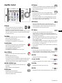
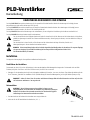
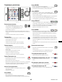
EXPLANATION OF TERMS AND SYMBOLS
The term “WARNING!” indicates instructions regarding personal safety. If the instructions are not followed the result may be bodily injury or death.
The term “CAUTION!” indicates instructions regarding possible damage to physical equipment. If these instructions are not followed, the result might
be equipment damage that is not covered under the warranty.
The term “IMPORTANT!” indicates instructions or information that are vital to the successful completion of the procedure.
The term "NOTE" indicates additional useful information.
The lightning flash with arrowhead symbol in a triangle is to alert the user to the presence of uninsulated dangerous voltage within the
product's enclosure that may constitute a risk of electric shock to humans.
The exclamation point within an equilateral triangle is to alert the user to the presence of important safety, and operating and
maintenance instructions in this manual.
NOTE:
This Quick Start Guide assumes starting with the amplifier's basic factory configuration, with four separate inputs and
four separate outputs. For detailed instructions for custom configurations refer to the PLD User Guide (TD-000368).
Installation
The following steps are written in the recommended installation order.
Rack Mount the Amplifier
The PLD Series amplifiers are designed to mount in a standard 19-inch equipment rack. The amplifiers are 2RU high. The PLD4.3 and PLD4.5 are
381 mm (15 in) deep, while the PLD4.2 is 229 mm (9 in) deep.
1. Secure the amplifier in the rack with eight screws (not supplied)—four in front and four in back. For complete instructions refer to document
TD-000050, Rear Rack Ears Installation Guide, which can be found on the QSC website (www.qsc.com)
CAUTION!:
Be sure that nothing blocks the front or rear ventilation openings and that each side has a clearance of at least
2 cm.
AC Mains
WARNING!:
When the AC power is on, there may be potentially dangerous voltage at
the output terminals on the rear of the amplifier. Be careful not to touch these contacts.
Turn off the AC mains disconnect switch before making any connections.
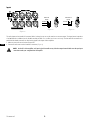
1. Make sure the power switch on the rear of the amplifier is off.
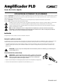
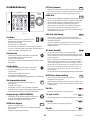
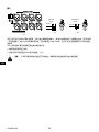
2. Plug the IEC power cord into the AC receptacle. (Figure 1)
— Figure 1 —
TD-000351-00-E
*TD-000351-00*
TD-000351-00-E

2
TD-000351-00-E
EN
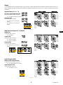
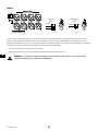
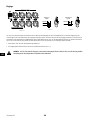
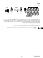
Inputs
— Figure 2 —
— Figure
1
3
2
Balanced
Inputs
1
Ground
3
Negative
2
Positive
3 — — Figure
Unbalanced
Inputs
1+3
Ground
2
Positive
1
3
2
4 —
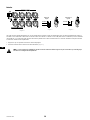
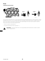
The audio inputs are four female XLR connectors labeled 1 through 4; any one can be routed to one or more outputs. The inputs have an impedance
of 10 kΩ balanced or unbalanced, and a selectable sensitivity of either +4 or +14 dBu (1.23 V rms or 3.9 V rms). The four male XLR connectors are in
parallel with the female connectors for daisy chaining signals to the inputs of other amplifiers.
1. Make sure your audio source devices are turned off.
2. Connect the audio sources to the female XLR connectors. (Figure 2)
NOTE:
On the PLD Series amplifies, each input's signal is routable to any of the the output channels. Make sure that your input
connections match your configuration of the amplifier.

3
TD-000351-00-E
EN
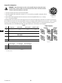
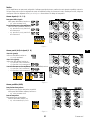
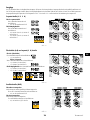
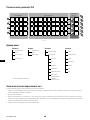
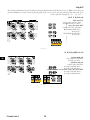
Outputs
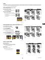
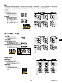
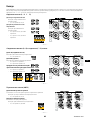
The PLD amplifiers have four configurable outputs. You can set power, combine outputs (bridged and parallel), and adjust the DSP for each one. The
output connections are enabled by relays, and they follow the configuration selected by the user. Use Figures 5 through 7 as references for wiring the
loudspeakers.
— Figure 5 —
— Figure 6 —
— Figure 7 —
Separate Channels (A B C D)
Up to four separate loudspeaker loads
Use up to four two-wire cables; connect to
• 1+/1- on outputs A through D as needed
Bi-amp operation
Use four-wire cables; connect to
• 1+/1- (CH A) and 2+/2- (CH B) on
output A
• 1+/1- (CH C) and 2+/2- (CH D) on
output C
Bridged (A+B) and Separate (C D) Channels
Bridged (A+B)
Use two-wire cable; connect to
• 1+/1- on output X
Separate C & D
Use two-wire cables; connect to
• 1+/1- (CH C) on output C
• 1+/1- (CH D) on output D
Bi-amp C and D
Use four-wire cable; connect to
• 1+/1- (CH C) and 2+/2- (CH D) on
output C
Parallel Channels (ABCD)
Multiple parallel loudspeaker loads
Use up to four two-wire cables; connect to
• 1+/1- on outputs A through D as needed
Single loudspeaker load
Use two-wire cable; connect to
• 1+/1- on output A, B, C, or D

4
TD-000351-00-E
EN
Connect the Loudspeakers
WARNING!:
When the AC power is on, there can be potentially dangerous voltage at the output
terminals on the rear of the amplifier. Be careful not to touch these contacts. Turn off the AC mains
disconnect switch before making any connections.
1. Turn off the AC mains power switch on the back of the amplifier.
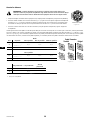
2. Wire the loudspeaker cables to male NL4 connectors (Figure 8) as needed for your amplifier's configuration. Refer to
Table 1 for details.
3. Plug the cables into the appropriate chassis NL4 connectors on the rear of the amplifier. Refer to Figure 5 through
Figure 7 for connection diagrams.
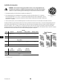
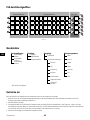
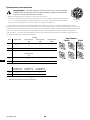
The following table shows you which pins on which output you can use for each mode. Where there is more than one connector for a given mode,
the PLD allows you to use one, all, or some of the available connectors. For example, in ABCD Parallel mode, you can use pins 1+ and 1- of outputs
A through D in any combination; the pins of all the outputs are in parallel and electrically the same. It is recommended that where the pins are
electrically the same, you use all available pins whether by jumpers between pins, or direct wiring to each loudspeaker
Mode
NL4 Separate AB Parallel ABC Parallel ABCD Parallel
A
Ch A 1+ / 1-
1+ / 1- 1+ / 1- 1+ / 1-
Ch B 2+ / 2-
1
B
1+ / 1- 1+ / 1- 1+ / 1- 1+ / 1-
CD Parallel
C
Ch C 1+ / 1-
1+ / 1- 1+ / 1- 1+ / 1-
Ch D 2+ / 2-
1
D
1+ / 1- 1+ / 1- 1+ / 1-
A+B Bridged C+D Bridged AB+CD Bridged
X
1+ / 1- 2+ / 2-
1
1+ / 1-
Y
1+ / 1-
— Table 1 —
1 For Bi-Amp operation.
— Figure 8 —
1+
1-
2-
2+
Male NL4 Wiring
— Figure 9 —
A
C
B
D
X
Y
Standard Bridged
Output Connectors

5
TD-000351-00-E
EN
Amplifier Control
— Figure 10 —
OUTPUT
HOME
MASTER
CONTROL
-10
-20
LIM
SEL
MUTE
A
1
SEL
MUTE
B
2
SEL
MUTE
C
3
SEL
MUTE
D
4
CLIP
SIG
INPUT
ENTER
EXIT
GAIN
(power
button)
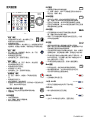
Off Mode
• When the rear power switch is off, the amplifier is
not operable. The front panel power button is not
illuminated. The switch is the AC mains disconnect.
• When you turn the power switch on, the amplifier enters the mode it
was in when power was removed. The power button will illuminate
according to the mode.
Run Mode
• From Standby or Mute All modes, press and release the
power button on the front panel.
• The power button will illuminate in blue.
• The amplifier is fully operable and can pass audio.
Standby Mode
• From Mute All or Run modes, press and hold the power
button on the front panel for two to three seconds.
• The power button will illuminate solid red.
• The front panel LCD will shut off.
• The amplifier is not operable and will not pass audio.
Mute All Mode
• From the Run Mode, press and release the power button
quickly.
• The power button will flash red.
• The outputs will mute on all channels.
• The front panel and DSP functionality are still fully operable, and you
can make any changes you need to. Any settings you make will be
saved and effected when yu put the amplifier into Run Mode.
MASTER CONTROL Knob
• Scrolls up/down and right/left to select menu items and
parameters
• Adjusts settings on selected parameters
ENTER Button
• Navigates into the menu structure
• Enters the edit mode for adjusting parameters
• Confirms the changes made
EXIT Button
• Navigates out of the menu structure and parameter selection.
• In the edit mode, pressing EXIT reverts the value back to its prior
state, and exits the edit mode.
HOME Button
• If you are on the Home screen, pressing HOME displays
the alternate Home screen. Pressing HOME again returns you to the
primary Home screen.
• If you are on a navigation screen, pressing HOME takes you Home.
• If you are on an edit screen, pressing HOME will confirm any value
being edited and take you to the HOME screen.
GAIN Button
• Pressing the GAIN button from any screen takes you to the
output gain screen for the most recently accessed output channel.
• Pressing GAIN again confirms the gain change and returns to the
screen you were on when you pressed GAIN.
SEL Buttons
• Use these buttons to navigate between input channels or
output channels. For example, if you are adjusting output gain on
channel A, pressing the channel B SEL button will then take you to the
gain adjustment for channel B.
• These buttons change both INPUT and OUTPUT selection at the same
time. For example, if you select OUTPUT A then switch to an Input
screen, you are on Input 1.
• The SEL buttons are active on any Input or Output screen as indicated
by an illuminated SEL button, and a label in the upper right corner of
the screen (Input 1–4 or Output A–D).
• The SEL buttons illuminate in blue for output channels, and amber for
input channels.
MUTE Buttons
• Use these buttons to mute individual output channels.
• When the amplifier's output configuration changes, the MUTE buttons
engage automatically. You must manually unmute the channels.
LIM LEDs
• Illuminates red when the limiter engages.
-10 and -20 LEDs
• Indicates the output level of the channel in relation to its maximum.
CLIP LEDs
• Illuminates red when the input section clips.
SIG LEDs
• Illuminates blue when an input signal higher than -40 dB is present.
ENTER
EXIT
HOME
GAIN GAIN
SEL SEL
MUTE
LIM
-10 & -20
CLIP
SIG

6
TD-000351-00-E
EN
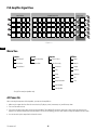
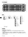
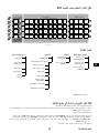
PLD Amplifier Signal Flow
— Figure 11 —
A
D
B
C
X
Y
1
4
3
2
Input Settings Output Processing Amp Config.
Sensitivity
Switch
A/D Meter Gain
Source
Select
Mute
High-pass
Filter
Gain /
Polarity
Low-pass
Filter
5-Band
PEQ
Delay
RMS / Peak
Limiter
D / A
A
Meter
Sensitivity
Switch
A/D Meter Gain
Source
Select
Mute
High-pass
Filter
Gain /
Polarity
Low-pass
Filter
5-Band
PEQ
Delay
RMS / Peak
Limiter
D / A
B
Meter
Sensitivity
Switch
A/D Meter Gain
Source
Select
Mute
High-pass
Filter
Gain /
Polarity
Low-pass
Filter
5-Band
PEQ
Delay
RMS / Peak
Limiter
D / A
C
Meter
Sensitivity
Switch
A/D Meter Gain
Source
Select
Mute
High-pass
Filter
Gain /
Polarity
Low-pass
Filter
5-Band
PEQ
Delay
RMS / Peak
Limiter
D / A
D
Meter
Button
Activated
Crossover
Set by Preset or Wizard
Menu Tree
Presets Inputs Outputs Utilities
Preset Recall Input Sensitivity Source Select Status
Preset Save Input Gain Spkr Processing Amp ID
Preset Wizard Crossover Display
PEQ Lockout
Delay Password
Limiter GPI
Array Correction* GPO
Load Speaker
Save Speaker
*For QSC line array loudspeakers only.
AC Power On
After connecting the outputs to the loudspeakers, you may turn the amplifier on.
1. Make sure the outputs levels on all audio source devices (CD players, mixers, instruments, etc.) are all the way down.
2. Turn on all the audio sources.
3. Turn on the AC mains power switch on the back of the amplifier. The amplifier will resume the state it was in when power was removed. If the
amplifier is in Standby or Mute All mode (Power button LED solid red or blinking), press the Power button to change the amplifier into Run mode.
4. You can now raise up the output levels of the audio sources.

7
TD-000351-00-E
EN
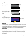
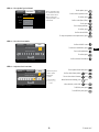
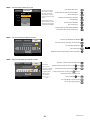
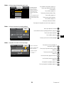
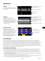
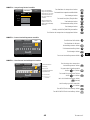
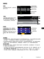
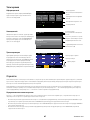
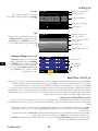
Screen Types
— Figure 12 —
Informational
Informational screens, like the HOME screen, are
designed to provide you with a good amount of
useful information at a glance.
F1: A B C D
Full
+1.5 dB
A - FR
+1.5 dB
C - FR
Full
+1.5 dB
D - FR
Full
121 V 7.2 AAC Voltage: AC Current:
Home (Press HOME for more information)
+3.5 dB
B - FR
Full
Amp Status:
OK
Preset # and configuration
Location
Channel configuration and gain
AC voltage and current
Amplifier status
— Figure 13 —
Navigational
Navigational screens provide the means to move
around and select menu items. Use the Master
Control knob, ENTER, and EXIT buttons for
navigation. This is one type of navigational screen
among many.
Preset # and configuration
Location
Current menu selection
Adjacent menu selection
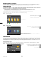
— Figure 14 —
Parameter Editing
Parameter Editing screens allow you to select, edit,
and confirm changes for various system parameters.
Use the ENTER button to edit and confirm changes
to parameters. Use the Master Control knob to select
parameter, and make adjustments. Use the EXIT
button to exit the edit mode without saving changes.
Gain
-7.0 dB
Gn/Pol
F1: A B C D
Polarity
POL+
Output
A
20 dB
-60 dB
Gain
-7.0 dB
Parameter being edited
Parameter not selected
Parameter selected
About Presets
The PLD amplifiers are driven by presets, and understanding how they work will help you get the most out of the amplifiers. A preset, in the context
of the PLD amplifiers, is a combination of amplifier configuration (inputs and outputs), DSP, and loudspeaker assignments. When a preset is recalled it
can change the output routing and any of the DSP settings.
The PLD amplifiers come with 20 unchangeable factory presets, as well as 50 slots for user-defined presets. The factory presets are starting points for
creating the settings you need for your particular installation. Factory presets F1 through F9 have no DSP or loudspeaker assignments—only routing
and output configurations. Factory presets F10 through F20 include basic DSP settings along with the routing and output configurations.
User-defined Presets
Presets U1 through U50 are all factory-configured the same as factory preset F1. Anytime you save a preset, it overwrites one of the user-defined slots.
There are three ways of creating user-defined presets.
• You can recall a user-defined preset, modify its parameters, and then either use SAVE (which will overwrite the one you recalled) or SAVE AS (to
create a new user-defined preset in a different slot).
• You can recall a factory preset, modify its parameters, and then use SAVE AS to make it a user-defined preset. The SAVE function is disabled for
factory presets.
• You can use the Preset Wizard to set the output configuration, power output, and other parameters, and then use SAVE AS to store them in one of
the user-defined preset slots.

8
TD-000351-00-E
EN
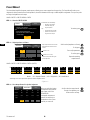
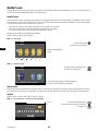
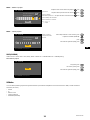
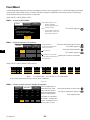
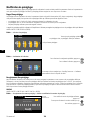
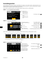
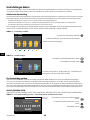
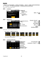
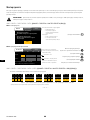
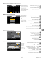
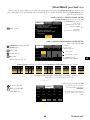
Preset Wizard
The Preset Wizard simplifies the preset creation process, allowing you to create a preset from the ground up. The Preset Wizard first asks you to
designate the desired power levels and load impedances; from that information it will assign a suitable amplifier configuration. Then you may select
and assign loudspeakers to each output.
HOME > PRESETS > PRESET WIZARD > ENTER
STEP 1 —
About the PRESET WIZARD
ABOUT SPEAKERS SAVE
Preset Wizard does the following:
• Configures the amplifier
• Loads DSP settings for assigned speakers
Tips:
• Start with the highest power
• Speakers do not need to be assigned
to each output
NEXT
Preset Wizard does the following:
• Configures the amplifier
• Loads DSP settings for
assigned speakers
Tips:
• Start with the highest power
• Speakers do not need to be
assigned to each output
To continue, press
ENTER
STEP 2 —
Adjust Impedance and Power
OUTPUTS SPEAKERS SAVE
A B C D
Output:
8.0 - - - - - -
Imped:
625 - - - - - -
Power:
Remaining Power Available: 1875 W
Enter Load Profile (Impedance and Power)
Adjust impedance based on the total
loudspeaker load connected to the
channel.
Default = 8 Ω
Default = min. for amp
Impedance and power settings are
dynamically linked.
Scroll to select (Impedance or Power)
To edit, press
Turn to adjust parameter
To confirm, press
Repeat for remaining
output channels
ENTER
ENTER
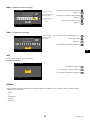
HOME > PRESETS > PRESET WIZARD > ENTER > (ENTER)
— Figure 15 —
- - -
B
25%
A
- - -
25%
D
- - -
25%
C
- - -
25%
AB
- - -
50%
D
- - -
25%
C
- - -
25%
CD
- - -
50%
AB
- - -
50%
A+B
- - -
50%
D
- - -
25%
C
- - -
25%
D
- - -
25%
ABC
- - -
75%
ABCD
- - -
100%
AB + CD
- - -
100%
A+B
- - -
50%
C+D
- - -
50%
*
Possible Output Mode Combinations using the Preset Wizard
Modes: A B = Separate Channels / A+B = Bridge Mode / AB = Parallel Mode
*Percentages are used to represent the power for different amplifier models.
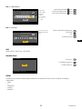
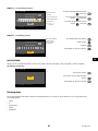
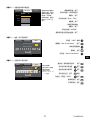
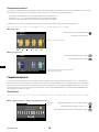
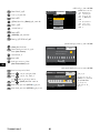
STEP 3 —
Select Output Channel for Speaker Assignment
OUTPUTS SPEAKERS SAVE
Assign
AssignAssign
Output:
A DCB
Imped:
8.0 8.08.08.0
Spkr:
- - - - - - - -- - - -- - - -
Assign
Power:
625 625625625
When you are finished setting
the impedance and power for
each output, scroll to the
SPEAKERS tab.
Loudspeaker assignment is
optional. You may assign a
loudspeaker to one or more
channels, or none at all.
Scroll to select the output channel.
To assign a loudspeaker, press
Continue to the next step.
ENTER

9
TD-000351-00-E
EN
STEP 4 —
Select Speaker Type for Channel
OUTPUTS SPEAKERS SAVE
Output:
A
ASSIGN
Full Range
Speaker:
Default
Band:
QSC AP-5152
Filter:
To edit speaker, press
Scroll to select a speaker model
To confirm, press
Scroll to select (Band, Filter)
To edit, press
Turn to adjust parameter
To confirm, press
Scroll to select ASSIGN
To assign the speaker to the output channel, press
Select the loudspeaker model
first; it will determine the band
and filter selections offered.
When you have finished
assigning loudspeakers, scroll
to the SAVE tab.
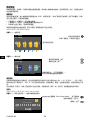
STEP 5 —
Select User Preset Number
Edit preset number or press EXIT
User Preset Number:
21
SAVE
New Preset Name
C o n f i g - A
OUTPUTS SPEAKERS SAVE
Scroll to the SAVE screen
To edit User Preset Number, press
Turn to adjust parameter
To confirm, press
Scroll to the New Preset Name
ENTER
ENTER
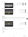
STEP 6 —
Assign New User Preset Name
Press ENTER to edit name
SAVE
M y S p k r
SAVE
SPEAKERSABOUT
New Preset Name
User Preset Number:
21
Character being edited
Indicates “Speaker
Profile Name”
is selected
Up to 21 characters
A - Z / a - z / 0 - 9 /
_ / - / space
To add speaker Preset Name, press
Scroll to desired letter position press
Turn to select desired character press
When finished with lettering, press twice
When finished, scroll to SAVE press
To RECALL preset, press
To not RECALL preset, press
ENTER
ENTER
ENTER
EXIT
ENTER
ENTER
EXIT
ENTER
ENTER
ENTER
ENTER
ENTER

10
TD-000351-00-E
EN
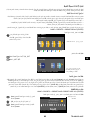
Modify Presets
To modify a preset, start with the desired output configuration, and then modify the input and output parameters as desired. Then save the preset. You
may also save the preset at intermediate points in the creation process.
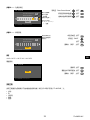
Recall a Preset
A preset includes the output configuration, input parameters, and loudspeaker profiles (DSP, load, and assignments). The amplifier includes 20 factory
presets that can be recalled but not overwritten and 50 slots for user-defined presets that may be recalled and overwritten. The factory default settings
in U1 through U50 are the same as in factory preset F1 (A B C D).
• Factory presets F1 through F9 are output configurations only; they involve no DSP settings.
• Factory presets F10 through F20 are output configurations along with basic DSP settings.
• The 50 user preset slots can be recalled, modified, and overwritten as desired.
Recalling a preset changes the configuration of the amplifier.
HOME > PRESETS > PRESET RECALL (ENTER)
STEP 1 —
Select Preset
A B C D
M M M M
F1: A B C D
F1: A B C D
Input Sub MF FullHFLF
Indicates presets available by
scrolling
Scroll to desired preset
20 factory and 50 user-defined
STEP 2 —
Confirm Selection
F1: A B C D
F18: 3-Way
Press ENTER to confirm selection
A+B
C D
M M M
The text at the bottom changes to: Recalling Preset now…
You may hear relays clicking inside the amplifier!
To select the preset configuration, press
To confirm the selection, press
ENTER
ENTER
Save a Preset
After modifying the inputs and outputs for all channels, save the current settings as one of the 50 user-defined presets (U1 through U50). If you start
with a factory preset, use SAVE AS. If you start with a user-defined preset, you may overwrite it using SAVE or write to a different one using SAVE AS.
SAVE AS
HOME > PRESETS > PRESET SAVE > PRESET SAVE AS > (ENTER)
STEP 1 —
Save a New Preset – Select and Edit Preset Number
Edit preset number or press EXIT
U1: A B C D
User Preset Number:
21
SAVE
New Preset Name
C o n f i g - A
To edit User Preset Number, press
Turn to select desired number (1 through 50)
To confirm, press
ENTER
ENTER
Current active
preset.

11
TD-000351-00-E
EN
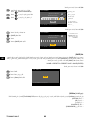
STEP 2 —
Name the Preset
Press ENTER to edit preset name
U1: A B C D
User Preset Number:
21
SAVE
New Preset Name
C o n f i g X A
Scroll to New Preset Name press
Scroll to desired letter position press
Turn to select desired character press
ENTER
ENTER
ENTER
Indicates editing
Indicates "Speaker
Profile Name"
is selected.
Up to 21 characters
A - Z / a - z / 0 - 9 /
_ / - / space
STEP 3 —
Save Preset
Press ENTER to save preset
U1: A B C D
User Preset Number:
21
SAVE
New Preset Name
C o n f i g X A
When you have finished the name, press
Scroll to SAVE
Press
To confirm SAVE, press
EXIT
ENTER
ENTER
Once the preset is saved,
it also becomes the active
preset.
SAVE
HOME > PRESETS > PRESET SAVE > SAVE (ENTER)
Utilities
The Utilities section provides the following amplifier information and functionality: Please refer to the PLD User Manual (TD-000368) for
complete details.
• STATUS
• ID
• Serial Number
• LOCKOUT
• PASSWORD.
Press ENTER to save preset
U1: A B C D
SAVE
Overwrite Preset
ENTER
EXIT
ENTER
To save, press
To exit without saving, press
To confirm SAVE, press

12
TD-000351-00-E
EN
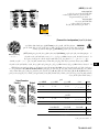
Mailing Address:
QSC, LLC
1675 MacArthur Boulevard
Costa Mesa, CA 92626-1468 USA
Telephone Numbers:
Main Number: +1 (714) 754-6175
Sales & Marketing: +1 (714) 957-7100 or toll free (USA only) (800) 854-4079
Customer Service: +1 (714) 957-7150 or toll free (USA only) (800) 772-2834
Facsimile Numbers:
Sales & Marketing FAX: +1 (714) 754-6174
Customer Service FAX: +1 (714) 754-6173
World Wide Web:
www.qsc.com
E-mail:
© 2015–2019 QSC, LLC. All rights reserved. QSC, the QSC logo are trademarks of QSC, LLC in the U.S. and other countries.
Patents may apply or be pending.
http://patents.qsc.com
If you would like a full copy of the PLD User manual, visit the QSC website at www.qsc.com, or contact Customer Service +1
714 957-7150 or toll free (USA only) (800) 772-2834 to receive a copy by mail.
Si desea obtener una copia completa del manual del usuario de la PLD, visite el sitio web de QSC en www.qsc.com, o
póngase en contacto con el Servicio al Cliente al +1 714 957-7150 o sin costo (sólo en EE.UU.) al (800) 772-2834 para
recibir una copia por correo.
Pour obtenir un exemplaire complet du manuel d’utilisation de la PLD, allez sur le site Web QSC à www.qsc.com ou
contactez le service clientèle au +1 714 957-7150 ou au (800) 772-2834 (numéro vert - USA seulement) pour recevoir un
exemplaire par courrier.
Ein vollständiges Exemplar des Benutzerhandbuchs für die PLD finden Sie auf der QSC-Website unter www.qsc.com. Sie
können sich unter +1 714 957-7150 oder unter der (nur in den USA) gebührenfreien Nummer +1 (800) 772-2834 auch an
den Kundendienst wenden, um sich ein Exemplar zuschicken zu lassen.
如果您需要 PLD 产品用户手册的完整副本,请访问 QSC 网站 www.qsc.com,或致电客户服务部门
+1 714 957-7150,或拨打免费电话(仅限美国)(800) 772-2834 通过邮件获取副本。
Если вам нужна полная копия руководства пользователя PLD, посетите веб-сайт QSC на www.qsc.com
или свяжитесь со службой по работе с клиентами (+1 714 957-7150 или по бесплатному телефону
(только для США) (800) 772-2834) для получения копии по почте.
: QSC PLD
) ( +1 714 957-7150 www.qsc.com
. )800( 772-2834

Amplificador PLD
Guía de inicio rápido
EXPLICACIÓN DE LOS TÉRMINOS Y DE LOS SÍMBOLOS
El término “¡ADVERTENCIA!” indica instrucciones con respecto a la seguridad personal. Si no se siguen dichas instrucciones, se pueden ocasionar lesiones o la muerte.
El término “¡PRECAUCIÓN!” indica instrucciones con respecto a posibles daños al equipo físico. Si no se siguen dichas instrucciones, se pueden ocasionar daños al
equipo que pueden no estar cubiertos por la garantía.
El término “¡IMPORTANTE!” indica instrucciones o información que son de vital importancia para completar satisfactoriamente el procedimiento.
El término “NOTA” se utiliza para indicar información adicional de utilidad.
El símbolo de un rayo con punta de flecha dentro de un triángulo sirve para alertar al usuario de la presencia de voltaje “peligroso” no aislado dentro
de la caja del producto, que puede ser de suficiente magnitud como para constituir un riesgo de descarga eléctrica a los seres humanos.
El signo de exclamación dentro de un triángulo equilátero sirve para alertar al usuario de la presencia de instrucciones importantes de seguridad,
utilización y mantenimiento en el manual.
NOTA:
Esta Guía de inicio rápido se basa en la configuración básica del amplificador, tal y como viene de fábrica. Cuatro entradas
independientes, y cuatro salidas independientes. Para obtener instrucciones detalladas a fin de realizar una configuración personalizada,
consulte el Manual del usuario para el amplificador PLD (TD-000368).
Instalación
Los siguientes pasos se han redactado en el orden de instalación recomendado.
Montaje del amplificador en bastidor
Los amplificadores de la serie PLD están diseñados para montarse en una unidad de bastidor (rack) estándar. Los amplificadores ocupan 2 unidades de rack (2 UR)
de alto; los modelos PLD4.3 y PLD4.5 tienen 381 mm (15 pulgadas) de profundidad, mientras que el PLD4.2 tiene 229 mm (9 pulgadas) de profundidad.
1. Fije el amplificador al bastidor (rack) con ocho tornillos (no incluidos), cuatro en la parte delantera y cuatro en la parte posterior. Para leer las instrucciones
completas, consulte la guía TD-000050 (“Guía de instalación del bastidor en los soportes de montaje posteriores”) que encontrará en el sitio web de QSC
(www.qsc.com)
¡PRECAUCIÓN!:
Asegúrese de que nada esté bloqueando las aberturas frontales o posteriores de ventilación, y que cada lado tenga una
separación mínima de 2 cm.
Línea eléctrica de CA (corriente alterna)
¡ADVERTENCIA!:
Cuando la alimentación de CA está activada, es posible que exista un voltaje
peligroso en los terminales de salida en la parte posterior del amplificador. Tenga cuidado para
no tocar estos contactos. Apague el interruptor de desconexión de la línea de alimentación
eléctrica principal de CA antes de hacer ninguna conexión.
1. Asegúrese de que el interruptor de encendido/apagado (power) en la parte trasera del amplificador esté apagado (off).
2. Conecte el cable de alimentación IEC al receptáculo de CA (corriente alterna). (Figura 1)
— Figura 1 —
TD-000351-00-E

14
TD-000351-00-E
ES
Entradas
— Figura 2 —
— Figura 3 —
1
3
2
Balanced
Inputs
1
Ground
3
Negative
2
Positive
— Figura 4 —
Unbalanced
Inputs
1+3
Ground
2
Positive
1
3
2
Hay cuatro conectores XLR hembra rotulados del 1 al 4 que proporcionan las entradas de audio a los amplificadores PLD. Una entrada individual puede enrutarse a
una salida o a una combinación de ellas. Puede usar de una a cuatro de las entradas. Las entradas son de 10 kΩ, balanceadas o no balanceadas, con una sensibilidad
seleccionable de +4 o +14 dBu. Hay cuatro conectores XLR macho en paralelo con los cuatro conectores hembra. Los conectores XLR macho sirven para la conexión
en cadena a las entradas de otros amplificadores.
1. Asegúrese de que sus dispositivos de fuentes de audio estén apagados.
2. Conecte los XLR de la fuente de entrada a los cuatro XLR hembra. (Figura 2)
NOTA:
La serie PLD ofrece la posibilidad de enrutar las entradas a diferentes salidas. Asegúrese de que las conexiones que usted haga aquí
coincidan con la configuración del amplificador.

15
TD-000351-00-E
ES
Salidas
Los amplificadores PLD disponen de cuatro salidas configurables. Puede establecer la potencia, combinar las salidas (puenteadas y en paralelo) y ajustar el DSP para
cada salida. Cuando cambia la configuración de salida del amplificador, también cambian las conexiones de salida, controladas mediante relés. Siga los diagramas de
las figuras 5 a 7 como referencia para cablear los altavoces.
Canales independientes (A B C D)
— Figura 5 —
Para cuatro cables separados
Utilice cuatro cables de 2 hilos para conectar a:
• 1+/1- en los conectores A – D
Para operar en biamplificado
Utilice dos cables de 4 hilos para conectar a:
• 1+/1- para el canal A y 2+/2- para el canal B
en el conector A
• 1+/1- para el canal C y 2+/2- para el canal D
en el conector C
Canales puenteados (A+B) y canales independientes (C D)
— Figura 6 —
Para A+B puenteado (en bridge)
Utilice un cable de 2 hilos para conectar a:
• 1+/1- en el conector X
Para C y D (independientes)
Utilice dos cables de 2 hilos para conectar a:
• 1+/1- para el canal C en el conector C
• 1+/1- para el canal D en el conector D
Para operar en biamplificado
, utilice un cable de 4 hilos para conectar a:
• 1+/1- para el canal C en el conector C
• 2+/2- para el canal D en el conector D
Canales en paralelo (ABCD)
— Figura 7 —
Para varios altavoces
Potencia completa para varios altavoces en paralelo
Utilice hasta cuatro cables de 2 hilos, conectados a
• 1+/1- en los conectores A – D
Para un altavoz
Potencia completa a un altavoz
Utilice un cable de 2 hilos, conectado a:
• 1+/1- en el conector A, B, C o D

16
TD-000351-00-E
ES
Conectar los altavoces
¡ADVERTENCIA!:
Cuando la alimentación de CA está activada, es posible que exista un voltaje peligroso en los
terminales de salida en la parte posterior del amplificador. Tenga cuidado de modo de no tocar estos contactos. Apague
el interruptor de desconexión de la línea de alimentación eléctrica principal de CA antes de hacer ninguna conexión.
1. Coloque el interruptor del suministro eléctrico principal de CA (en la parte posterior del amplificador) en la posición OFF (APAGADO).
2. Conecte el cableado del altavoz a los conectores NL4 macho (Figura 8) según sea necesario para la configuración del amplificador.
Consulte las Figuras 5 a 7 para ver los diagramas de cableado. Al combinar canales, QSC recomienda que conecte puentes entre
los terminales de salida que representen un mismo punto eléctricamente. Consulte la Tabla 1 para ver la información detallada
3. Conecte los conectores NL4 macho a los conectores NL4 hembra, en la parte posterior del amplificador, según la configuración
del amplificador.
La tabla siguiente muestra cuáles patillas en cuáles NL4 puede utilizar para cada modo. Donde haya más de un conector para un modo dado, el PLD le permite utilizar
uno, todos o algunos de los conectores disponibles. Por ejemplo, en el modo ABCD Parallel (ABCD en paralelo), puede utilizar las patillas 1+ y 1- de NL4 (A, B, C y D),
(A o B o C o D), o (A y B), y así sucesivamente; las patillas están todas en paralelo y eléctricamente representan el mismo punto. Se recomienda que, donde las patillas
sean eléctricamente las mismas, se utilicen todas las patillas disponibles, ya sea mediante puentes entre patillas o mediante el cableado directo a cada altavoz.
Modo
NL4 Separado AB en paralelo ABC en paralelo ABCD en paralelo
A
Canal A 1+ / 1-
1+ / 1- 1+ / 1- 1+ / 1-
Canal B 2+ / 2-
1
B
1+ / 1- 1+ / 1- 1+ / 1- 1+ / 1-
CD en paralelo
C
Canal C 1+ / 1-
1+ / 1- 1+ / 1- 1+ / 1-
Canal D 2+ / 2-
1
D
1+ / 1- 1+ / 1- 1+ / 1-
A+B puenteado C+D puenteado
AB+CD
puenteado
X
1+ / 1- 2+ / 2-
1
1+ / 1-
Y
1+ / 1-
— Tabla 1 —
2 Para operar en biamplificado.
— Figura 8 —
1+
1-
2-
2+
Cableado NL4 macho
— Figura 9 —
A
C
B
D
X
Y
Standard Bridged
Output Connectors

17
TD-000351-00-E
ES
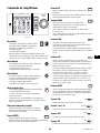
Control del amplificador
— Figura 10 —
OUTPUT
HOME
MASTER
CONTROL
-10
-20
LIM
SEL
MUTE
A
1
SEL
MUTE
B
2
SEL
MUTE
C
3
SEL
MUTE
D
4
CLIP
SIG
INPUT
ENTER
EXIT
GAIN
(power
button)
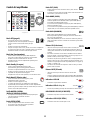
Modo Off (Apagado)
• El interruptor eléctrico posterior está apagado,
el amplificador está en estado inoperante. El interruptor
eléctrico desconecta del suministro eléctrico principal
de CA.
• El botón de encendido no está iluminado.
• Coloque el interruptor eléctrico en la posición de encendido. El amplificador
se encenderá en el modo en el que se encontraba cuando se desconectó la
alimentación. El botón de encendido se ilumina según el modo.
Modo Run (Funcionamiento)
• Desde los modos Standby (En espera) o Mute All (Silenciar
todo), pulse y suelte el botón de encendido en el panel frontal.
• El botón de encendido está iluminado de color azul.
• El amplificador está en estado completamente operativo; puede
transmitirse el audio.
Modo Standby (En espera)
• Desde los modos Mute All (Silenciar todo) o Run
(Funcionamiento), pulse y mantenga pulsado el botón de
encendido en el panel frontal durante dos a tres segundos.
• El botón de encendido se ilumina de color rojo continuo.
• La pantalla LCD del panel frontal está apagada.
• El amplificador no está en estado operativo; no se transmitirá el audio.
Modo Mute All (Silenciar todo)
• Desde el modo Run (Funcionamiento), pulse y suelte
rápidamente el botón de encendido.
• El botón de encendido parpadea en rojo.
• Las salidas están silenciadas y los amplificadores están apagados.
• El panel frontal y la funcionalidad DSP están en estado completamente
operativo. Se guardará cualquier cambio que hubiera hecho, el cual tendrá
efecto en el modo Run (Funcionamiento).
Perilla MASTER CONTROL
(RUEDA DE CONTROL GENERAL)
• Se desplaza hacia arriba/abajo y hacia la derecha/izquierda para
seleccionar elementos y parámetros del menú
• Ajusta los parámetros
Botón ENTER (INTRO)
• Permite la navegación dentro de la estructura de menús
• Accede al modo de edición para ajustar los parámetros
• Confirma los cambios que haya hecho
Botón EXIT (SALIR)
• Permite navegar fuera de la estructura de menús y de la selección
de parámetros.
• En el modo de edición, pulsar EXIT (SALIR) revierte el valor nuevamente a su
estado anterior, y sale del modo de edición.
Botón HOME (INICIO)
• Si usted se encuentra en la pantalla de inicio, pulsar HOME (INICIO)
mostrará la pantalla de inicio alternativa. Volver a pulsar HOME (INICIO)
lo devolverá a la pantalla principal de inicio.
• Si se encuentra en una pantalla de navegación, al pulsar HOME (INICIO),
le llevará a la pantalla de inicio.
• Si se encuentra en una pantalla de edición, pulsar HOME (INICIO) confirmará
cualquier valor que se esté editando y lo llevará a la pantalla de inicio.
Botón GAIN (GANANCIA)
• Pulsar el botón GAIN (GANANCIA) desde cualquier pantalla le
llevará a la pantalla de ganancia de salida para el canal de salida al cual se
tuvo acceso más recientemente.
• Pulsar GAIN (GANANCIA) una vez más confirma el cambio en la ganancia y
vuelve a la pantalla en la cual se encontraba en el momento de pulsar GAIN
(GANANCIA).
Botones SEL (Seleccionar)
• Utilice estos botones para navegar entre los canales de entrada y los
canales de salida. Por ejemplo, si está ajustando la ganancia de salida en el
canal A, pulsar el botón SEL del canal B le llevará al ajuste de ganancia para
el canal B.
• Estos botones cambian la selección tanto de ENTRADA como de SALIDA a
la vez. Por ejemplo, si selecciona la SALIDA A (OUTPUT A) y luego va a una
pantalla de entradas, estará en Input 1 (entrada 1).
• Los botones SEL (Seleccionar) permanecen actios en cualquier pantalla de
entradas o salidas, lo que se indica mediante un botón SEL iluminado, y una
etiqueta en la esquina superior derecha de la pantalla (Entrada 1 a 4 [Input 1-4]
o Salida 1 a 4 [Output 1-4]).
• Los botones SEL se iluminan en azul para los canales de salida, y en ámbar
para los canales de entrada.
Botones MUTE (Silenciar)
• Utilice estos botones para silenciar el audio del canal de salida
asociado.
• Cuando se modifique la configuración de salida, los botones MUTE (SILENCIAR)
se activarán automáticamente. Deberá desilenciar los canales de manera manual.
Indicadores LED LIM
• Se ilumina en rojo al activarse el limitador.
Indicadores LED de -10 y -20
• Indica los dB (decibelios) por debajo del nivel máximo de salida del canal.
INDICADORES LED CLIP (DE RECORTE)
• Se ilumina en rojo cuando se recorta la señal de entrada.
Indicadores LED SIG (DE SEÑAL)
• Se ilumina en azul cuando la señal supera -40 dB.
ENTER
EXIT
HOME
GAIN GAIN
SEL SEL
MUTE
LIM
-10 & -20
CLIP
SIG

18
TD-000351-00-E
ES
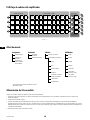
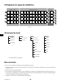
PLD Flujo de señales del amplificador
— Figura 11 —
A
D
B
C
X
Y
1
4
3
2
Ajustes de entrada Procesamiento de salida
Amp Config.
(configuración del amplificador)
Interruptor de
sensibilidad
A/D
(analógico
->digital)
Medidor Ganancia
Selección
de fuentes
Mute
(Silenciar)
Filtro paso
alto
Ganancia/
polaridad
Filtro paso
bajo
Ecualizador
paramétrico
(PEQ) de
5 bandas
Retardo
(“delay”)
Limitador
RMS / de
máximos
D/A
(digital->
analógico)
A
Medidor
Interruptor de
sensibilidad
A/D Medidor Ganancia
Selección
de fuentes
Mute
(Silenciar)
Filtro paso
alto
Ganancia/
polaridad
Filtro paso
bajo
Ecualizador
paramétrico
(PEQ) de
5 bandas
Retardo
(“delay”)
Limitador
RMS / de
máximos
D/A
B
Medidor
Interruptor de
sensibilidad
A/D Medidor Ganancia
Selección
de fuentes
Mute
(Silenciar)
Filtro paso
alto
Ganancia/
polaridad
Filtro paso
bajo
Ecualizador
paramétrico
(PEQ) de
5 bandas
Retardo
(“delay”)
Limitador
RMS / de
máximos
D/A
C
Medidor
Interruptor de
sensibilidad
A/D Medidor Ganancia
Selección
de fuentes
Mute
(Silenciar)
Filtro paso
alto
Ganancia/
polaridad
Filtro paso
bajo
Ecualizador
paramétrico
(PEQ) de
5 bandas
Retardo
(“delay”)
Limitador
RMS / de
máximos
D/A
D
Medidor
Botón
activado
Cruce
Ajustar mediante
preajuste o asistente
Árbol de menús
Preajustes Entradas Salidas Utilidades
Cargar preajustes
Sensibilidad
de entrada
Selección de fuentes Estado
Guardado de
preajustes
Ganancia de entrada Procesamiento de altavoces ID amp
Asistente para
definir preajustes
(Preset Wizard)
Cruce Pantalla
PEQ Bloqueo
Retardo (“delay”) Contraseña
Limitador
GPI (Entrada
genérica en chip)
Corrección de matrices
(arrays) de altavoces*
GPO (Salida
genérica en chip)
Cargar altavoz
Guardar altavoz
*Exclusivamente para matrices de altavoces en línea
(line arrays) de QSC.
Alimentación de CA encendida
Después de conectar las salidas a los altavoces, puede encender el amplificador.
1. Asegúrese de que todas las ganancias de salida de los dispositivos de audio (reproductores de CD, mezcladores, instrumentos) estén a su mínimo nivel
(atenuación máxima).
2. Encienda todas las fuentes de audio.
3. Coloque el interruptor del suministro eléctrico principal de CA, que se ubica en la parte posterior del amplificador, en la posición ON (ENCENDIDO).
El amplificador arrancará en el estado en el que se encontraba cuando se quitó el suministro eléctrico. Si el amplificador está en espera (Standby) o en el modo
Mute All (silenciar todo) (el botón de encendido con la luz de LED en rojo o intermitente), pulse el botón de encendido (Power) para cambiar el amplificador al
modo Run (Funcionamiento).
4. Ahora podrá subir las salidas de las fuentes de audio.

19
TD-000351-00-E
ES
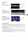
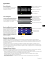
Tipos de pantalla
— Figura 12 —
Información
Las pantallas de información, como la pantalla HOME
(INICIO), están diseñadas para proporcionarle una buena
cantidad de información útil con un solo vistazo.
F1: A B C D
Full
+1.5 dB
A - FR
+1.5 dB
C - FR
Full
+1.5 dB
D - FR
Full
121 V 7.2 AAC Voltage: AC Current:
Home (Press HOME for more information)
+3.5 dB
B - FR
Full
Amp Status:
OK
N.º y configuración del preajuste
Ubicación y rutas de navegación
Configuración de canales y ganancia
Voltaje y corriente de CA
Estado del amplificador
— Figura 13 —
Preset Recall and Save
Menu
PRESETS
INPUTS
F1: A B C D
Navegación
Las pantallas de navegación proporcionan el medio para
desplazarse alrededor de los elementos del menú y
seleccionarlos. Utilice la perilla Master Control (Rueda de
control general), así como los botones ENTER (INTRO) y
EXIT (SALIR), para la navegación. Este es un ejemplo de un
tipo de pantalla de navegación; existen otros.
N.º y configuración del preajuste
Ubicación y rutas de navegación
Un área vacía indica que no se hicieron las selecciones
indicadas más arriba (hacia la izquierda).
Selección actual del menú
Selección siguiente del menú a continuación
(hacia la derecha)
— Figura 14 —
Edición de parámetros
Las pantallas de edición de parámetros le permiten
seleccionar, editar y confirmar cambios para diversos
parámetros del sistema. Utilice el botón ENTER (INTRO)
para editar y confirmar los cambios a los parámetros.
Utilice la perilla Master Control (Rueda de control general)
para seleccionar el parámetro y para hacer ajustes. Utilice
el botón EXIT (SALIR) para salir del modo de edición sin
guardar los cambios.
Gain
-7.0 dB
Gn/Pol
F1: A B C D
Polarity
POL+
Output
A
20 dB
-60 dB
Gain
-7.0 dB
Parámetro que se está editando
Parámetro no seleccionado
Parámetro seleccionado
Acerca de los preajustes
Los amplificadores PLD se controlan mediante preajustes. Para obtener el máximo provecho de los amplificadores, resulta esencial conocer bien cómo funcionan los
preajustes. Un preajuste, en el contexto de los amplificadores PLD, es una combinación de configuraciones del amplificador (entradas y salidas), y de asignaciones de
DSP y altavoces. Al recuperarse un preajuste, este podrá cambiar el enrutamiento y cableado de salida y cualquiera de los ajustes del DSP.
Los amplificadores PLD disponen de 20 preajustes de fábrica no modificables y de 50 preajustes definidos por el usuario. Los preajustes de fábrica están diseñados
como puntos de partida para crear los preajustes que usted necesite para su instalación en particular. Los preajustes de fábrica F1: hasta F9: no disponen de asignaciones
DSP ni de altavoces, solamente configuraciones de salida. Los preajustes de fábrica F10: hasta F20: incluyen ajustes básicos junto con las configuraciones de salida.
Prejustes definidos por el usuario
Los preajustes U1 a U50 están configurados de fábrica igual que el preajuste de fábrica F1. Cuando guarde un preajuste, este sobreescribirá uno de los preajustes
definidos por el usuario. Hay tres formas de crear preajustes definidos por el usuario.
• Puede cargar un preajuste definido por el usuario con la configuración de salida que desee, después modificar los parámetros DSP y GUARDARLO (SAVE)
sobreescribiendo el preajuste que cargó previamente, o bien puede escoger GUARDAR COMO (SAVE AS) (sobreescribir) otro preajuste definido por el usuario.
• Puede cargar un preajuste de fábrica, modificar sus parámetros, y después GUARDAR COMO (SAVE AS) uno de los preajustes definidos por el usuario. El proceso
de GUARDAR (SAVE) no está disponible para preajustes de fábrica
• Puede emplear el asistente para definir preajustes (Preset Wizard) para establecer la configuración de salida, la salida de potencia, y otros parámetros, y después
opte por GUARDAR COMO (SAVE AS) (sobreescribir) un preajuste definido por el usuario.

20
TD-000351-00-E
ES
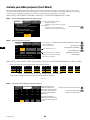
Asistente para definir preajustes (Preset Wizard)
El asistente para definir preajustes (Preset Wizard) simplifica el proceso de creación de preajustes, y le permite crear un preajuste sin utilizar otro como modelo.
El asistente para definir preajustes proporciona un mecanismo mediante el cual es posible seleccionar la potencia y carga deseadas. Basándose en estas selecciones,
se selecciona la mejor configuración del amplificador y a continuación se le permite seleccionar y asignar altavoces en cada salida.
HOME > PRESETS > PRESET WIZARD > ENTER (INICIO > PREAJUSTES > ASISTENTE PARA DEFINIR PREAJUSTES > INTRO)
PASO 1 —
Acerca del PRESET WIZARD (Asistente para definir preajustes)
ABOUT SPEAKERS SAVE
Preset Wizard does the following:
• Configures the amplifier
• Loads DSP settings for assigned speakers
Tips:
• Start with the highest power
• Speakers do not need to be assigned
to each output
NEXT
El asistente de preajustes realiza lo siguiente:
• Configura el amplificador
• Carga ajustes de DSP para los altavoces asignados
Recomendaciones:
• Empiece por la mayor cantidad de potencia
• Los altavoces no necesitan asignarse a cada salida
Para continuar, pulse
ENTER
PASO 2 —
Ajuste de la impedancia y la potencia
OUTPUTS SPEAKERS SAVE
A B C D
Output:
8.0 - - - - - -
Imped:
625 - - - - - -
Power:
Remaining Power Available: 1875 W
Enter Load Profile (Impedance and Power)
Ajuste la impedancia
en base a la carga total de
altavoces conectada al canal.
Valor predeterminado = 8 Ω
Valor predeterminado = mín. para el amp
La impedancia y la potencia están enlazadas
dinámicamente para los ajustes.
Desplácese para seleccionar (impedancia o potencia)
Para editar, pulse
Gire para ajustar el parámetro
Para confirmar, pulse
Repita para los canales de
salida restantes
ENTER
ENTER
HOME > PRESETS > PRESET WIZARD > ENTER > (ENTER) (INICIO > PREAJUSTES > ASISTENTE PARA DEFINIR PREAJUSTES > INTRO > [INTRO])
— Figura 15 —
- - -
B
25%
A
- - -
25%
D
- - -
25%
C
- - -
25%
AB
- - -
50%
D
- - -
25%
C
- - -
25%
CD
- - -
50%
AB
- - -
50%
A+B
- - -
50%
D
- - -
25%
C
- - -
25%
D
- - -
25%
ABC
- - -
75%
ABCD
- - -
100%
AB + CD
- - -
100%
A+B
- - -
50%
C+D
- - -
50%
*
Posibles combinaciones del modo de salida utilizando el asistente para definir preajustes
Modos: A B = Canales separados / A+B = Modo puenteado (Bridge) / AB = Modo paralelo
*Los porcentajes se utilizan para representar la potencia para diferentes modelos de amplificador.
PASO 3 —
Seleccionar el canal de salida para la asignación de altavoces
OUTPUTS SPEAKERS SAVE
Assign
AssignAssign
Output:
A DCB
Imped:
8.0 8.08.08.0
Spkr:
- - - - - - - -- - - -- - - -
Assign
Power:
625 625625625
Cuando haya terminado de
establecer la impedancia y la
potencia para cada salida, continúe
desplazándose hacia abajo para
acceder a la pestaña SPEAKERS
(ALTAVOCES).
La asignación de altavoces es
opcional; puede asignar un altavoz
a uno o más canales, o ninguno en
absoluto.
Desplácese para seleccionar el canal de salida.
Para asignar un altavoz, pulse
Continúe con el paso siguiente.
ENTER
La page est en cours de chargement...
La page est en cours de chargement...
La page est en cours de chargement...
La page est en cours de chargement...
La page est en cours de chargement...
La page est en cours de chargement...
La page est en cours de chargement...
La page est en cours de chargement...
La page est en cours de chargement...
La page est en cours de chargement...
La page est en cours de chargement...
La page est en cours de chargement...
La page est en cours de chargement...
La page est en cours de chargement...
La page est en cours de chargement...
La page est en cours de chargement...
La page est en cours de chargement...
La page est en cours de chargement...
La page est en cours de chargement...
La page est en cours de chargement...
La page est en cours de chargement...
La page est en cours de chargement...
La page est en cours de chargement...
La page est en cours de chargement...
La page est en cours de chargement...
La page est en cours de chargement...
La page est en cours de chargement...
La page est en cours de chargement...
La page est en cours de chargement...
La page est en cours de chargement...
La page est en cours de chargement...
La page est en cours de chargement...
La page est en cours de chargement...
La page est en cours de chargement...
La page est en cours de chargement...
La page est en cours de chargement...
La page est en cours de chargement...
La page est en cours de chargement...
La page est en cours de chargement...
La page est en cours de chargement...
La page est en cours de chargement...
La page est en cours de chargement...
La page est en cours de chargement...
La page est en cours de chargement...
La page est en cours de chargement...
La page est en cours de chargement...
La page est en cours de chargement...
La page est en cours de chargement...
La page est en cours de chargement...
La page est en cours de chargement...
La page est en cours de chargement...
La page est en cours de chargement...
La page est en cours de chargement...
La page est en cours de chargement...
La page est en cours de chargement...
La page est en cours de chargement...
La page est en cours de chargement...
La page est en cours de chargement...
La page est en cours de chargement...
La page est en cours de chargement...
La page est en cours de chargement...
La page est en cours de chargement...
La page est en cours de chargement...
La page est en cours de chargement...
-
 1
1
-
 2
2
-
 3
3
-
 4
4
-
 5
5
-
 6
6
-
 7
7
-
 8
8
-
 9
9
-
 10
10
-
 11
11
-
 12
12
-
 13
13
-
 14
14
-
 15
15
-
 16
16
-
 17
17
-
 18
18
-
 19
19
-
 20
20
-
 21
21
-
 22
22
-
 23
23
-
 24
24
-
 25
25
-
 26
26
-
 27
27
-
 28
28
-
 29
29
-
 30
30
-
 31
31
-
 32
32
-
 33
33
-
 34
34
-
 35
35
-
 36
36
-
 37
37
-
 38
38
-
 39
39
-
 40
40
-
 41
41
-
 42
42
-
 43
43
-
 44
44
-
 45
45
-
 46
46
-
 47
47
-
 48
48
-
 49
49
-
 50
50
-
 51
51
-
 52
52
-
 53
53
-
 54
54
-
 55
55
-
 56
56
-
 57
57
-
 58
58
-
 59
59
-
 60
60
-
 61
61
-
 62
62
-
 63
63
-
 64
64
-
 65
65
-
 66
66
-
 67
67
-
 68
68
-
 69
69
-
 70
70
-
 71
71
-
 72
72
-
 73
73
-
 74
74
-
 75
75
-
 76
76
-
 77
77
-
 78
78
-
 79
79
-
 80
80
-
 81
81
-
 82
82
-
 83
83
-
 84
84


QSC PLD4.2 Guide de démarrage rapide
- Catégorie
- Haut-parleurs de la barre de son
- Taper
- Guide de démarrage rapide
dans d''autres langues
- español: QSC PLD4.2 Guía de inicio rápido