Scott Living 1167FM-28-200 Guide d'installation
- Catégorie
- Chauffe-eau
- Taper
- Guide d'installation
Ce manuel convient également à

Français p. 19
Español p. 38
MODEL # 1167FM-28-200, 1167FM-28-201, 1167FM-28-202
ASSEMBLY, CARE & USE INSTRUCTIONS
ITEM # 0839833 / 0849091 / 0849092
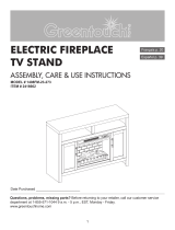
Media Mantel with
28-IN Infrared Electric
Fireplace
TM
Questions, problems, missing parts?
Before returning to your retailer,
call our customer service department at
1-855-571-1044 9 a.m. - 5 p.m., EST, Monday - Friday.
www.greentouchhome.com
Date Purchased _______________________

2
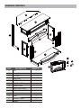
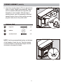
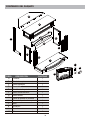
PACKAGE CONTENTS
PART DESCRIPTION QUANTITY
A Top
Corner Panel
1
B 1
C
Left Wall
1
D
Right Wall
Left Front Panel
Right Front Panel
1
E 1
1
F
G 1
H
1I
1
Base
J
1
K
Insert
1
L
Remote Control
1
M
Battery
2
Wood Door Panel
L Corner Support Rod
Center Panel
A
B
C
D
E
F
I
J
K
L
H
G
M

3
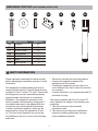
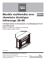
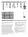
HARDWARE CONTENTS (NOT SHOWN ACTUAL SIZE)
PART DESCRIPTION QUANTITY
AA 25Long Bolt
BB Washer 25
CC Wooden Dowel
18
Insert Bracket
DD
2
EE Short Bolt
Touch-up Pen
6
FF Screw 4
GG 1
SAFETY INFORMATION
AA BB CC GGDD
EE FF
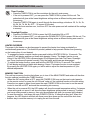
This device complies with Part 15 of the FCC
rules. Operation is subject to the following two
conditions:
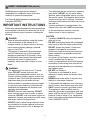
Please read and understand this entire manual
before attempting to assemble, operate or install
the product.
This equipment has been tested and found to
comply with the limits for Class B digital devices,
pursuant to Part 15 of the FCC rules. These limits
are designed to provide reasonable protection
against harmful interference in a residential
installation. The equipment generates, uses
and can radiate radio frequency energy and, if
not installed and used in accordance with the
instructions, may cause harmful interference
to radio or television reception, which can be
determined by turning the equipment off and
on. The user is encouraged to try and correct
the interference by one or more of the following
measures:
• Reorient or relocate the receiving antenna
• Increase the separation between the
equipment and the receiver
• Connect the equipment into an outlet on a
circuit different from that to which the receiver
is connected.
• Consult the dealer or an experienced radio/TV
technician for help.
1. This device may not cause harmful
interference, and
2. This device must accept any interference
received, including interference that may
cause undesired operation.

4
IMPORTANT INSTRUCTIONS
SAFETY INFORMATION (CONT’D)
DANGER
WARNING
This Class B digital apparatus complies with
Canadian ICES-003.
Modifications not approved by the party
responsible for compliance could void user’s
authority to operate the equipment.
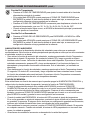
When using electrical appliances, basic precautions
should always be followed to reduce the risk of fire,
electric shock and injury to persons, including the
following:
• Read all instructions before using this heater.
• If the information in this manual is not
followed exactly, an electric shock or fire may
result causing property damage, personal
injury or loss of life.
• This product is intended to fit most plasma
and LCD televisions (up to 56 inches and
weighing a maximum of 60 pounds). Using
this item with loads heavier than the stated
maximum can result in tipping and/or
instability, which can result in injury or even
death.
• This appliance is hot when in use. To avoid
burns, DO NOT let bare skin touch hot
surfaces. Keep combustible material, such as
furniture, pillows, bedding, papers, clothes and
curtains at least 3 feet from this appliance and
keep them away from the sides and rear.
• Extreme caution is necessary when any heater
is used by or near children or individuals with
disabilities and whenever the fireplace is left
operating and unattended.
• DO NOT run cord under carpeting. DO NOT
cover cord with throw rugs, runners, or similar
coverings. DO NOT route cord under funiture or
appliances. Arrange cord away from traffic areas
and where it will not be tripped over.
• DO NOT insert or allow foreign objects to enter
any ventilation or exhaust opening as this may
cause an electric shock or fire, or damage the
appliance.
• This appliance has hot and arcing or sparking
parts inside. DO NOT use it in areas where
gasoline, paint or flammable vapors or liquids
are used or stored. This fireplace should not be
used as a drying rack for clothing. Christmas
stockings or decorations should not be hung in
the area of it.
• Use this appliance only as described in the
manual. Any other use is NOT recommended
by the manufacturer and may cause fire,
electric shock or injury to persons.
• If possible, ALWAYS unplug this appliance
when not in use.
• DO NOT operate any heater with a damaged
cord or plug or after the heater malfunctions.
DO NOT operate any heater if it has been
dropped or damaged in any manner.
Disconnect power at service panel and have
heater inspected by a reputable electrician
before reusing.
• Any repairs to this fireplace should be carried
out by a qualified service person.
• Under no circumstances should this fireplace
be modified. Parts having to be removed for
servicing must be replaced prior to operating
this fireplace again.
• DO NOT use outdoors.
• This heater is not intended for use in
bathrooms, laundry areas and similar indoor
locations.
NEVER place heater where it may fall into a
bathtub or other water container.
• To disconnect this appliance, turn controls to
the off position, then remove plug from outlet.
• ONLY connect to properly grounded outlets.
• This appliance, when installed, must be
electrically grounded in accordance with local
codes, with the current CSA C22.1 Canadian
Electrical Code or follow U.S.A. Installations,
follow local codes and the National Electrical
Code, ANSI/NFPA N0.70.
CAUTION

5
SAVE THESE INSTRUCTIONS
SAFETY INFORMATION (CONT’D)
A B C D
Grounding Pin Grounding Pin
Grounding Means
Metal
Screw
Cover of
Grounding
Box
Adapter
Electrical Connection
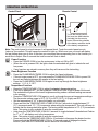
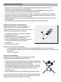
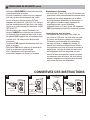
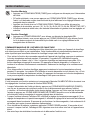
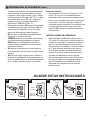
Grounding Instructions
• To prevent a possible fire, DO NOT block
air intakes or exhaust in any manner. DO
NOT use on soft surfaces, like a bed, where
opening may become blocked.
• The heaters MUST NOT be located
immediately below a socket-outlet.
• ALWAYS plug heaters directly into a wall
outlet/receptacle. NEVER use with an
extension cord or re-loadable power tap (outlet
/ power strip).
• DO NOT slide insert on top of wood to avoid
scratching wood surface.
• DO NOT place any object on top of the insert
or block the air intakes / vents as this can
cause the unit to overheat and could cause
a fire.
• A 15-Amp, 120-volt, 60 Hz circuit with
a properly grounded outlet is required.
Preferably, the fireplace will be on a dedicated
circuit as other appliances on the same circuit
may cause the circuit breaker to trip or the
fuse to blow when the heater is in operation.
The unit comes standard with 6-ft. three-wire
cord, exiting from the rear of the fireplace.
DO NOT exceed the current rating of the
current tap.
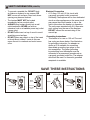
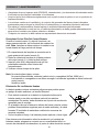
• This heater is for use on 120 volt.The cord
has a plug as shown below. See illustration
for grounding instruction. An adapter as
shown at C is available for connecting
three-blade grounding type plugs to two-
slot receptacles. The green grounding
lug extending from the adapter must be
connected to a permanent ground such as
a properly grounded outlet box. The adapter
should not be used if a three-slot grounded
receptacle is available.

6
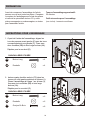
PREPARATION
ASSEMBLY INSTRUCTIONS
Hardware Used
Hardware Used
long bolt
long bolt
washer
washer
wooden dowel
x 4
x 6
x 4
x 6
x 8
AA
AA
BB
BB
CC
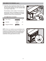
1.
2.
Repeat for right wall (D)
1
F
E
2
C
D
BB
AA
1
BB
CC
AA
C
J
2
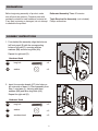
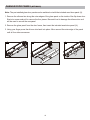
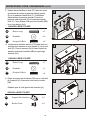
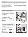
Insert four wooden dowels (CC) into holes on
left outer side of base (J). Place assembly from
Step 1 onto base (J), securing with three
washers (BB) and three long bolts (AA).
Repeat for right wall (D).
From behind the assemblyalign the holes on
left front panel (E) with the corresponding
holes on left wall (C). securing with two
washers (BB) and two long bolts (AA).
Estimated Assembly Time: 50 minutes
Before beginning assembly of product, make
sure all parts are present. Compare parts with
package contents list and hardware contents list.
If any part is missing or damaged, do not attempt
to assemble the product.
Tools Required for Assembly (not included):
Phillips screwdriver

7
ASSEMBLY INSTRUCTIONS (CONT’D)
Hardware Used
long bolt
washer
wooden dowel
x 2
x 2
x 2
AA
BB
CC
4.
4
Hardware Used
long bolt
washer
wooden dowel
x 7
x 7
x 4
AA
BB
CC
3
G
5
1
Hardware Used
insert bracket
x 2
DD
short bolt
x 6
EE
BB
CC
AA
FF
GG
K
A
BB
CC
AA
1
2
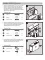
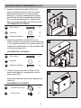
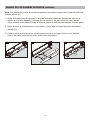
Insert two wooden dowels (CC) into the top outer
holes on both left wall (C) and right wall (D). Attach
top (A), securing from underneath with seven
washers (BB) and seven long bolts (AA).
3. Insert two wooden dowels (CC) into the top middle
holes on both left front panel (E) and right front
panel (F). Carefully position the center panel (G)
into place between left front panel (E) and right
front panel (F). Secure each side with one washer
(BB) and one long bolt (AA).
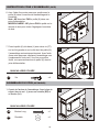
5. Locate the Insert bracket (DD) on the right side of
the insert (K), securing with three short bolts (EE).
Repeat for the left side of the insert (K).

8
ASSEMBLY INSTRUCTIONS (CONT’D)
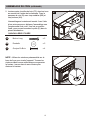
CORNER ASSEMBLY (OPTIONAL)
Hardware Used
x 4
FF
7
screw
6
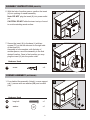
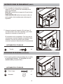
1. From behind the assembly, Attach L corner support
rod (I), secure with one washer (BB) and one bolt
(AA).
1
Hardware Used
long bolt
washer
x 1
x 1
AA
BB
I
AA
BB
K
DD
6. With the help of another person, position the insert
(K) into opening of mantel assembly.
Note: DO NOT plug the insert (K) into power outlet
yet.
CAUTION: DO NOT slide the insert on top of wood
to avoid scratching wood surface.
7. Secure the insert (K) to the base (J) with two
screws (FF) on the left side and on the right side
of the insert (K).
Assembly is now complete, with the help of
another person, move the assembly to the final
desired location. Once in final position you may
plug the insert (K) into the power outlet.

9
CORNER ASSEMBLY (CONT’D)
2
Hardware Used
long bolt
washer
wooden dowel
x 5
x 5
x 4
AA
BB
CC
AA
BB
CC
B
2. Insert four wooden dowels (CC) into the top back
holes of mantel, Attach corner panel (B), secure
with five washers (BB) and five long bolts (AA).
Assembly is now complete. With the help of
another person, move the assembly to the final
desired location. Once in final position you may
plug the insert (K) into the power outlet.
NOTE: Use the pre-assembled levelers on the base
of the fireplace to level the unit. Twist the levelers
counter clockwise to increase the height, twist the
clockwise to decrease the height.

10
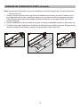
CHANGE DOOR PANELS (OPTIONAL)
Note: The pre-installed glass door panels can be switched out with the included wood door panel (H).
1. Remove the silicone trim along the outer edges of the glass panel on the inside of the flip down door.
Start at a corner and pull to remove the four pieces. Be careful not to damage the silicone trim as it
will be used to secure the new panel.
2. Remove the glass panel from the door frame, then insert the included wood door panel (H).
3. Using your finger press the silicone trim back into place. Move around the outer edge of the panel
until all four sides are secure.
2
4
3
1
1
2
3
4
1
3
2
H

11
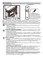
OPERATING INSTRUCTIONS
Power Function
Flame Brightness Function
Temperature Function
M
M
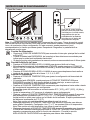
To use the remote control,
first insert two AAA batteries
(included) into the remote
control. Ensure the polarities
of the battery match the inside
of the battery compartment.
Note: The control panel is a touch screen. It will appear black. Touch the control panel once to
“wake up” the controls. This will cause the controls to light up. Which ever icon you touch will display
it’s last setting when you do this. At this time you can press the corresponding icon to the function you
would like to adjust. After 5 seconds the touch screen will fade to black.
• Press the TEMPERATURE ICON to adjust the heater’s thermostat setting.
• If the unit is powered OFF, you can press the TEMPERATURE ICON to power ON the unit.
The emberbed will glow at the lowest brightness setting unless a different setting was saved
in the memory.
• Press the TEMPERATURE ICON again to scroll up through the pre-set temperature settings:
The thermostat setting range is 65°F (18°C) to 90ºF (32°C), HI (High) and OFF.
• Set the temperature to "HI" to have the heater run continually.
• Press and hold the TEMPERATURE & TIMER ICON for 5 seconds to toggle between 5°F
(3°C) increments and 1ºF (1°C) increments when setting the temperature. The unit will beep to
indicate that the change has taken place. The factory default temperature is 5°F (3°C) increments.
Note: This option is only available if using the control panel.
• Hold down the TEMPERATURE ICON for 5 seconds to toggle between Fahrenheit and Celsius.
An “F” or “C” will display next to the temperature.
Note: This option is only available if using the control panel.
• Press and hold the TEMPERATURE ICON for 10 seconds to disengage the heater function.
Press and hold the TEMPERATURE ICON for 10 seconds again to engage the heater
function. (See HEATER OVERRIDE section below for more details).
• Press the POWER ICON to turn the main power to the unit ON or OFF.
• When the unit is powered ON, the lights under the emberbed will glow to indicate the unit
has power.
• If any functions are stored in memory then they will resume at the last setting .
• Press the FLAME BRIGHTNESS ICON to adjust the flame brightness.
• If the unit main power is OFF, you can press the FLAME BRIGHTNESS ICON to power ON
the unit and flame brightness will resume at the last setting.
• Press the FLAME BRIGHTNESS ICON again to scroll up through the flame brightness
settings: 1, 2, 3, 4, 5, OFF.
Control Panel Remote Control

OPERATING INSTRUCTIONS (CONT’D)
12
Timer Function
Downlight Function
MEMORY FUNCTION
HEATER OVERRIDE
• Press the TIMER ICON to set the countdown for the unit’s main power.
• If the unit is powered OFF, you can press the TIMER ICON to power ON the unit. The
emberbed will glow at the lowest brightness setting unless a different setting was saved in
the memory.
• Press the TIMER ICON again to scroll through the timer settings, which are: 30, 1h, 2h, 3h,
4h, 5h, 6h, 7h, 8h, 9h, OFF.30 means 30 minutes)
• When the timer reaches zero, it will turn OFF the main power and will maintain all the settings
in memory.
The power to the heater can be disengaged to prevent the heater from being accidentally or
unintentionally powered on. This feature is primarily added to help prevent children from powering
on the heater when it is not desired.
• To engage the heater override function press and hold the HEATER ICON for 10 seconds. The
symbol E3 will display and then go blank while beeping 3 times. The heater function is now
locked. If the HEATER ICON is pressed again E3 will appear then fade.The Flame, Downlight
and Timer functions will operate normally. Only the heater and blower are disengaged.
• To unlock the heater function, press and hold the HEATER ICON for 10 seconds. The symbol
E3 will display and then go blank while beeping 3 times. The heater function is now engaged.
By pressing the HEATER ICON again you will be able to adjust the heat temperature to your
desired temperature.
• Press the DOWNLIGHT ICON to power the LED downlights ON or OFF
• If the unit is powered OFF, you can press the DOWNLIGHT ICON to power ON the unit. The
emberbed will glow at the lowest brightness setting unless a different setting was saved in
the memory.
This unit has a memory function that allows you to turn off the MAIN POWER and retains all the other
function settings (excluding the TIMER function).
• When the unit’s main power is OFF, press the POWER ICON once on the insert control panel or
on the remote control to power the unit ON and “wake up” the individual function at the last setting.
Press the icon again to adjust it and press the main POWER ICON on the insert or on the remote
control to turn the unit OFF and save the new setting into memory.
• When the unit is powered ON, the LED readout will show the saved temperature setting. If a temper
-ature setting was not saved, it will show the flame brightness setting saved in memory. If neither
one has a setting saved to memory, then only the emberbed will glow (as a power light indicator).
• To reset the memory, hold down the main POWER ICON for 10 seconds at any time. When this
happens, the LED readout will blink with three zeros three times and the unit will be shut down.
• Another way to reset the memory is to unplug the unit from the wall.

CARE AND MAINTENANCE
13
Disposal of Used Battery
Replacing the Remote Control Batteries
L
• Make sure the unit is turned OFF, unplugged and the heating elements of heater are cool
whenever you are cleaning the heater or fireplace.
• Clean the metal trim using a water-dampened soft, clean cloth. DO NOT use brass polish or
household cleaners as these products will damage the metal trim.
• The motors used on the fan and the flame generator assembly are pre-lubricated for extended
bearing life and require no further lubrication. However, periodic cleaning/vacuuming of the fan/
heater and air intake/output vents is recommended.
• When the heater is not in use, the power cord should be stored properly to avoid contact with hot
or sharp objects.
• Any other servicing should be performed by an authorized service representative.
When the remote control (L) stops operating or its
range seems reduced, it is time to replace the
batteries. Note:The batteries should be removed if the
product is to be left unused for a long time.
1. The battery compartment is located on the back
of the remote control (L).
2. Remove battery cover from the back of remote
control (L) and remove the old batteries.
3. Insert 2pcs AAA batteriesensuring the polaritie s of
the battery match the inside of the battery
compartment.
4. Re-insert the battery door.
Note: Do not mix old and new batteries.
Do not mix alkaline, standard (carbon zinc), or rechargeable (nicad, nimh, etc) batteries.
Non-rechargeable batteries are not to be recharged. Exhausted batteries are to be removed from
the product.
Harmful if swallowed.
A battery may contain hazardous substances that could be
endangering the environment and human health.
• This symbol marked on the battery and/or packaging indicates that
used battery shall not be treated as municipal waste. Instead it shall
be left at the appropriate collection point for recycling.
• By ensuring the used battery is disposed of correctly, you will help
prevent potential negative consequences for the environment and
human health. The recycling of materials will help to conserve
natural resources.
• Do not dispose of batteries in fire. batteries may explode or leak.
For more information about collection and recycling of used batteries,
please contact your local municipality, your waste disposal service or
the point-of-sale where you purchased this battery.

14
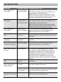
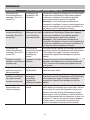
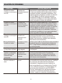
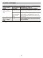
PROBLEM POSSIBLE CAUSE CORRECTIVE ACTION
TROUBLESHOOTING
Error E1 displayed on
control panel.
Error E2 displayed on
control panel.
Error E3 displayed on
control panel.
Heater override
function is engaged
No power; logs do not
glow.
The unit does not
have power.
No flame effect but logs
are glowing.
The flame effect is
powered off.
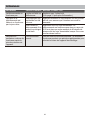
Power cord gets warm to
the touch.
Normal operation.
Remote control does not
work.
Replace with 2 AAA batteries. (See page 13 for more
information.)
Press the buttons slowly and steadily to ensure the
transmitter recognizes the request.
Normal operation. This is a standard feature; the blower runs for an
additional time to cool off heater tubes.
Heater override
function is engaged
Heater and blower
do not power on but rest
of functions are working.
The overheat sensor
has been engaged.
The thermostat
sensor is broken or
not working correctly.
Remote control
signal is weak and only
works sometimes.
Fan motor continues to
blow after unit is powered
off.
Using the remote
control too far away or
at an off angle.
Pressing the buttons
too quickly.
Weak or failing
batteries.
Unplug unit, wait 15-20 minutes, then the sensor will reset
itself. Plug the unit back in and turn on the heater. If the
problem persists, call customer service.
Note: The other functions will work normally excluding
the heater. Until the problem is solved, the error will only
appear/sound when the heater button is pressed.
To unlock the heater, simply press and hold the
temperature button for 10 seconds (See page 12
Heater Override Section for more details).
Check that the power cord is securely plugged into a
standard 120V outlet. Then check to make sure the unit is
powered on.
Push the flame brightness button until desired level is
achieved.
To unlock the heater, simply press and hold the
temperature button for 10 seconds (See page 12
Heater Override Section for more details).
This is normal for a heater appliance as it requires
more current to operate. Check the connections of
the appliance cord and the outlet. Make sure the plug
fits tightly into the outlet. During use, check the plug
and outlet frequently to determine if it is HOT; if so,
discontinue use of the appliance and consult with a
qualified electrician to check or change the overheating
outlet(s).
Move closer to the insert; the remote control will only
work within a distance of 20 feet and 45 degrees to either
side from the front of the fireplace insert.

15
ONE-YEAR LIMITED WARRANTY
The manufacturer warrants that your new Electric fireplace is free from manufacturing and material
defects for a period of one year from date of purchase, subject to the following conditions and
limitations.
Install and operate this Electric fireplace in accordance with the installation and operating instructions
furnished with the product at all times. Any unauthorized repair, alteration, willful abuse, accident, or
misuse of the product shall nullify this warranty.
This warranty is non-transferable, and is made to the original owner, provided that the purchase was
made through an authorized supplier of the product.
The warranty is limited to the repair or replacement of part(s) found to be defective in material or
workmanship, provided that such part(s) have been subjected to normal conditions of use and
service, after said defect is confirmed by the manufacturer’s inspection.
The manufacturer may, at its discretion, fully discharge all obligations with respect to this warranty by
refunding the wholesale price of the defective part(s).
Any installation, labor, construction, transportation, or other related costs/expenses arising from
defective part(s), repair, replacement, or otherwise of same, will not be covered by this warranty, nor
shall the manufacturer assume responsibility for same.
The owner/user assumes all other risks, if any, including the risk of any direct, indirect or
consequential loss or damage arising out of the use, or inability to use the product, except as
provided by law.
All other warranties-expressed or implied-with respect to the product, its components and
accessories, or any obligations/liabilities on the part of the manufacturer are hereby expressly
excluded.
The manufacturer neither assumes, nor authorizes any third party to assume on its behalf, any other
liabilities with respect to the sale of the product.
The warranties as outlined within this document do not apply to non accessories used in conjunction
with the installation of this product.
This warranty is void if:
1. The fireplace is subjected to prolonged periods of dampness or condensation.
2. Any unauthorized alteration, willful abuse, accident, or misuse of the product.
3. You do not have the original receipt of purchase.

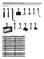
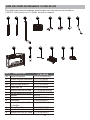
PART DESCRIPTION PART #
HH
REPLACEMENT PARTS FOR 1167FM-28-200
H
L M N O PK
JJ
II
KK LL
II
JJ
KK
LL
H
Insert
Wood Door Panel
Finger Pull With Screws
Hardware Packet PH17-1167FM-28-200
Flip Door Hinge PU17-1167FM-001
Door Catch PU17-1167FM-002
PU17-1167FM-003
PU17-1167FM-004
PF-1167FM-28-200-001
PF-1167FM-28-200-002
Piston With Screw
L Corner Support Rod
M
I
Q
I
16
Spinner Motor
PU16-23262833-HB
PCB Board PU16-262833-PCB
Glass Door Panel PF-1167FM-28-001
PU16-23262833-SM
Heater/Blower
Assembly
PU16-232628-NTC
Remote Control
Thermostat
PU16-262833-RC
N
K
L
O
P
Q
2812-FG
HH
For replacement parts, call our customer service department at 1-855-571-1044, 9 a.m. - 5 p.m., EST,
Monday - Friday.

HH
REPLACEMENT PARTS FOR 1167FM-28-201
II
JJ
KK
LL
H
Insert
Wood Door Panel
Finger Pull With Screws
Hardware Packet PH17-1167FM-28-201
Flip Door Hinge PU17-1167FM-001
Door Catch PU17-1167FM-002
PU17-1167FM-003
PU17-1167FM-004
PF-1167FM-28-201-001
PF-1167FM-28-201-002
Piston With Screw
L Corner Support Rod
M
I
17
Spinner Motor
PU16-23262833-HB
PCB Board PU16-262833-PCB
Glass Door Panel PF-1167FM-28-001
PU16-23262833-SM
PU16-232628-NTC
Remote Control
Thermostat
PU16-262833-RC
N
K
L
O
P
Q
2812-FG
H
L M N O PK
JJ
II
KK LL
Q
I
HH
PART DESCRIPTION PART #
Heater/Blower
Assembly
For replacement parts, call our customer service department at 1-855-571-1044, 9 a.m. - 5 p.m., EST,
Monday - Friday.

HH
REPLACEMENT PARTS FOR 1167FM-28-202
II
JJ
KK
LL
H
Insert
Wood Door Panel
Finger Pull With Screws
Hardware Packet PH17-1167FM-28-202
Flip Door Hinge PU17-1167FM-001
Door Catch PU17-1167FM-002
PU17-1167FM-003
PU17-1167FM-004
PF-1167FM-28-202-001
PF-1167FM-28-202-002
Piston With Screw
L Corner Support Rod
M
I
18
Spinner Motor
PU16-23262833-HB
PCB Board PU16-262833-PCB
Glass Door Panel PF-1167FM-28-001
PU16-23262833-SM
PU16-232628-NTC
Remote Control
Thermostat
PU16-262833-RC
N
K
L
O
P
Q
2812-FG
H
L M N O PK
JJ
II
KK LL
Q
I
HH
PART DESCRIPTION PART #
Heater/Blower
Assembly
For replacement parts, call our customer service department at 1-855-571-1044, 9 a.m. - 5 p.m., EST,
Monday - Friday.

English p. 1
Español p. 38
MODÈLE # 1167FM-28-200, 1167FM-28-201, 1167FM-28-202
INSTRUCTIONS D’UTILISATION, D’ASSEMBLAGE ET DE
MAINTENANCE
ARTICLE # 0839833 / 0849091 / 0849092
TM
Meuble multimédia avec
cheminée électrique
infrarouge 28-IN
Date d’achat _______________________
Des questions, des problèmes, des pièces manquantes?
Avant de retourner l’article au détaillant,
appelez notre service à la clientèle au
1-855-571-1044, entre 9 h et 17 h (HNE), du lundi au vendredi.
www.greentouchhome.com

20
CONTENU DE L’EMBALLAGE
A
B
C
D
E
F
I
J
K
L
H
G
PIÈCE DESCRIPTION QUANTITÉ
A Dessus 1
B 1
C Cloison gauche 1
D Cloison droite 1
E 1
1F
G 1
H
1I
1BaseJ
K Foyer encastrable 1
L Télécommande 1
M Pile 2
Panneau de coin
Panneau avant gauche
Panneau avant droit
Panneau de porte en bois
1
Panneau central
Tige de support de coin en L
M
La page est en cours de chargement...
La page est en cours de chargement...
La page est en cours de chargement...
La page est en cours de chargement...
La page est en cours de chargement...
La page est en cours de chargement...
La page est en cours de chargement...
La page est en cours de chargement...
La page est en cours de chargement...
La page est en cours de chargement...
La page est en cours de chargement...
La page est en cours de chargement...
La page est en cours de chargement...
La page est en cours de chargement...
La page est en cours de chargement...
La page est en cours de chargement...
La page est en cours de chargement...
La page est en cours de chargement...
La page est en cours de chargement...
La page est en cours de chargement...
La page est en cours de chargement...
La page est en cours de chargement...
La page est en cours de chargement...
La page est en cours de chargement...
La page est en cours de chargement...
La page est en cours de chargement...
La page est en cours de chargement...
La page est en cours de chargement...
La page est en cours de chargement...
La page est en cours de chargement...
La page est en cours de chargement...
La page est en cours de chargement...
La page est en cours de chargement...
La page est en cours de chargement...
La page est en cours de chargement...
La page est en cours de chargement...
-
 1
1
-
 2
2
-
 3
3
-
 4
4
-
 5
5
-
 6
6
-
 7
7
-
 8
8
-
 9
9
-
 10
10
-
 11
11
-
 12
12
-
 13
13
-
 14
14
-
 15
15
-
 16
16
-
 17
17
-
 18
18
-
 19
19
-
 20
20
-
 21
21
-
 22
22
-
 23
23
-
 24
24
-
 25
25
-
 26
26
-
 27
27
-
 28
28
-
 29
29
-
 30
30
-
 31
31
-
 32
32
-
 33
33
-
 34
34
-
 35
35
-
 36
36
-
 37
37
-
 38
38
-
 39
39
-
 40
40
-
 41
41
-
 42
42
-
 43
43
-
 44
44
-
 45
45
-
 46
46
-
 47
47
-
 48
48
-
 49
49
-
 50
50
-
 51
51
-
 52
52
-
 53
53
-
 54
54
-
 55
55
-
 56
56


Scott Living 1167FM-28-200 Guide d'installation
- Catégorie
- Chauffe-eau
- Taper
- Guide d'installation
- Ce manuel convient également à
dans d''autres langues
Documents connexes
Autres documents
-
Allen + Roth 2317FM-33-202 Guide d'installation
-
-
 GreenTouch 2416662 Guide d'installation
-
-
 Homestar ZCLARINGTN Manuel utilisateur
-
Mr. Heater 1008ST-24-102 Guide d'installation
-
ClassicFlame 39EB364GRS Mode d'emploi
-
Twin-Star International 23IMM1895 Manuel utilisateur
-
 GreenTouch 1164FM-23-202 Guide d'installation
-


