ESAB iCNC Performance CNC Controller Manuel utilisateur
- Catégorie
- Système de soudage
- Taper
- Manuel utilisateur

Thermal-Dynamics.com
®
24V
DC
INPUT VOLTAGE
Revision: AB Issue Date: February, 2016 Manual No.: 0-5401
iCNC PERFORMANCE
CNC CONTROLLER
Service and
Installation
Manual

WE APPRECIATE YOUR BUSINESS!
Congratulations on your new Thermal Dynamics product. We are proud to have you as our
customer and will strive to provide you with the best service and reliability in the industry. This
product is backed by our extensive warranty and world-wide service network. To locate your
nearest distributor or service agency call 1-800-752-7622, or visit us on the web at www.thermal-
dynamics.com.
This Service Manual has been designed to instruct you on the correct use and operation of your
Thermal Dynamics product. Your satisfaction with this product and its safe operation is our
ultimate concern. Therefore please take the time to read the entire manual, especially the Safety
Precautions. They will help you to avoid potential hazards that may exist when working with this
product.
YOU ARE IN GOOD COMPANY!
The Brand of Choice for Contractors and Fabricators Worldwide.
Thermal Dynamics is a Global Brand of manual and automation Plasma Cutting Products.
We distinguish ourselves from our competition through market-leading, dependable products
that have stood the test of time. We pride ourselves on technical innovation, competitive prices,
excellent delivery, superior customer service and technical support, together with excellence in
sales and marketing expertise.
Above all, we are committed to developing technologically advanced products to achieve a safer
working environment within the welding industry.

!
WARNING
Read and understand this entire Manual and your employer’s safety practices before installing, operat-
ing, or servicing the equipment.
While the information contained in this Manual represents the Manufacturer’s best judgement, the
Manufacturer assumes no liability for its use.
iCNC Performance
Service Manual No. 0-5401
Published by:
Thermal Dynamics Corporation.
2800 Airport Rd.
Denton, Texas 76207
www.thermal-dynamics.com
© Copyright 2015, 2016 by
Thermal Dynamics Corporation.
All rights reserved.
Reproduction of this work, in whole or in part, without written permission of the publisher is prohibited.
The publisher does not assume and hereby disclaims any liability to any party for any loss or damage caused by any er-
ror or omission in this manual, whether such error results from negligence, accident, or any other cause.
Publication Date: September 25, 2015
Revision Date: February, 2016
Record the following information for Warranty purposes:
Where Purchased: ___________________________________
Purchase Date:______________________________________
iCNC Performance Serial #:_______________________________

Be sure this information reaches the operator.
You can get extra copies through your supplier.
CAUTION
These INSTRUCTIONS are for experienced operators. If you are not fully familiar with the
principles of operation and safe practices for arc welding and cutting equipment, we urge
you to read our booklet, “Precautions and Safe Practices for Arc Welding, Cutting, and
Gouging,” Booklet 0-5407. Do NOT permit untrained persons to install, operate, or maintain
this equipment. Do NOT attempt to install or operate this equipment until you have read
and fully understand these instructions. If you do not fully understand these instructions,
contact your supplier for further information. Be sure to read the Safety Precautions before
installing or operating this equipment.
USER RESPONSIBILITY
This equipment will perform in conformity with the description thereof contained in this manual and accompanying labels and/or
inserts when installed, operated, maintained and repaired in accordance with the instructions provided. This equipment must be
checked periodically. Malfunctioning or poorly maintained equipment should not be used. Parts that are broken, missing, worn,
distorted or contaminated should be replaced immediately. Should such repair or replacement become necessary, the manufac-
turer recommends that a telephone or written request for service advice be made to the Authorized Distributor from whom it was
purchased.
This equipment or any of its parts should not be altered without the prior written approval of the manufacturer. The user of this
equipment shall have the sole responsibility for any malfunction which results from improper use, faulty maintenance, damage,
improper repair or alteration by anyone other than the manufacturer or a service facility designated by the manufacturer.
!
READ AND UNDERSTAND THE INSTRUCTION MANUAL BEFORE INSTALLING OR
OPERATING.
PROTECT YOURSELF AN D OTHERS!

ASSUREZ-VOUS QUE CETTE INFORMATION EST DISTRIBUÉE À L’OPÉRATEUR.
VOUS POUVEZ OBTENIR DES COPIES SUPPLÉMENTAIRES CHEZ VOTRE FOURNISSEUR.
ATTENTION
Les INSTRUCTIONS suivantes sont destinées aux opérateurs qualiés seulement. Si vous
n’avez pas une connaissance approfondie des principes de fonctionnement et des règles
de sécurité pour le soudage à l’arc et l’équipement de coupage, nous vous suggérons de
lire notre brochure « Precautions and Safe Practices for Arc Welding, Cutting and Gouging,
» Brochure 0-5407. Ne permettez PAS aux personnes non qualiées d’installer, d’opérer ou
de faire l’entretien de cet équipement. Ne tentez PAS d’installer ou d’opérer cet équipement
avant de lire et de bien comprendre ces instructions. Si vous ne comprenez pas bien les
instructions, communiquez avec votre fournisseur pour plus de renseignements. Assu-
rez-vous de lire les Règles de Sécurité avant d’installer ou d’opérer cet équipement.
RESPONSABILITÉS DE L’UTILISATEUR
Cet équipement opérera conformément à la description contenue dans ce manuel, les étiquettes d’accompagnement et/ou les
feuillets d’information si l’équipement est installé, opéré, entretenu et réparé selon les instructions fournies. Vous devez faire une
vérication périodique de l’équipement. Ne jamais utiliser un équipement qui ne fonctionne pas bien ou n’est pas bien entretenu.
Les pièces qui sont brisées, usées, déformées ou contaminées doivent être remplacées immédiatement. Dans le cas où une répa-
ration ou un remplacement est nécessaire, il est recommandé par le fabricant de faire une demande de conseil de service écrite ou
par téléphone chez le Distributeur Autorisé de votre équipement.
Cet équipement ou ses pièces ne doivent pas être modiés sans permission préalable écrite par le fabricant. L’utilisateur de l’équi-
pement sera le seul responsable de toute défaillance résultant d’une utilisation incorrecte, un entretien fautif, des dommages, une
réparation incorrecte ou une modication par une personne autre que le fabricant ou un centre de service désigné par le fabricant.
!
ASSUREZ-VOUS DE LIRE ET DE COMPRENDRE LE MANUEL D’UTILISATION AVANT
D’INSTALLER OU D’OPÉRER L’UNITÉ.
PROTÉGEZ-VOUS ET LES AUTRES!

This Page Intentionally Blank

Declaration of Conformity
We Thermal Dynamics
of 2800 Airport Road
Denton, TX 76207 U.S.A.
in accordance with the following Directive(s):
2006/95/EC The Low Voltage Directive
2004/108/EC The Electromagnetic Compatibility Directive
hereby declare that:
Equipment: Plasma Cutting CNC Controller
Model Name/Number: iCNC Performance
Market Release Date: August 19, 2015
is in conformity with the applicable requirements of the following harmonized standards:
Conforms to requirements of IEC 61326-1:2012
IEC 61000-4-2: 2008, Electro Static Discharge Immunity
IEC 61000-4-3:2006 +A1:2007 +A2:2010, Radiated, Radio-Frequency, Electromagnetic Immunity
IEC 61000-4-4:2012, Electrical Fast Transient/Burst Immunity
IEC 61000-4-6: 2008, Conducted Radio-Frequency Electromagnetic Immunity
IEC 61000-4-8:2009, Power Frequency Magnetic Field Immunity
CISPR 11:2009 +A1:2010, AC Mains Conducted Emissions
CISPR 11:2009 +A1:2010, Radiated Emissions
Meets IEC 61010-1:2010 Safety requirements for electrical equipment for measurement, control, and
laboratory use - Part 1: General requirements
Classification: The equipment described in this document is Class A and intended for industrial use.
!
WARNING
This Class A equipment is not intended for use in residential locations where the electrical
power is provided by the public low-voltage supply system. There may be potential difficul-
ties in ensuring electromagnetic compatibility in those locations, due to conducted as well
as radiated disturbances.
Manufacturer’s Authorized Representative
Steve Ward V.P. Europe and General Manager
Address:Victor Technologies International Inc.
Europa Building
Chorley N Industrial Park
Chorley, Lancashire,
England PR6 7BX
Date: August 19, 2015
Steve Ward
Full Name
V.P. Europe and General Manager
(Position)
(Signature)

!
WARNING
This Class A equipment is not intended for use in residential locations where the electrical
power is provided by the public low-voltage supply system. There may be potential difficul-
ties in ensuring electromagnetic compatibility in those locations, due to conducted as well
as radiated disturbances.

TABLE OF CONTENTS
SECTION 1: SAFETY ........................................................................................ 1-1
1.01 Safety Precautions - ENGLISH ........................................................................ 1-1
1.02 Précautions de sécurité - FRENCH CANADIAN ............................................... 1-6
SECTION 2: SPECIFICATIONS ............................................................................. 2-1
2.1 System Description ......................................................................................... 2-1
2.2 Specification ................................................................................................... 2-1
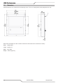
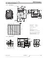
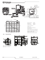
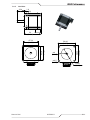
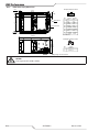
2.3 Dimensions ..................................................................................................... 2-2
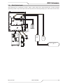
2.4 Basic System Layout ...................................................................................... 2-3
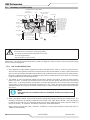
2.5 Grounding and Cable Routing ......................................................................... 2-4
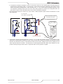
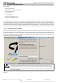
2.5.1 Low Cost Ground Rod Tester ......................................................................... 2-4
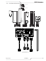
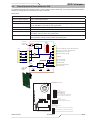
2.6 Connector Locations ....................................................................................... 2-6
SECTION 3: I/O DESCRIPTIONS .......................................................................... 3-1
3.1 General ........................................................................................................... 3-1
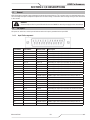
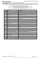
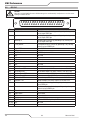
3.2 J45 Inputs ....................................................................................................... 3-1
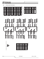
3.2.1 Input Pin Arrangement .................................................................................... 3-1
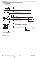
3.2.2 Input Example ................................................................................................. 3-2
3.2.3 Input Naming .................................................................................................. 3-2
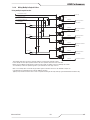
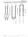
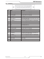
3.3 J46 Outputs .................................................................................................... 3-3
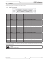
3.3.1 Output Pin Arrangement ................................................................................. 3-3
3.3.2 Output Example .............................................................................................. 3-4
3.3.3 Output naming ................................................................................................ 3-4
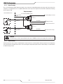
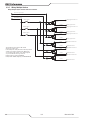
3.3.4 Wiring Multiple Oxyfuel Lifters ....................................................................... 3-5
3.3.5 Wiring Multiple Stations ................................................................................. 3-6
SECTION 4: MOTION ....................................................................................... 4-1
4.1 Motion in General ........................................................................................... 4-1
4.1.1 Motion Signal Characteristics ......................................................................... 4-1
4.2 J47 Servo Connector ...................................................................................... 4-2
4.2.1 Servo Pin arrangement ................................................................................... 4-2
4.3 J48 Encoder Connector .................................................................................. 4-3
4.3.1 Encoder Pin Arrangement ............................................................................... 4-3
4.4 Servo Connection Examples ........................................................................... 4-4
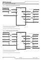
4.4.1 Analog Speed Signal with Yaskawa SGDV ...................................................... 4-4
4.4.2 Step/Dir Signal with Yaskawa SGDV ............................................................... 4-4
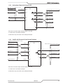
4.4.3 Analog Speed Signal with Panasonic A5 ......................................................... 4-5
4.4.4 Step/Dir with Panasonic A5 w/o Encoder Feedback ........................................ 4-5
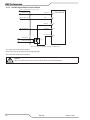
4.4.5 Step/Dir Signal without Encoder Feedback ..................................................... 4-6
SECTION 5: INPUT POWER ............................................................................... 5-1
5.1 Power Supply ................................................................................................. 5-1
5.2 Power Connector ............................................................................................ 5-1
5.2.1 Power Connector Pin Arrangement ................................................................. 5-1
SECTION 6: iHC ............................................................................................. 6-1
6.1 Lifter Specifications ........................................................................................ 6-1
6.1.2 Voltage Divider Dimensions ............................................................................ 6-2
6.2 Connector Locations ....................................................................................... 6-2
6.3 IO Example Connections ................................................................................. 6-3
6.4 J54 Lifter ........................................................................................................ 6-4
6.5 J55 Plasma ..................................................................................................... 6-5
6.6 J53 CNC .......................................................................................................... 6-6

TABLE OF CONTENTS
6.7 iHC Software ................................................................................................... 6-7
6.7.1 Pierce/Cut Sequence ....................................................................................... 6-7
6.7.2 IO Bits Tab ...................................................................................................... 6-8
6.7.3 Service Tab ..................................................................................................... 6-9
6.7.4 Installation Tab .............................................................................................. 6-10
6.7.5 Parameter Limits .......................................................................................... 6-11
SECTION 7: iCNC SETUP .................................................................................. 7-1
7.1 Initial Checks .................................................................................................. 7-1
7.2 Starting iCNC Setup ........................................................................................ 7-2
7.3 Motion, STEP/DIR ........................................................................................... 7-3
7.3.2 Drive and Encoder Polarities Step/Dir ............................................................. 7-4
7.3.3 Encoder Values Step/Dir ................................................................................. 7-5
7.3.4 Max Speed Adjustment Step/Dir ..................................................................... 7-6
7.3.5 Motion Parameters ......................................................................................... 7-6
7.4 Motion, Analog Speed ..................................................................................... 7-8
7.4.1 Drive Configuration Analog Speed .................................................................. 7-8
7.4.2 Drive and Encoder Polarities Analog Speed .................................................... 7-9
7.4.3 Encoder Values Analog Speed ...................................................................... 7-10
7.4.4 Drift Adjustment Analog Speed ..................................................................... 7-11
7.4.5 Max Speed Adjustment Analog Speed .......................................................... 7-11
7.4.6 Max Speed Test Analog Speed ...................................................................... 7-12
7.4.7 Min Speed Test Analog Speed ....................................................................... 7-12
7.4.8 Motion Parameters ....................................................................................... 7-13
7. I/O ................................................................................................................. 7-15
7.5.1 I/O General .................................................................................................... 7-15
7.5.2 I/O and Delay ................................................................................................ 7-17
7.5.2.1 I/O and Delay Plasma Cutting ....................................................................... 7-17
7.5.2.2 Advanced ...................................................................................................... 7-19
7.5.2.3 I/O and Delay Gas Cutting ............................................................................. 7-20
7.5.2.4 Custom ......................................................................................................... 7-21
7.5.2.5 Advanced ...................................................................................................... 7-22
7.5.2.6 I/O and Delay Line Marking ........................................................................... 7-22
7.5.3 Custom ......................................................................................................... 7-23
7.5.4 Advanced ...................................................................................................... 7-24
7.5.5 I/O Point Marking .......................................................................................... 7-25
7.5.6 I/O Outbit Names .......................................................................................... 7-26
7.5.7 I/O Inbit Names ............................................................................................. 7-26
7.6 Cutting Table Data ......................................................................................... 7-27
7.6.1 Homing / Limits ............................................................................................ 7-27
7.6.2 Down Draft ................................................................................................... 7-31
7.7 Others ........................................................................................................... 7-32
7.7.1 General ......................................................................................................... 7-32
7.7.2 THC/Plasma Settings ................................................................................... 7-33
7.7.3 Teach In ....................................................................................................... 7-34
7.7.4 Get Serial Number ........................................................................................ 7-34
7.7.5 Diagnostic Information ................................................................................. 7-34
7.7.6 Advanced Diagnostics ................................................................................... 7-34
7.7.7 Update Software ........................................................................................... 7-34
7.8 Backups ........................................................................................................ 7-34
7.8.1 Backup Machine Settings .............................................................................. 7-34
7.8.2 Restore Machine Settings ............................................................................. 7-35

TABLE OF CONTENTS
7.8.3 Restore Machine Settings from Backwall Backup USB ................................. 7-35
7.8.4 Create a System Image ................................................................................. 7-37
7.8.5 Restore a System Image ............................................................................... 7-38
7.9 Rotating Axis ................................................................................................ 7-38
7.9.1 Tangential Rotation ....................................................................................... 7-38
7.10 Hard Drive Lock ............................................................................................ 7-38
7.10.1 Change Status ............................................................................................... 7-38
8. Tool Offsets ................................................................................................... 7-39
8.1 Measuring the offset using a plasma power supply ...................................... 7-39
8.2 Setting the tool offset values ........................................................................ 7-40
SECTION 8: MAINTENANCE AND TROUBLESHOOTING ............................................... 8-1
8.1 Maintenance ................................................................................................... 8-1
8.2 Troubleshooting .............................................................................................. 8-1
8.2.1 Using Machine Info Screen for Troubleshooting ............................................. 8-1
8.2.1.1 Position and Speed Info .................................................................................. 8-1
8.2.1.2 Outbits Tab ...................................................................................................... 8-2
8.2.1.3 Inbits Tab ........................................................................................................ 8-3
8.2.1.4 Diagnostic Tools Tab ....................................................................................... 8-3
8.2.2 Boot and Power Issues ................................................................................... 8-4
8.2.3 Piercing and Cutting Issues ............................................................................ 8-4
8.2.4 Motion Issues ................................................................................................. 8-5
8.2.5 IO Issues/ Error Messages .............................................................................. 8-5
8.2.6 UI Errors ......................................................................................................... 8-6
8.2.7 Cut Quality ...................................................................................................... 8-6
8.3 Replacement Parts .......................................................................................... 8-7
APPENDIX A ................................................................................................. A-1
A.1 Bios settings ................................................................................................... A-1
A.2 Setting up SDSK Series Motors ...................................................................... A-2
A.2.1 Connecting to the Servo Motor ....................................................................... A-2
A.2.2 Autotune ......................................................................................................... A-4
A.2.3 Settings .......................................................................................................... A-7
A.2.4 Changing Motor Rotation Direction ................................................................ A-8
A.2.5 Final Settings .................................................................................................. A-8
APPENDIX B ................................................................................................. B-1
B.1 Servo Adapter Card (optional) ........................................................................ B-1
B1.1 Dimensions ..................................................................................................... B-1
B.1.2 Output Connectors .......................................................................................... B-2
B.1.3 Encoder Connectors ....................................................................................... B-3
B.1.4 Servo Connectors ........................................................................................... B-3
B.1.5 Input Connectors ............................................................................................ B-4
B.1.6 Teknic Connectors .......................................................................................... B-5
B.1.7 E-Stop Connectors .......................................................................................... B-6
B.1.8 Servo Adapter Card Connection Example........................................................ B-7
B.1.9 Servo Adapter Card Alternative Connections .................................................. B-8
B.2 Motors and Gearboxes .................................................................................... B-9
B.2.1 Teknic Nema23 ............................................................................................... B-9
B.2.2 Neugart PLPE 70 ............................................................................................ B-9
B.2.3 Teknic Nema34 ............................................................................................. B-10
B.2.4 Neugart PLPE 90 .......................................................................................... B-10
B.2.5 Lifter Motor ................................................................................................... B-11

TABLE OF CONTENTS
B.2.6 75VDC Power Suply Dimensions .................................................................. B-12
B.3 Thermal Dynamics A-Series Automation PCB ............................................... B-13
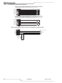
B.4 Cable Drawings ............................................................................................. B-14
B.4.1 Yaskawa Speed Loop Example ...................................................................... B-14
B.4.2 Panasonic A5 Speed Loop Example .............................................................. B-15
B.4.3 Panasonic A5 STEP/DIR Example ................................................................. B-16
B.4.4 Lifter Cable ................................................................................................... B-17
B.4.5 Collision Sensor Cable .................................................................................. B-18
B.4.6 Plasma and VDC Adapter Cable .................................................................... B-19
B.4.7 A-series Plasma Adapter Cable ..................................................................... B-20
B.4.8 Auto-Cut 200 XT Plasma Adapter Cable ........................................................ B-21
B.4.9 Ultra-Cut XT & Auto-Cut 300 XT Plasma Adapter Cable ................................ B-22
B.4.10 Ultra-Cut XT Communication Cable .............................................................. B-23
B.4.11 Ultra-Cut & Auto-Cut blue units (Sanrex) Plasma Adapter Cable .................. B-24
B.4.12 Connecting iHC to Panasonic A5 .................................................................. B-25
B.4.13 Y2 Alignment Cable For Teknic Motor ........................................................... B-26
STATEMENT OF WARRANTY

iCNC Performance
Manual 0-5401 SAFETY INSTRUCTIONS 1-1
SECTION 1: SAFETY
1.01 Safety Precautions - ENGLISH
WARNING: These Safety Precautions are for your protection. They summarize precautionary informa-
tion from the references listed in Additional Safety Information section. Before performing any instal-
lation or operating procedures, be sure to read and follow the safety precautions listed below as well
as all other manuals, material safety data sheets, labels, etc. Failure to observe Safety Precautions can result
in injury or death.
PROTECT YOURSELF AND OTHERS -- Some welding, cutting, and gouging processes are noisy
and require ear protection. The arc, like the sun, emits ultraviolet (UV) and other radiation and
can injure skin and eyes. Hot metal can cause burns. Training in the proper use of the pro-
cesses and equipment is essential to prevent accidents. Therefore:
1. Always wear safety glasses with side shields in any work area, even if welding helmets, face shields,
and goggles are also required.
2. Use a face shield fitted with the correct filter and cover plates to protect your eyes, face, neck, and
ears from sparks and rays of the arc when operating or observing operations. Warn bystanders not
to watch the arc and not to expose themselves to the rays of the electric-arc or hot metal.
3. Wear flameproof gauntlet type gloves, heavy long-sleeve shirt, cuffless trousers, high-topped shoes,
and a welding helmet or cap for hair protection, to protect against arc rays and hot sparks or hot metal.
A flameproof apron may also be desirable as protection against radiated heat and sparks.
4. Hot sparks or metal can lodge in rolled up sleeves, trouser cuffs, or pockets. Sleeves and collars
should be kept buttoned, and open pockets eliminated from the front of clothing.
5. Protect other personnel from arc rays and hot sparks with a suitable non-flammable partition or curtains.
6. Use goggles over safety glasses when chipping slag or grinding. Chipped slag may be hot and can
fly far. Bystanders should also wear goggles over safety glasses.
FIRES AND EXPLOSIONS -- Heat from flames and arcs can start fires. Hot slag or sparks can also
cause fires and explosions. Therefore:
1. Remove all combustible materials well away from the work area or cover the materials with a protective
non-flammable covering. Combustible materials include wood, cloth, sawdust, liquid and gas fuels,
solvents, paints and coatings, paper, etc.
2. Hot sparks or hot metal can fall through cracks or crevices in floors or wall openings and cause a
hidden smoldering fire or fires on the floor below. Make certain that such openings are protected
from hot sparks and metal.“
3. Do not weld, cut or perform other hot work until the work piece has been completely cleaned so that
there are no substances on the work piece which might produce flammable or toxic vapors. Do not
do hot work on closed containers. They may explode.
4. Have fire extinguishing equipment handy for instant use, such as a garden hose, water pail, sand
bucket, or portable fire extinguisher. Be sure you are trained in its use.
5. Do not use equipment beyond its ratings. For example, overloaded welding cable can overheat and
create a fire hazard.
6. After completing operations, inspect the work area to make certain there are no hot sparks or hot
metal which could cause a later fire. Use fire watchers when necessary.
7. For additional information, refer to NFPA Standard 51B, “Fire Prevention in Use of Cutting and Weld-
ing Processes”, available from the National Fire Protection Association, Battery march Park, Quincy,
MA 02269.

iCNC Performance
1-2 SAFETY INSTRUCTIONS Manual 0-5401
ELECTRICAL SHOCK -- Contact with live electrical parts and ground can cause severe injury or death.
DO NOT use AC welding current in damp areas, if movement is confined, or if there is danger of
falling.
1. Be sure the power source frame (chassis) is connected to the ground system of the input power.
2. Connect the work piece to a good electrical ground.
3. Connect the work cable to the work piece. A poor or missing connection can expose you or others
to a fatal shock.
4. Use well-maintained equipment. Replace worn or damaged cables.
5. Keep everything dry, including clothing, work area, cables, torch/electrode holder, and power source.
6. Make sure that all parts of your body are insulated from work and from ground.
7. Do not stand directly on metal or the earth while working in tight quarters or a damp area; stand on
dry boards or an insulating platform and wear rubber-soled shoes.
8. Put on dry, hole-free gloves before turning on the power.
9. Turn off the power before removing your gloves.
10. Refer to ANSI/ASC Standard Z49.1 (listed on next page) for specific grounding recommendations. Do
not mistake the work lead for a ground cable.
ELECTRIC AND MAGNETIC FIELDS — May be dangerous. Electric current flowing through any
conductor causes localized Electric and Magnetic Fields (EMF ). Welding and cutting current creates
EMF around welding cables and welding machines. Therefore:
1. Welders having pacemakers should consult their physician before welding. EMF may interfere with
some pacemakers.
2. Exposure to EMF may have other health effects which are unknown.
3. Welders should use the following procedures to minimize exposure to EMF:
A. Route the electrode and work cables together. Secure them with tape when possible.
B. Never coil the torch or work cable around your body.
C. Do not place your body between the torch and work cables. Route cables on the same side of your
body.
D. Connect the work cable to the work piece as close as possible to the area being welded.
E. Keep welding power source and cables as far away from your body as possible.
FUMES AND GASES -- Fumes and gases, can cause discomfort or harm, particularly in confined
spaces. Do not breathe fumes and gases. Shielding gases can cause asphyxiation.
Therefore:
1. Always provide adequate ventilation in the work area by natural or mechanical means. Do not weld,
cut, or gouge on materials such as galvanized steel, stainless steel, copper, zinc, lead, beryllium, or
cadmium unless positive mechanical ventilation is provided. Do not breathe fumes from these materials.
2. Do not operate near degreasing and spraying operations. The heat or arc rays can react with chlorinated
hydrocarbon vapors to form phosgene, a highly toxic gas, and other irritant gases.
3. If you develop momentary eye, nose, or throat irritation while operating, this is an indication that
ventilation is not adequate. Stop work and take necessary steps to improve ventilation in the work
area. Do not continue to operate if physical discomfort persists.
4. Refer to ANSI/ASC Standard Z49.1 (see listing below) for specific ventilation recommendations.
5. WARNING: This product contains chemicals, including lead, known to the State of California to cause
birth defects and other reproductive harm. Wash hands after handling.

iCNC Performance
Manual 0-5401 SAFETY INSTRUCTIONS 1-3
CYLINDER HANDLING -- Cylinders, if mishandled, can rupture and violently release gas. Sudden
rupture of cylinder, valve, or relief device can injure or kill. Therefore:
1. Use the proper gas for the process and use the proper pressure reducing regulator designed to operate
from the compressed gas cylinder. Do not use adaptors. Maintain hoses and fittings in good condition.
Follow manufacturer’s operating instructions for mounting regulator to a compressed gas cylinder.
2. Always secure cylinders in an upright position by chain or strap to suitable hand trucks, undercar-
riages, benches, walls, post, or racks. Never secure cylinders to work tables or fixtures where they
may become part of an electrical circuit.
3. When not in use, keep cylinder valves closed. Have valve protection cap in place if regulator is not con-
nected. Secure and move cylinders by using suitable hand trucks. Avoid rough handling of cylinders.
4. Locate cylinders away from heat, sparks, and flames. Never strike an arc on a cylinder.
5. For additional information, refer to CGA Standard P-1, “Precautions for Safe Handling of Compressed
Gases in Cylinders”, which is available from Compressed Gas Association, 1235 Jefferson Davis
Highway, Arlington, VA 22202.
EQUIPMENT MAINTENANCE -- Faulty or improperly maintained equipment can cause injury or death.
Therefore:
1. Always have qualified personnel perform the installation, troubleshooting, and maintenance work. Do
not perform any electrical work unless you are qualified to perform such work.
2. Before performing any maintenance work inside a power source, disconnect the power source from
the incoming electrical power.
3. Maintain cables, grounding wire, connections, power cord, and power supply in safe working order.
Do not operate any equipment in faulty condition.
4. Do not abuse any equipment or accessories. Keep equipment away from heat sources such as furnaces,
wet conditions such as water puddles, oil or grease, corrosive atmospheres and inclement weather.
5. Keep all safety devices and cabinet covers in position and in good repair.
6. Use equipment only for its intended purpose. Do not modify it in any manner.
ADDITIONAL SAFETY INFORMATION -- For more information on safe practices for electric arc weld-
ing and cutting equipment, ask your supplier for a copy of “Precautions and Safe Practices for Arc
Welding, Cutting and Gouging”, Form 52-529.
The following publications, which are available from the American Welding Society, 550 N.W. LeJuene Road,
Miami, FL 33126, are recommended to you:
1. ANSI/ASC Z49.1 - “Safety in Welding and Cutting”.
2. AWS C5.1 - “Recommended Practices for Plasma Arc Welding”.
3. AWS C5.2 - “Recommended Practices for Plasma Arc Cutting”.
4. AWS C5.3 - “Recommended Practices for Air Carbon Arc Gouging and Cutting”.
5. AWS C5.5 - “Recommended Practices for Gas Tungsten Arc Welding“.
6. AWS C5.6 - “Recommended Practices for Gas Metal Arc Welding”.
7. AWS SP - “Safe Practices” - Reprint, Welding Handbook.
8. ANSI/AWS F4.1, “Recommended Safe Practices for Welding and Cutting of Containers That Have Held
Hazardous Substances.”
9. CSA Standard - W117.2 = Safety in Welding, Cutting and Allied Processes.

iCNC Performance
1-4 SAFETY INSTRUCTIONS Manual 0-5401
Meaning of symbols - As used throughout this manual: Means Attention! Be Alert! Your safety is involved.
DANGER
Means immediate hazards which, if not avoided, will result in immediate, serious
personal injury or loss of life.
CAUTION
Means potential hazards which could result in personal injury or loss of life.
WARNING
Means hazards which could result in minor personal injury.
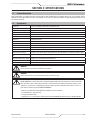
Enclosure Class
The IP code indicates the enclosure class, i.e. the degree of protection against penetration by solid objects or
water. Protection is provided against touch with a finger, penetration of solid objects greater than 12mm and
against spraying water up to 60 degrees from vertical. Equipment marked IP21S may be stored, but is not
intended to be used outside during precipitation unless sheltered.
CAUTION
This product is solely intended for plasma cutting. Any other use may result in per-
sonal injury and / or equipment damage.
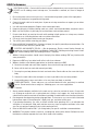
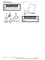
CAUTION
If equipment is placed on a surface that slopes more
than 15°, toppling over may occur. Personal injury and
/ or signicant damage to equipment is possible.
15
°
Art# A-12726
Art# A-12736
CAUTION
To avoid personal injury and/or equipment damage,
lift using method and attachment points shown here.

iCNC Performance
Manual 0-5401 SAFETY INSTRUCTIONS 1-5
This Page Intentionally Blank

iCNC Performance
1-6 SAFETY INSTRUCTIONS Manual 0-5401
1.02 Précautions de sécurité - FRENCH CANADIAN
AVERTISSEMENT : Ces règles de sécurité ont pour but d’assurer votre protection. Ils récapitulent les
informations de précaution provenant des références dans la section des Informations de sécurité
supplémentaires. Avant de procéder à l’installation ou d’utiliser l’unité, assurez-vous de lire et de
suivre les précautions de sécurité ci-dessous, dans les manuels, les fiches d’information sur la sécurité du
matériel et sur les étiquettes, etc. Tout défaut d’observer ces précautions de sécurité peut entraîner des bles-
sures graves ou mortelles.
PROTÉGEZ-VOUS -- Les processus de soudage, de coupage et de gougeage produisent un
niveau de bruit élevé et exige l’emploi d’une protection auditive. L’arc, tout comme le soleil,
émet des rayons ultraviolets en plus d’autre rayons qui peuvent causer des blessures à la peau
et les yeux. Le métal incandescent peut causer des brûlures. Une formation reliée à l’usage des processus et
de l’équipement est essentielle pour prévenir les accidents. Par conséquent:
1. Portez des lunettes protectrices munies d’écrans latéraux lorsque vous êtes dans l’aire de travail, même
si vous devez porter un casque de soudeur, un écran facial ou des lunettes étanches.
2. Portez un écran facial muni de verres filtrants et de plaques protectrices appropriées afin de protéger
vos yeux, votre visage, votre cou et vos oreilles des étincelles et des rayons de l’arc lors d’une opé-
ration ou lorsque vous observez une opération. Avertissez les personnes se trouvant à proximité de
ne pas regarder l’arc et de ne pas s’exposer aux rayons de l’arc électrique ou le métal incandescent.
3. Portez des gants ignifugiés à crispin, une chemise épaisse à manches longues, des pantalons sans
rebord et des chaussures montantes afin de vous protéger des rayons de l’arc, des étincelles et du
métal incandescent, en plus d’un casque de soudeur ou casquette pour protéger vos cheveux. Il est
également recommandé de porter un tablier ininflammable afin de vous protéger des étincelles et de
la chaleur par rayonnement.
4. Les étincelles et les projections de métal incandescent risquent de se loger dans les manches retrous-
sées, les rebords de pantalons ou les poches. Il est recommandé de garder boutonnés le col et les
manches et de porter des vêtements sans poches en avant.
5. Protégez toute personne se trouvant à proximité des étincelles et des rayons de l’arc à l’aide d’un
rideau ou d’une cloison ininflammable.
6. Portez des lunettes étanches par dessus vos lunettes de sécurité lors des opérations d’écaillage ou de
meulage du laitier. Les écailles de laitier incandescent peuvent être projetées à des distances consi-
dérables. Les personnes se trouvant à proximité doivent également porter des lunettes étanches par
dessus leur lunettes de sécurité.
INCENDIES ET EXPLOSIONS -- La chaleur provenant des flammes ou de l’arc peut provoquer un
incendie. Le laitier incandescent ou les étincelles peuvent également provoquer un incendie ou une
explosion. Par conséquent :
1. Éloignez suffisamment tous les matériaux combustibles de l’aire de travail et recouvrez les matériaux
avec un revêtement protecteur ininflammable. Les matériaux combustibles incluent le bois, les vête-
ments, la sciure, le gaz et les liquides combustibles, les solvants, les peintures et les revêtements, le
papier, etc.
2. Les étincelles et les projections de métal incandescent peuvent tomber dans les fissures dans les
planchers ou dans les ouvertures des murs et déclencher un incendie couvant à l’étage inférieur
Assurez-vous que ces ouvertures sont bien protégées des étincelles et du métal incandescent.
3. N’exécutez pas de soudure, de coupe ou autre travail à chaud avant d’avoir complètement nettoyé la
surface de la pièce à traiter de façon à ce qu’il n’ait aucune substance présente qui pourrait produire
des vapeurs inflammables ou toxiques. N’exécutez pas de travail à chaud sur des contenants fermés
car ces derniers pourraient exploser.
4. Assurez-vous qu’un équipement d’extinction d’incendie est disponible et prêt à servir, tel qu’un tuyau
d’arrosage, un seau d’eau, un seau de sable ou un extincteur portatif. Assurez-vous d’être bien instruit
par rapport à l’usage de cet équipement.

iCNC Performance
Manual 0-5401 SAFETY INSTRUCTIONS 1-7
5. Assurez-vous de ne pas excéder la capacité de l’équipement. Par exemple, un câble de soudage
surchargé peut surchauffer et provoquer un incendie.
6. Une fois les opérations terminées, inspectez l’aire de travail pour assurer qu’aucune étincelle ou
projection de métal incandescent ne risque de provoquer un incendie ultérieurement. Employez des
guetteurs d’incendie au besoin.
7. Pour obtenir des informations supplémentaires, consultez le NFPA Standard 51B, “Fire Prevention
in Use of Cutting and Welding Processes”, disponible au National Fire Protection Association, Batte-
rymarch Park, Quincy, MA 02269.
CHOC ÉLECTRI QUE -- Le contact avec des pièces électriques ou les pièces de mise à la terre sous
tension peut causer des blessures graves ou mortelles. NE PAS utiliser un courant de soudage c.a.
dans un endroit humide, en espace restreint ou si un danger de chute se pose.
1. Assurez-vous que le châssis de la source d’alimentation est branché au système de mise à la terre
de l’alimentation d’entrée.
2. Branchez la pièce à traiter à une bonne mise de terre électrique.
3. Branchez le câble de masse à la pièce à traiter et assurez une bonne connexion afin d’éviter le risque
de choc électrique mortel.
4. Utilisez toujours un équipement correctement entretenu. Remplacez les câbles usés ou endommagés.
5. Veillez à garder votre environnement sec, incluant les vêtements, l’aire de travail, les câbles, le por-
teélectrode/torche et la source d’alimentation.
6. Assurez-vous que tout votre corps est bien isolé de la pièce à traiter et des pièces de la mise à la terre.
7. Si vous devez effectuer votre travail dans un espace restreint ou humide, ne tenez vous pas directement
sur le métal ou sur la terre; tenez-vous sur des planches sèches ou une plate-forme isolée et portez
des chaussures à semelles de caoutchouc.
8. Avant de mettre l’équipement sous tension, isolez vos mains avec des gants secs et sans trous.
9. Mettez l’équipement hors tension avant d’enlever vos gants.
10. Consultez ANSI/ASC Standard Z49.1 (listé à la page suivante) pour des recommandations spécifiques
concernant les procédures de mise à la terre. Ne pas confondre le câble de masse avec le câble de
mise à la terre.
CHAMPS ÉLECTRIQUES ET MAGNÉTIQUES — comportent un risque de danger. Le courant élec-
trique qui passe dans n’importe quel conducteur produit des champs électriques et magnétiques
localisés. Le soudage et le courant de coupage créent des champs électriques et magnétiques
autour des câbles de soudage et l’équipement. Par conséquent :
1. Un soudeur ayant un stimulateur cardiaque doit consulter son médecin avant d’entreprendre une
opération de soudage. Les champs électriques et magnétiques peuvent causer des ennuis pour cer-
tains stimulateurs cardiaques.
2. L’exposition à des champs électriques et magnétiques peut avoir des effets néfastes inconnus pour
la santé.
3. Les soudeurs doivent suivre les procédures suivantes pour minimiser l’exposition aux champs élec-
triques et magnétiques :
A. Acheminez l’électrode et les câbles de masse ensemble. Fixez-les à l’aide d’une bande adhésive
lorsque possible.
B. Ne jamais enrouler la torche ou le câble de masse autour de votre corps.
C. Ne jamais vous placer entre la torche et les câbles de masse. Acheminez tous les câbles sur le
même côté de votre corps.
D. Branchez le câble de masse à la pièce à traiter le plus près possible de la section à souder.
E. Veillez à garder la source d’alimentation pour le soudage et les câbles à une distance appropriée
de votre corps.

iCNC Performance
1-8 SAFETY INSTRUCTIONS Manual 0-5401
LES VAPEURS ET LES GAZ -- peuvent causer un malaise ou des dommages corporels, plus par-
ticulièrement dans les espaces restreints. Ne respirez pas les vapeurs et les gaz. Le gaz de protec-
tion risque de causer l’asphyxie.
Par conséquent :
1. Assurez en permanence une ventilation adéquate dans l’aire de travail en maintenant une ventilation
naturelle ou à l’aide de moyens mécanique. N’effectuez jamais de travaux de soudage, de coupage
ou de gougeage sur des matériaux tels que l’acier galvanisé, l’acier inoxydable, le cuivre, le zinc, le
plomb, le berylliym ou le cadmium en l’absence de moyens mécaniques de ventilation efficaces. Ne
respirez pas les vapeurs de ces matériaux.
2. N’effectuez jamais de travaux à proximité d’une opération de dégraissage ou de pulvérisation. Lors-
que la chaleur ou le rayonnement de l’arc entre en contact avec les vapeurs d’hydrocarbure chloré,
ceci peut déclencher la formation de phosgène ou d’autres gaz irritants, tous extrêmement toxiques.
3. Une irritation momentanée des yeux, du nez ou de la gorge au cours d’une opération indique que
la ventilation n’est pas adéquate. Cessez votre travail afin de prendre les mesures nécessaires pour
améliorer la ventilation dans l’aire de travail. Ne poursuivez pas l’opération si le malaise persiste.
4. Consultez ANSI/ASC Standard Z49.1 (à la page suivante) pour des recommandations spécifiques
concernant la ventilation.
5. AVERTISSEMENT : Ce produitcontient des produits chimiques, notamment du plomb, reconnu par
l’Étatde la Californie pour causerdes malformations congénitaleset d’autresdommages touchant le
système reproductif.
Se laver les mainsaprès manipulation.
MANIPULATION DES CYLINDRES -- La manipulation d’un cylindre, sans observer les précautions
nécessaires, peut produire des fissures et un échappement dangereux des gaz. Une brisure sou-
daine du cylindre, de la soupape ou du dispositif de surpression peut causer des blessures graves
ou mortelles. Par conséquent :
1. Utilisez toujours le gaz prévu pour une opération et le détendeur approprié conçu pour utilisation sur
les cylindres de gaz comprimé. N’utilisez jamais d’adaptateur. Maintenez en bon état les tuyaux et
les raccords. Observez les instructions d’opération du fabricant pour assembler le détendeur sur un
cylindre de gaz comprimé.
2. Fixez les cylindres dans une position verticale, à l’aide d’une chaîne ou une sangle, sur un chariot
manuel, un châssis de roulement, un banc, un mur, une colonne ou un support convenable. Ne fixez
jamais un cylindre à un poste de travail ou toute autre dispositif faisant partie d’un circuit électrique.
3. Lorsque les cylindres ne servent pas, gardez les soupapes fermées. Si le détendeur n’est pas branché,
assurez-vous que le bouchon de protection de la soupape est bien en place. Fixez et déplacez les
cylindres à l’aide d’un chariot manuel approprié. Toujours manipuler les cylindres avec soin.
4. Placez les cylindres à une distance appropriée de toute source de chaleur, des étincelles et des flam-
mes. Ne jamais amorcer l’arc sur un cylindre.
5. Pour de l’information supplémentaire, consultez CGA Standard P-1, “Precautions for Safe Handling of
Compressed Gases in Cylinders”, mis à votre disposition par le Compressed Gas Association, 1235
Jefferson Davis Highway, Arlington, VA 22202.
ENTRETIEN DE L’ÉQUIPEMENT -- Un équipement entretenu de façon défectueuse ou inadéquate peut
causer des blessures graves ou mortelles. Par conséquent :
1. Efforcez-vous de toujours confier les tâches d’installation, de dépannage et d’entretien à un personnel
qualifié. N’effectuez aucune réparation électrique à moins d’être qualifié à cet effet.
2. Avant de procéder à une tâche d’entretien à l’intérieur de la source d’alimentation, débranchez l’ali-
mentation électrique.
3. Maintenez les câbles, les fils de mise à la terre, les branchements, le cordon d’alimentation et la source
d’alimentation en bon état. N’utilisez jamais un équipement s’il présente une défectuosité quelconque.
La page charge ...
La page charge ...
La page charge ...
La page charge ...
La page charge ...
La page charge ...
La page charge ...
La page charge ...
La page charge ...
La page charge ...
La page charge ...
La page charge ...
La page charge ...
La page charge ...
La page charge ...
La page charge ...
La page charge ...
La page charge ...
La page charge ...
La page charge ...
La page charge ...
La page charge ...
La page charge ...
La page charge ...
La page charge ...
La page charge ...
La page charge ...
La page charge ...
La page charge ...
La page charge ...
La page charge ...
La page charge ...
La page charge ...
La page charge ...
La page charge ...
La page charge ...
La page charge ...
La page charge ...
La page charge ...
La page charge ...
La page charge ...
La page charge ...
La page charge ...
La page charge ...
La page charge ...
La page charge ...
La page charge ...
La page charge ...
La page charge ...
La page charge ...
La page charge ...
La page charge ...
La page charge ...
La page charge ...
La page charge ...
La page charge ...
La page charge ...
La page charge ...
La page charge ...
La page charge ...
La page charge ...
La page charge ...
La page charge ...
La page charge ...
La page charge ...
La page charge ...
La page charge ...
La page charge ...
La page charge ...
La page charge ...
La page charge ...
La page charge ...
La page charge ...
La page charge ...
La page charge ...
La page charge ...
La page charge ...
La page charge ...
La page charge ...
La page charge ...
La page charge ...
La page charge ...
La page charge ...
La page charge ...
La page charge ...
La page charge ...
La page charge ...
La page charge ...
La page charge ...
La page charge ...
La page charge ...
La page charge ...
La page charge ...
La page charge ...
La page charge ...
La page charge ...
La page charge ...
La page charge ...
La page charge ...
La page charge ...
La page charge ...
La page charge ...
La page charge ...
La page charge ...
La page charge ...
La page charge ...
La page charge ...
La page charge ...
La page charge ...
La page charge ...
La page charge ...
La page charge ...
La page charge ...
La page charge ...
La page charge ...
La page charge ...
La page charge ...
La page charge ...
-
 1
1
-
 2
2
-
 3
3
-
 4
4
-
 5
5
-
 6
6
-
 7
7
-
 8
8
-
 9
9
-
 10
10
-
 11
11
-
 12
12
-
 13
13
-
 14
14
-
 15
15
-
 16
16
-
 17
17
-
 18
18
-
 19
19
-
 20
20
-
 21
21
-
 22
22
-
 23
23
-
 24
24
-
 25
25
-
 26
26
-
 27
27
-
 28
28
-
 29
29
-
 30
30
-
 31
31
-
 32
32
-
 33
33
-
 34
34
-
 35
35
-
 36
36
-
 37
37
-
 38
38
-
 39
39
-
 40
40
-
 41
41
-
 42
42
-
 43
43
-
 44
44
-
 45
45
-
 46
46
-
 47
47
-
 48
48
-
 49
49
-
 50
50
-
 51
51
-
 52
52
-
 53
53
-
 54
54
-
 55
55
-
 56
56
-
 57
57
-
 58
58
-
 59
59
-
 60
60
-
 61
61
-
 62
62
-
 63
63
-
 64
64
-
 65
65
-
 66
66
-
 67
67
-
 68
68
-
 69
69
-
 70
70
-
 71
71
-
 72
72
-
 73
73
-
 74
74
-
 75
75
-
 76
76
-
 77
77
-
 78
78
-
 79
79
-
 80
80
-
 81
81
-
 82
82
-
 83
83
-
 84
84
-
 85
85
-
 86
86
-
 87
87
-
 88
88
-
 89
89
-
 90
90
-
 91
91
-
 92
92
-
 93
93
-
 94
94
-
 95
95
-
 96
96
-
 97
97
-
 98
98
-
 99
99
-
 100
100
-
 101
101
-
 102
102
-
 103
103
-
 104
104
-
 105
105
-
 106
106
-
 107
107
-
 108
108
-
 109
109
-
 110
110
-
 111
111
-
 112
112
-
 113
113
-
 114
114
-
 115
115
-
 116
116
-
 117
117
-
 118
118
-
 119
119
-
 120
120
-
 121
121
-
 122
122
-
 123
123
-
 124
124
-
 125
125
-
 126
126
-
 127
127
-
 128
128
-
 129
129
-
 130
130
-
 131
131
-
 132
132
-
 133
133
-
 134
134
-
 135
135
-
 136
136
-
 137
137
-
 138
138


ESAB iCNC Performance CNC Controller Manuel utilisateur
- Catégorie
- Système de soudage
- Taper
- Manuel utilisateur
dans d''autres langues
Documents connexes
-
Thermal Dynamics iCNC Performance CNC Controller Le manuel du propriétaire
-
-
ESAB M3® Plasma G2 Plasma System - ICH Manuel utilisateur
-
-
-
Autres documents
-
 Thermal Dynamics iHC XT Mode d'emploi
-
GYS CNC-2 kit - Digital - Mechanized plasma cutting Le manuel du propriétaire
-
 Toparc KIT CNC-2 / CNC-3 Benchtop Standard Machine Kit Manuel utilisateur
-
DataVideo PD-6 Manuel utilisateur
-
Mitsubishi Electric SSCNETⅢ/H Compatible Optical Hub Unit Manuel utilisateur
-
Dwyer Series MSP Manuel utilisateur
-
Miller SUBARC INTERFACE ANALOG CE Le manuel du propriétaire
-
Miller MAXSTAR 800 Le manuel du propriétaire
-
Miller MH170718L Le manuel du propriétaire
-
Miller SUBARC SYSTEM DIGITAL ACCESSORIES CE Le manuel du propriétaire

