
BLODGETT OVEN COMPANY
www.blodgett.com
44 Lakeside Avenue, Burlington, Vermont 05401 USA Telephone (802) 658Ć6600 Fax: (802)864Ć0183
PN 52424 Rev H (6/11)
E 2011- G.S. Blodgett Corporation
HVĆ100E and HVĆ100G
INSTALLATION - OPERATION - MAINTENANCE
HVĆ100E et HVĆ100G
MANUEL D'INSTALLATION - FONCTIONNEMENT - ENTRETIEN

THE REPUTATION YOU CAN COUNT ON
UNE RÉPUTATION SUR LAQUELLE VOUS POUVEZ COMPTER
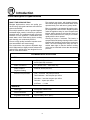
For over a century and a half, The Blodgett Oven Company has been building
ovens and nothing but ovens. We've set the industry's quality standard for all
kinds of ovens for every foodservice operation regardless of size, application
or budget. In fact, no one offers more models, sizes, and oven applications
than Blodgett; gas and electric, fullĆsize, halfĆsize, countertop and deck, conĆ
vection, Cook'n Hold, CombiĆOvens and the industry's highest quality Pizza
Oven line. For more information on the full line of Blodgett ovens contact your
Blodgett representative.
Cela fait maintenant dessus un siècle et demi que Blodgett se spécialise dans
la fabrication de fours. Nous avons établi les normes de qualité qui s'appliĆ
quent dans l'industrie à tous les types de fours utilisés dans les services aliĆ
mentaires, quel qu'en soit la taille, l'exploitation ou le budget. En fait, ni n'offre
plus de modèles, de tailles et d'applications de fours que Blodgett. À gaz et
électriques. De tailles différentes, sur plan de travail et superposables. Qu'il
s'agisse de fours à convection, des modèles Cook'n Hold et CombiĆOven, ou
de la gamme de fours à pizzas de la plus haute qualité offerte sur le marché.
Pour de plus amples informations sur la gamme complète de fours Blodgett,
veuillez contacter votre représentant Blodgett.

IMPORTANT
FOR YOUR SAFETY
Do not store or use gasoline or other flammable vapors or liquids in the vicinity
of this or any other appliance.
AVERTISSEMENT
Ne pas entreposer ni utiliser de l'essence ni d'autres vapeurs ou liquides inflamĆ
mables dans le voisinage de cet appariel, ni de tout autre appareil.
WARNING: IMPROPER INSTALLATION, ADJUSTMENT, ALTERATION, SERVICE OR
MAINTENANCE CAN CAUSE PROPERTY DAMAGE, INJURY OR DEATH. READ THE
INSTALLATION, OPERATING AND MAINTENANCE INSTRUCTIONS THOROUGHLY
BEFORE INSTALLING OR SERVICING THIS EQUIPMENT
AVERTISSEMENT: UNE INSTALLATION, UN AJUSTEMENT, UNE ALTÉRATION, UN
SERVICE OU UN ENTRETIEN NON CONFORME AUX NORMES PEUT CAUSER DES
DOMMAGES À LA PROPRIÉTE, DES BLESSURES OU LA MORT. LISEZ ATTENTIVEĆ
MENT LES DIRECTIVES D'INSTALLATION, D'OPÉRATION ET D'ENTRETIEN AVANT
DE FAIRE L'INSTALLATION OU L'ENTRETIEN DE CET ÉQUIPEMENT.
The information contained in this manual is important for the proper installation,
use, and maintenance of this oven. Adherence to these procedures and instrucĆ
tions will result in satisfactory baking results and long, trouble free service.
Please read this manual carefully and retain it for future reference.
Les informations données dans le présent manuel sont importantes pour installer,
utiliser et entretenir correctement ce four. Le respect de ces instructions et procéĆ
dures permettra d'obtenir de bons résultats de cuisson et une longue durée de serĆ
vice sans problèmes. Veuillez lire le présent manuel et le conserver pour pouvoir
vous y reporter à l'avenir.
Errors: Descriptive, typographic or pictorial errors are subject to correction. SpecificaĆ
tions are subject to change without notice.
Erreurs:Les erreurs de description, de typographie ou d'illustration font l'objet de
corrections. Les caractéristiques sont sujettes à modifications sans préavis.

Your Service Agency's Address:
Adresse de votre agence de service:
Model/Modèl:
Serial Number/Numéro de série:
Your appliance was installed by/
Installateur de votre four:
Your oven's installation was checked by/
Contrôleur de l'installation de votre four:

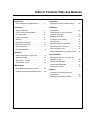
Table of Contents/Table des Matières
Introduction
Oven Description & Specifications 2. . . . . .
Installation
Agency Approvals 4. . . . . . . . . . . . . . . . . . . .
Oven Location and Ventilation 5. . . . . . . . . .
Leg Attachment 6. . . . . . . . . . . . . . . . . . . . . .
Caster Attachment 7. . . . . . . . . . . . . . . . . . . .
Stacking 8. . . . . . . . . . . . . . . . . . . . . . . . . . . . .
Plumbing Connections 9. . . . . . . . . . . . . . . .
Electrical Connections 10. . . . . . . . . . . . . . . .
Gas Connections 11. . . . . . . . . . . . . . . . . . . . .
Gas Hose Restraint 13. . . . . . . . . . . . . . . . . . .
Operation
Safety Information for Gas Units 14. . . . . . . .
Standard Control 15. . . . . . . . . . . . . . . . . . . . .
MenuSelectt Control 17. . . . . . . . . . . . . . . . .
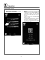
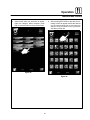
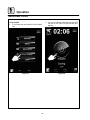
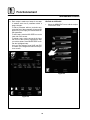
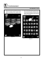
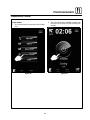
Touchscreen Control 23. . . . . . . . . . . . . . . . . .
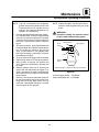
Maintenance
Spray Bottle Operating Procedure 33. . . . . .
Cleaning and Preventive Maintenance 34. . .
Introduction
Description du four et Spécifications 36. . . .
Installation
Certifications 38. . . . . . . . . . . . . . . . . . . . . . . . .
Emplacement du four et mise de
niveau et Ventilation 39. . . . . . . . . . . . . . . . . . .
Montage des pieds 40. . . . . . . . . . . . . . . . . . .
Accessoire des roulettes 41. . . . . . . . . . . . . .
Superposition 42. . . . . . . . . . . . . . . . . . . . . . . .
Raccordement de la plomberie 43. . . . . . . . .
Raccordement à l'électricité 44. . . . . . . . . . . .
Raccordement au gaz 45. . . . . . . . . . . . . . . . .
Câble d'immobilisation du tuyau à gaz 47. .
Fonctionnement
Renseignements sur la sécurité des
appareils au gaz 48. . . . . . . . . . . . . . . . . . . . . .
Commandes standard 49. . . . . . . . . . . . . . . .
Commande MenuSelectt 51. . . . . . . . . . . . .
Touchscreen Control 59. . . . . . . . . . . . . . . . . .
Entretien
Procédure de fonctionnement du
pulvérisateur 69. . . . . . . . . . . . . . . . . . . . . . . . .
Nettoyage et entretien préventif 70. . . . . . . .

Introduction
2
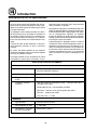
Oven Description & Specifications
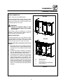
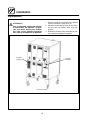
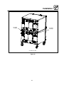
ABOUT THE HYDROVECTION
Blodgett Hydrovection ovens are quality proĆ
duced using highĆgrade stainless steel with first
class workmanship.
The multiple speed fan, which is guarded against
accidental finger contact, is driven by a quiet and
powerful motor. The condenser draws out excess
moisture from the appliance. Condensation and
waste water, which result during hydro cooking
and cleaning, are continuously drained.
The use of high quality insulation impedes excesĆ
sive heat radiation and saves energy.
The Hydrovection has optional adjustable legs
which adapt easily to slightly uneven surfaces and
optional floor stands which are designed for use
with all of the table models.
The practical oven doors, with viewing windows,
have a wide swing radius and handle which can be
operated easily, even with wet or greasy hands.
Ease of operation is guaranteed through the simĆ
ple arrangement of the controls. Graphic symbols
make the appliance easy for even inexperienced
kitchen staff to operate. A third function, the Cool
Down mode, allows the oven cavity to cool down
rapidly with the door opened.
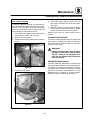
Cleaning is kept to a minimum. The interior is
sprayed with a selfĆacting cleaning solution which
interacts with humidity to easily remove crusts and
stains. The oven is designed for easy care and is
welded water tight so that the internal cooking
cavity may be rinsed with a hose after the cleaning
process.
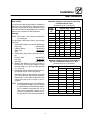
PLUMBING SPECIFICATIONS
WATER
Water Pressure 30 PSI (207 kPa) minimum
50 PSI (345 kPa) maximum
Water Connection 3/4" garden hose - Cold water only
Water Pressure
Regulator Setting
Preset to 30 PSI (207 kPa)
Minimum Requirements TDS - less than 100 parts per million
Total Hardness - 80Ć120 parts per million
Chlorides - less than 30 parts per million
Chlorine - 0 parts per million
pH Factor - 7.0Ć8.0
DRAINAGE
Drain Type Atmospheric Vented Drain
Drain Connection 1" NPT Male
Avg Water Drain Temp. Approximately 140_F (60_C)

Introduction
3
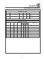
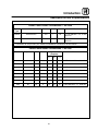
Oven Description & Specifications
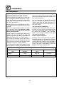
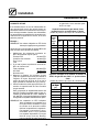
RATINGS - HVĆ100G
Gas Type Gas Input Voltage Phase Amps Motor
Natural 60,000 BTU/Hr 120 1 20 1/2 HP 208Ć240VAC, 3 phase,
50/60 Hz
Propane 60,000 BTU/Hr 120 1 20 1/2 HP 208Ć240VAC, 3 phase,
50/60 Hz
3/4" NPT connector for all U.S. and Canadian installations
RATINGS - HVĆ100E
Voltage Hz kW Phase
Max Load (amps)
Motor
L1 L2 L3
208 60 15 3 38 38 38 1/2 HP 208Ć240VAC, 50/60 Hz
240 60 15 3 36 34 34 1/2 HP 208Ć240VAC, 50/60 Hz
440 60 15 3 20 18 18 1/2 HP 208Ć240VAC, 50/60 Hz
480 60 15 3 18 17 17 1/2 HP 208Ć240VAC, 50/60 Hz
208 60 13 3 33 33 36 1/2 HP 208Ć240VAC, 50/60 Hz
240 60 13 3 31 29 29 1/2 HP 208Ć240VAC, 50/60 Hz
440 60 13 3 16 16 17 1/2 HP 208Ć240VAC, 50/60 Hz
480 60 13 3 15 15 16 1/2 HP 208Ć240VAC, 50/60 Hz

Installation
4
Agency Approvals
THE INSTALLATION INSTRUCTIONS CONĆ
TAINED HEREIN ARE FOR THE USE OF QUALIĆ
FIED INSTALLATION AND SERVICE PERSONNEL
ONLY. INSTALLATION OR SERVICE BY OTHER
THAN QUALIFIED PERSONNEL MAY RESULT IN
DAMAGE TO THE OVEN AND/OR INJURY TO
THE OPERATOR.
Qualified installation personnel are individuals, a
firm, a corporation, or a company which either in
person or through a representative are engaged
in, and are responsible for:
D The installation or replacement of gas piping.
The connection, installation, repair or servicing
of equipment.
D The installation of electrical wiring from the elecĆ
tric meter, main control box or service outlet to
the electric appliance.
Qualified installation personnel must be experiĆ
enced in such work, be familiar with all precauĆ
tions required and have complied with all requireĆ
ments of state or local authorities having
jurisdiction.
U.S. and Canadian Installations
Installation must conform with local codes, or in
the absence of local codes, with the National Fuel
Gas Code, NFPA54/ANSI Z223.1-Latest Edition,
the Natural Gas Installation Code CAN/CGAĆ
B149.1 or the Propane Installation Code, CAN/
CGAĆB149.2 as applicable.
Reference: National Electrical Code, ANSI/NFPA
70-Latest Edition and/or Canadian Electrical
Code CSA C22.1 as applicable.
This equipment is to be installed in compliance
with the Basic Plumbing Code of the Building OffiĆ
cials and Code Administrators International Inc.
(BOCA) and the Food Service Sanitation Manual of
the Food and Drug Administration (FDA).
Appliance is to be installed with backflow prevenĆ
tion in accordance with applicable federal, provĆ
ince and local codes.
General Export Installations
Installation must conform with Local and National
installation standards. Local installation codes and/
or requirements may vary. If you have any questions
regarding the proper installation and/or operation of
your appliance, please contact your local distributor.
If you do not have a local distributor, please call
Blodgett at 0011Ć802Ć658Ć6600.

Installation
5
Oven Location and Ventilation
OWNER'S RESPONSIBILITIES
Installation responsibilities prior to service
startup inspection
You are entitled to a free startĆup inspection serĆ
vice by our factory ASAP. Before a factory repreĆ
sentative arrives to perform a startup procedure,
the owner must already have satisfied the followĆ
ing requirements.
1. Oven(s) are uncrated, stacked (if applies) and
put in place.
NOTE: Please refer to Leg Attachment and
Stacking.
Maximum shelf loading - 60 lbs (27.3 Kg)
OVEN LOCATION
The well planned and proper placement of your
oven will result in long term operator convenience
and satisfactory performance.
Certain minimum clearances must be maintained
between the oven and any combustible or nonĆ
combustible construction. See the table below.
In addition, the following clearances are recomĆ
mended for servicing.
D Oven body sides - 12" (30cm)
D Oven body back - 12" (30cm)
Oven
Mdl
MINIMUM REQUIRED
CLEARANCES
Model
Right
Side
Left
Side
Back
HVĆ100E 0"
(0mm)
0"
(0mm)
6"
(152.4mm)
HVĆ100G 0"
(0mm)
0"
(0mm)
6"
(152.4mm)
VENTILATION
The necessity for a properly designed and inĆ
stalled ventilation system cannot be over emphaĆ
sized. The ventilation system will allow the unit to
function properly while removing unwanted vaĆ
pors and products of combustion from the operatĆ
ing area.
The appliance must be vented with a properly deĆ
signed mechanically driven exhaust hood. The
hood should be sized to completely cover the
equipment plus an overhang of at least 6" (15 cm)
on all sides not adjacent to a wall. The capacity of
the hood should be sized appropriately and proviĆ
sions made for adequate makeup air.
WARNING!!
Failure to properly vent the oven can be
hazardous to the health of the operator;
and will result in operational problems,
unsatisfactory baking, and possible damĆ
age to the equipment. Damage sustained
as a direct result of improper ventilation
will not be covered by the Manufacturer's
warranty.
When installed in the Commonwealth of MassaĆ
chusetts, this appliance must be interlocked with
the hood exhaust system so that the appliance
may be operated only when the hood exhaust sysĆ
tem is running.
U.S. and Canadian Installations
Refer to your local ventilation codes. In the abĆ
sence of local codes, refer to the National ventilaĆ
tion code titled, Standard for the Installation of
Equipment for the Removal of Smoke and Grease
Laden Vapors from Commercial Cooking EquipĆ
ment", NFPAĆ96Ć Latest Edition.
General Export Installations
Installation must conform with Local and National
installation standards. Local installation codes
and/or requirements may vary. If you have any
questions regarding the proper installation and/or
operation of your unit, please contact your local
distributor. If you do not have a local distributor,
please call Blodgett at 0011Ć802Ć860Ć3700.

Installation
6
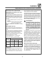
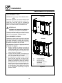
Leg Attachment
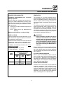
LEG OPTIONS
25" (635mm) Adjustable Leg
8Ć1/2" (216mm) Leg with
Casters, Adjustable Feet, or Seismic Feet
Figure 1
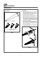
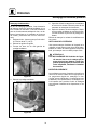
ATTACHMENT
1. Align the threaded stud on one of the front
legs to the bolt āholeā locatedāāā ināā ātheāā bottom ācorĆ
ner of the appliance. Turn the leg clockwise
and tighten to the nearest full turn.
2. Align the leg plate holes with the bolt holes.
Secure with the two 1/2" bolts provided.
3. Repeat the above steps with the other front
leg. If casters are used, install them with the
locking casters in the front of the oven. The rear
casters do not lock. Ensure that the locks are
set on the front casters.
4. Tip the oven up on the newly installed front
legs. If ācastersā are āused, checkā thatā the locksā
areā setā on ātheā front casters. āRepeat āthe above
steps for the rear legs.
5. Level the oven by screwing the adjustable feet
in or out as necessary.
Figure 2

Installation
7
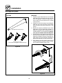
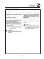
Caster Attachment
CASTERS FOR SINGLE OVENS
1. Attach the legs as described.
2. Pry the adjustable feet out of the legs.
3. Insert one caster into each leg as shown.
Tighten the lock nuts to secure the casters.
Adjustable
Leg Foot
Caster Assembly
Figure 3
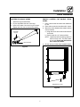
PROFILE CASTERS FOR DOUBLE STACK
OVENS
1. Place a level on the floor where the casters are
to rest.
2. Place shims under the low side until it is level.
3. Mount the shims between the casters and the
oven as follows:
a.) Align the shims and caster holes with the
bolt holes.
b.) Secure with the 1/2" bolts provided.
NOTE: Install them with the locking casters in
the front of the oven. The rear casters
do not lock. Ensure that the locks are
set on the front casters.
4. Tip the oven up on the newly installed casters.
Add shims
as necessary
Exaggerated for clarity
Floor
Figure 4

Installation
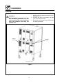
8
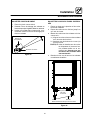
Stacking
WARNING!!
Stacking should be performed by qualiĆ
fied installation personnel only. The
ovens are heavy. Take care to use proper
tools and techniques when lifting and
stacking units.
1. Attach the legs or casters to the bottom oven.
See page 6 or 7.
2. Place the top oven on the bottom oven. Be
sure all four sides are flush.
3. Bolt the two ovens together from behind using
the stacking brackets.
Rear View HVĆ100E
Stacking
Bracket
Stacking
Bracket
Figure 5

Installation
9
Plumbing Connections
WATER CONNECTION
NOTE: Must use COLD WATER ONLY.
Connect the appliance to quality water via a presĆ
sure hose with 3/4" GHT (19mm) couplings. See
Figure 6 for connections. A shut off valve is to be
provided adjacent to the oven.
WARNING!!
Operating the appliance without a water
pressure regulator installed will invalidate
your warranty.
This product must be installed by a licensed
Plumber or Gas Fitter when installed within the
Commonwealth of Massachusetts.
DRAIN CONNECTION
The drain should be run to an open floor drain
avoiding flexible hose that could sag and allow
trapped water to accumulate. The customer must
supply the piping from the oven to the drain.
Specific water/drain connection for City of Los
Angeles
1. Each drain line from the appliance shall be
routed without dips or sags to terminate above
the flood level rim of an approved indirect waste
receptor.
2. The appliance shall be installed in accordance
with the manufacturer's printed instructions
and the LAPC and LAMC, 1999 editions.
3. A backflow protection device may be required
by local codes. If so, install on the potable water
system directly ahead of the appliance. The
backflow protection device shall be any of the
following: an approved pressure type vacuum
breaker installed at least 12" above the highest
point of use, a double check valve backflow preĆ
venter or a reduced pressure principal backflow
preventer.
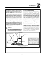
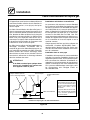
D
C
A
HVĆ100G
A
B
C
D
A = Electrical Connection
B = Gas Connection
C = Water Connection
Filtered Water highly recommended
D = Drain Connection
HVĆ100E
Figure 6

Installation
10
Electrical Connections
All Models
NOTE: Electrical connections must be performed
by a qualified installer only.
Before making any electrical connections to these
appliances, check that the power supply is adeĆ
quate for the voltage, amperage, and phase reĆ
quirements stated on the rating name plate
mounted on the appliance.
The circuit breaker that is used to provide power
to this appliance must have a minimum of .076"
(3mm) contact spacing. The circuit breaker must
meet all Local and National installation standards.
All appliances must be installed in accordance
with Local or National Electrical codes.
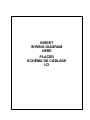
A wiring schematic is located on the inside of the
removeable side panel.
NOTE: Disconnect the power supply to the apĆ
pliance before servicing.
WARNING!!
Improper installation may invalidate your
warranty.
Electric Models
A strain relief for the power supply cord is provided.
The installer must supply a cord that meets all Local
and National installation standards.
Gas Models
U.S. and Canadian Installations
A power cord (115V units only) is supplied with a
plug attached. Plug the power cord into the deĆ
sired receptacle.
WARNING!!
If the supply cord is damaged, it must be
replaced by a special cord or assembly
available from the manufacturer or its serĆ
vice agent.

Installation
11
Gas Connections
GAS PIPING
A properly sized gas supply system is essential for
maximum oven performance. Piping should be
sized to provide a supply of gas sufficient to meet
the maximum demand of all appliances on the line
without loss of pressure at the equipment.
Example:
NOTE: BTU values in the following example are
for natural gas.
You purchase a BCXĆ14G to add to your existing
cook line.
1. Add the BTU rating of your current appliances.
Pitco Fryer 120,000 BTU
6 Burner Range 60,000 BTU
Deck Oven 50,000 BTU
Total 230,000 BTU
2. Add the BTU rating of the new oven to the toĆ
tal.
Previous Total 230,000 BTU
HVĆ100G 60,000 BTU
New Total 290,000 BTU
3. Measure the distance from the gas meter to
the cook line. This is the pipe length. Let's say
the pipe length is 30' (9 m) and the pipe size
is 1" (2.54 cm).
4. Use the appropriate table to determine the toĆ
tal capacity of your current gas piping.
The total capacity for this example is 375,000
BTU. Since the total required gas pressure,
290,000 BTU is less than 375,000 BTU, the
current gas piping will not have to be inĆ
creased.
NOTE: The BTU capacities given in the tables are
for straight pipe lengths only. Any elbows
or other fittings will decrease pipe capaciĆ
ties. For example: a schedule 40 1Ć1/2" ell
fitting has an equivalent capacity of 4.2"
(10.2 cm) of straight pipe. Contact your loĆ
cal gas supplier if you have any questions.
Maximum Capacity of Iron Pipe in Cubic Feet
of Natural Gas Per Hour
(Pressure drop of 0.5 Inch W.C.)
Pipe
Length
Nominal Size, Inches
L
eng
th
(ft)
3/4" 1" 1Ć1/4" 1Ć1/2" 2"
10 360 680 1400 2100 3950
20 250 465 950 1460 2750
30 200 375 770 1180 2200
40 170 320 660 990 1900
50 151 285 580 900 1680
60 138 260 530 810 1520
70 125 240 490 750 1400
80 118 220 460 690 1300
90 110 205 430 650 1220
100 103 195 400 620 1150
From the National Fuel Gas Code Part 10 Table 10Ć2
Maximum Capacity of Pipe in Thousands of
BTU/hr of Undiluted P.P. Gas at 11" W.C.
(Pressure drop of 0.5 Inch W.C.)
Pipe Length
(ft)
Inside Diameter, Inches
pg
(ft)
3/4" 1" 1Ć1/2"
10 608 1146 3525
20 418 788 2423
30 336 632 1946
40 287 541 1665
50 255 480 1476
60 231 435 1337
70 215 404 1241
80 198 372 1144
90 187 351 1079
100 175 330 1014
From the National Fuel Gas Code Part 10 Table 10Ć15

Installation
12
Gas Connections
PRESSURE REGULATION AND TESTING
The gas pressure to the appliance must be rated
for each appliance while the burners are on. A sufĆ
ficient gas pressure must be present at the inlet to
satisfy these conditions. Refer to the table below
for correct gas pressure.
Each appliance has been adjusted at the factory
to operate with the type of gas specified on the ratĆ
ing plate.
Each oven is supplied with a regulator to maintain
the proper gas pressure. The regulator is essenĆ
tial to the proper operation of the oven and
should not be removed.
DO NOT INSTALL AN ADDITIONAL REGULATOR
WHERE THE UNIT CONNECTS TO THE GAS
SUPPLY UNLESS THE INLET PRESSURE IS
GREATER THAN 14" W.C. (1/2 PSI) (37mbar).
The oven and its individual shutoff valve must be
disconnected from the gas supply piping system
during any pressure testing of that system at test
pressures in excess of 1/2 psig (3.45kPa).
The oven must be isolated from the gas supply
piping system by closing its individual manual
shutoff valve during any pressure testing of the
gas piping system at test pressures equal or less
than 1/2 psig (3.45kPa).
Prior to connecting the appliance, gas lines
should be thoroughly purged of all metal filings,
shavings, pipe dope, and other debris. After conĆ
nection, the appliance must be checked for corĆ
rect gas pressure.
U.S. and Canadian Installations
Installation must conform with local codes, or in
the absence of local codes, with the National Fuel
Gas Code, NFPA54/ANSI Z223.1-Latest Edition,
the Natural Gas Installation Code CAN/CGAĆ
B149.1 or the Propane Installation Code, CAN/
CGAĆB149.2 as applicable.
General Export Installations
Installation must conform with Local and National
installation standards. Local installation codes and/
or requirements may vary. If you have any questions
regarding the proper installation and/or operation of
your appliance, please contact your local distributor.
If you do not have a local distributor, please call
Blodgett Combi at 0011Ć802Ć860Ć3700.
GAS PRESSURE - HVĆ100G
Gas
Type
Inlet
Pressure
Orifice Size at Sea
Level
Manifold Pressure
Natural 7" W.C. .085" dia 3.5" W.C.
Propane 14" W.C. .063" dia 10" W.C.

Installation
13
Gas Hose Restraint
If the appliance is mounted on casters, a commerĆ
cial flexible connector with a minimum of 3/4" (1.9
cm) inside diameter must be used along with a
quick connect device.
A restraint must be used to limit the movement of
the appliance so that no strain is placed upon the
flexible connector. The restraint should be fasĆ
tened to the base frame of the oven as close to the
flexible connector as possible. It should be short
enough to prevent any strain on the connector.
With the restraint fully stretched the connector
should be easy to install and quick connect.
The restraint (ie: heavy gauge cable) should be atĆ
tached without damaging the building. DO NOT
use the gas piping or electrical conduit for the atĆ
tachment of the permanent end of the restraint!
Use anchor bolts in concrete or cement block. On
wooden walls, drive hi test wood lag screws into
the studs of the wall.
WARNING!!
If the restraint is disconnected for any reaĆ
son it must be reconnected when the apĆ
pliance is returned to its original position.
U.S. and Canadian installations
The connector must comply with the Standard for
Connectors for Movable Gas Appliances, ANSI
Z21.69 or Connectors For Moveable Gas ApĆ
pliances CAN/CGAĆ6.16 and a quick disconnect
device that complies with the Standard for QuickĆ
Disconnect Devices for Use With Gas Fuel, ANSI
Z21.41 or Quick Disconnect For Use With Gas Fuel
CAN 1Ć6.9. Adequate means must be provided to
limit the movement of the appliance without deĆ
pending on the connection and the quick disconĆ
nect device or its associated piping.
A drip leg must be used at each appliance. Refer
to NFPA54/ANSI Z223.1 Ć Latest Edition (National
Fuel Gas Code) for proper drip leg installation.
General export installations
Installation must conform with Local and National
installation standards. Local installation codes and/
or requirements may vary. If you have any questions
regarding the proper installation and/or operation of
your appliance, please contact your local distributor.
If you do not have a local distributor, please call
Blodgett Combi at 0011Ć802Ć860Ć3700.
Gas Supply Line
Gas Hose
Quick Connect
Installation of Gas Hose and Restraint
(Single Section Shown)
Attachment Plate
(secure with leg mount bolt)
IMPORTANT: Cable restraint should
be fastened as close as possible to the
flexible connector and short enough to
prevent any strain on the flexible conĆ
nector.
At maximum stretch of shortened reĆ
straint, the flexible connector should
be easy to install and quick to connect.
Restraint
Figure 7

Operation
14
Safety Information for Gas Units
THE INFORMATION CONTAINED IN THIS SECĆ
TION IS PROVIDED FOR THE USE OF QUALIFIED
OPERATING PERSONNEL. QUALIFIED OPERATĆ
ING PERSONNEL ARE THOSE WHO HAVE
CAREFULLY READ THE INFORMATION CONĆ
TAINED IN THIS MANUAL, ARE FAMILIAR WITH
THE FUNCTIONS OF THE OVEN AND/OR HAVE
HAD PREVIOUS EXPERIENCE WITH THE OPĆ
ERATION OF THE EQUIPMENT DESCRIBED. ADĆ
HERENCE TO THE PROCEDURES RECOMĆ
MENDED HEREIN WILL ASSURE THE
ACHIEVEMENT OF OPTIMUM PERFORMANCE
AND LONG, TROUBLEĆFREE SERVICE.
Please take the time to read the following safety
and operating instructions. They are the key to the
successful operation of your Blodgett Combi apĆ
pliance.
SAFETY TIPS
For your safety read before operating
What to do if you smell gas:
D DO NOT try to light any appliance.
D DO NOT touch any electrical switches.
D Use an exterior phone to call your gas supplier
immediately.
D If you cannot reach your gas supplier, call the
fire department.
What to do in the event of a power failure:
D Turn all switches to off.
D DO NOT attempt to operate the appliance until
the power is restored.
NOTE: In the event of a shutĆdown of any kind, alĆ
low a five (5) minute shut off period before
attempting to restart the oven.
General safety tips:
D DO NOT use tools to turn off the gas control. If
the gas cannot be turned off manually do not try
to repair it. Call a qualified service technician.
D If the oven needs to be moved for any reason,
the gas must be turned off and disconnected
from the appliance before removing the reĆ
straint cable. Reconnect the restraint after the
oven has been returned to its original location.
D DO NOT remove the control panel cover unless
the oven is unplugged.

Operation
15
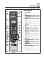
Standard Control
3
6
4
7
1
5
11
12
8
9
11
2
13
Figure 8
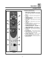
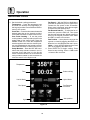
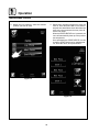
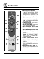
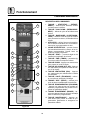
CONTROLS IDENTIFICATION
1. MODE SELECTOR SWITCH - turns power
to the oven on or off. Allows selection of Hydro
Low, Hydro High, Hot Air, or Cool Down
Modes.
2. DISPLAY - displays time and temperature inĆ
formation.
3. TEMPERATURE DIAL - used to set desired
cooking temperature.
4. HEAT LAMP - lights when the oven is calling
for heat
5. TIMER LED - lights when the cook time is
displayed
6. PROBE ACTUAL LED - lights when the actuĆ
al probe temperature is displayed
7. PROBE SETPOINT LED - lights when the
core setpoint temperature is displayed
8. TIMER/PROBE KNOB - use to select and
set either cook time or probe temperature
9. LIGHTS KEY - press to turn the oven lights
on and off
10. FAN SPEED KEY - used to select fan speed.
11. CAVITY VENT KEY - used to open or close
vent to release humidity from cavity.
12. PROBE CONNECTION - used to connect
the core temperature probe to the control.
13. CIRCUIT BREAKER - Used to turn power to
the unit on or off.

Operation
16
Standard Control
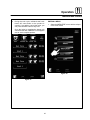
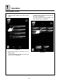
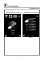
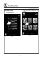
TIMER COOKING
1. Press the TIMER/PROBE KNOB (8) to select
the timer mode. The TIMER LED lights.
2. Turn the MODE SELECTOR Switch (1) to the
desired function.
3. Set the TEMPERATURE DIAL (3) to the deĆ
sired cook temperature.
4. When the oven has reached the cook temperĆ
ature, load the product.
5. Rotate knob to enter the desired cook time in
the display. You can clear the display by rotatĆ
ing counter clockwise. The timer begins on its
own.
6. The temperature, time, and mode can be alĆ
tered at any time during the cooking process.
7. When the timer reaches 00:00, the buzzer
sounds. Press or rotate the TIMER/PROBE
KNOB (8) counter clockwise to silence the
buzzer. Remove the product.
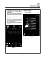
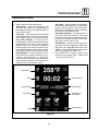
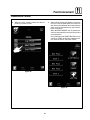
PROBE COOKING
1. Press the TIMER/PROBE knob (8) to select
the probe setpoint mode. The PROBE SETĆ
POINT LED (7) lights.
2. Rotate the knob to enter the desired final cook
temperature in the display.
3. Insert the core probe into the product. Load
product into the oven and close the door. Be
sure that the terminal end of the core probe is
outside of the oven and clear of the door.
4. Connect the core probe to the PROBE CONĆ
NECTION (12) at the bottom of the control.
5. The display gives the actual core probe temĆ
perature by pressing the TIMER/PROBE knob
(8) again.
6. When the product reaches the final cook temĆ
perature the buzzer sounds.
COOL DOWN
NOTE: The unit can be cooled down rapidly.
1. To cool down the oven cavity, open the door
and select Cool Down on the MODE SELECĆ
TOR Switch (1).
La page est en cours de chargement...
La page est en cours de chargement...
La page est en cours de chargement...
La page est en cours de chargement...
La page est en cours de chargement...
La page est en cours de chargement...
La page est en cours de chargement...
La page est en cours de chargement...
La page est en cours de chargement...
La page est en cours de chargement...
La page est en cours de chargement...
La page est en cours de chargement...
La page est en cours de chargement...
La page est en cours de chargement...
La page est en cours de chargement...
La page est en cours de chargement...
La page est en cours de chargement...
La page est en cours de chargement...
La page est en cours de chargement...
La page est en cours de chargement...
La page est en cours de chargement...
La page est en cours de chargement...
La page est en cours de chargement...
La page est en cours de chargement...
La page est en cours de chargement...
La page est en cours de chargement...
La page est en cours de chargement...
La page est en cours de chargement...
La page est en cours de chargement...
La page est en cours de chargement...
La page est en cours de chargement...
La page est en cours de chargement...
La page est en cours de chargement...
La page est en cours de chargement...
La page est en cours de chargement...
La page est en cours de chargement...
La page est en cours de chargement...
La page est en cours de chargement...
La page est en cours de chargement...
La page est en cours de chargement...
La page est en cours de chargement...
La page est en cours de chargement...
La page est en cours de chargement...
La page est en cours de chargement...
La page est en cours de chargement...
La page est en cours de chargement...
La page est en cours de chargement...
La page est en cours de chargement...
La page est en cours de chargement...
La page est en cours de chargement...
La page est en cours de chargement...
La page est en cours de chargement...
La page est en cours de chargement...
La page est en cours de chargement...
La page est en cours de chargement...
La page est en cours de chargement...
La page est en cours de chargement...
-
 1
1
-
 2
2
-
 3
3
-
 4
4
-
 5
5
-
 6
6
-
 7
7
-
 8
8
-
 9
9
-
 10
10
-
 11
11
-
 12
12
-
 13
13
-
 14
14
-
 15
15
-
 16
16
-
 17
17
-
 18
18
-
 19
19
-
 20
20
-
 21
21
-
 22
22
-
 23
23
-
 24
24
-
 25
25
-
 26
26
-
 27
27
-
 28
28
-
 29
29
-
 30
30
-
 31
31
-
 32
32
-
 33
33
-
 34
34
-
 35
35
-
 36
36
-
 37
37
-
 38
38
-
 39
39
-
 40
40
-
 41
41
-
 42
42
-
 43
43
-
 44
44
-
 45
45
-
 46
46
-
 47
47
-
 48
48
-
 49
49
-
 50
50
-
 51
51
-
 52
52
-
 53
53
-
 54
54
-
 55
55
-
 56
56
-
 57
57
-
 58
58
-
 59
59
-
 60
60
-
 61
61
-
 62
62
-
 63
63
-
 64
64
-
 65
65
-
 66
66
-
 67
67
-
 68
68
-
 69
69
-
 70
70
-
 71
71
-
 72
72
-
 73
73
-
 74
74
-
 75
75
-
 76
76
-
 77
77


Blodgett HV-100E Mode d'emploi
- Taper
- Mode d'emploi
- Ce manuel convient également à
dans d''autres langues
Documents connexes
-
Blodgett B14G spécification
-
Blodgett BCX -14G Mode d'emploi
-
-
-
Blodgett ZEPHAIRE-G Mode d'emploi
-
-
-
-
-
Blodgett HV-100E Le manuel du propriétaire