Ideal 1000A AC/DC TRMS TightSight® Clamp Meter Mode d'emploi
- Catégorie
- Testeurs de réseau câblé
- Taper
- Mode d'emploi
Ce manuel convient également à

#61-763, #61-765
#61-773, #61-775
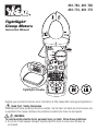
TightSight®
Clamp Meters
Instruction Manual
Register your product and access more information at http://www.idlim.net/support/registration/.
Read First: Safety Information
Understand and follow operating instructions carefully. Use the meter, test leads and all accessories only
as specified in this manual; otherwise, the protection provided by the meter can be impaired.
WARNING
To avoid possible electric shock, personal injury or death, follow these guidelines:
• Do not use if meter appears damaged. Visually inspect the meter to ensure case and jaws are
not cracked.
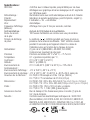
600V1000V
61-766
COM
V/
CAT. IV 600V
CAT. III 1000V
MAX
1000V
750V
APO
AC
A
DCAC AMPS
660
INRUSH
1000
TightSight® Display

2
• Inspect and replace test leads if insulation is damaged, metal is exposed, or probes are cracked. Pay
particular attention to the insulation surrounding the connectors.
• To preserve the safety rating of this product, use only test leads with a minimum rating of
CAT III 600V. Do not use improvised connections that could present a safety hazard.
• Always ensure the meter, test leads and all accessories meet or exceed the measurement category
required in the working environment. (i.e. CAT rating)
• Note that the measurement category and voltage rating of combinations of the meter, the test leads,
and the accessories is the lowest of the individual components.
• Do not use meter if it operates abnormally as protection may be impaired.
• Do not use during electrical storms or in wet weather.
• Do not use around explosive gas, dust, vapor, or in damp or wet environments. Do not submerge or
expose the meter to water and do not use if the meter has ever been exposed to water or other fluids.
• Do not apply more than the rated voltage or amperage
• Remove the test leads from the input jacks before measuring current.
• Replace battery as soon as battery indicator appears to avoid false readings.
• Remove the test leads from the meter prior to removing battery cover.
• Do not use without the battery and battery cover properly installed.
• Do not attempt to repair this unit as it has no user-serviceable parts.
• Use the proper terminals, functions and range for your measurements.
• Never ground yourself when taking electrical measurements.
• Connect the black common lead to ground or neutral before applying the red test lead to potential
voltage. Disconnect the red test lead from the voltage first.
• Keep fingers behind the guard rings of the probe tips.
• Hold the clamp behind the tactile barrier.
• Voltages exceeding 30VAC or 60VDC pose a shock hazard so use caution.
• Remove lead set when measuring current.
• Remove the batteries for storage or if the meter will not be used for longer than one month.
Battery leakage will compromise the safety of the meter and cause damage to internal components.
CAUTION
To protect yourself, think “Safety First”:
• Comply with local and national safety codes.
• Use appropriate personal protective equipment such as face shields, insulating gloves, insulating
boots, and/or insulating mats.
• Before each use:
- Perform a continuity test by touching the metal tips of the test leads together to verify the
functionality of the battery and test leads.
- Use the 3 Point Safety Method. (1) Verify meter operation by measuring a known voltage.
(2) Apply meter to the circuit under test. (3) Return to the known live voltage again to
ensure proper operation.
• Always work with a partner.

3
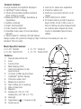
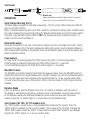
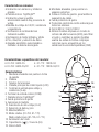
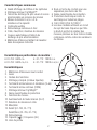
Features
1. Tapered jaws w/hook tip
2. Lever
3. Function Dial
4. Main Display (LCD)
5. Volts and resistance (V-Ω)
input terminal
6. Common (COM) input terminal
7. TightSight® bottom display
8. Protective rubber boot
9. Measuring Functions
10. High Voltage (Hi-V) warning
11. Data & Peak Hold
12. Max/min
13. Relative (61-763, 61-773)
Relative/Zero (61-765, 61-775)
14. Backlight
15. Capacitance ( ) / Frequency (Hz)
16. Tactile barrier
Common Features:
1
10
3
15
4
5
9
16
12
13
14
6
87
211
• Large numbers and symbols displayed
• TightSight® bottom display
• Visual and selectable audible indication
when voltage is present
• Measures AC/DC Voltage, Resistance &
Capacitance
• Audible continuity
• Bright, bold backlight
• Peak, max/min, data hold
• Selectable Auto power off and low battery
indicator
• Tapered jaws for reaching into tight spaces
• Hook tip for easier wire separation
• Protective rubber boot
• Electronic overload protection on all
ranges
• Cat IV-600V/Cat III-1000V
• All models employ a High Frequency
Reject (HFR) circuit to filter noise or
help in making accurate measurements
on complex wave shapes like those
found on Adjustable Speed Drives
(ASDs)
Always replace the protective Category Caps if removal is necessary for use in a
standard 120 volt outlet.
Model Specific Features:
• 61-763: 660AAC • 61-773: 1000A AC
• 61-765: 660A AC/DC • 61-775: 1000A AC/DC

4
APO HOLD MAX MIN P + P -
mVA
nm F
kM
Hz
AC
DC
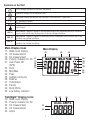
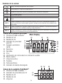
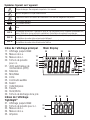
Main Display Icons
17. 9999 count display
18. AC measurement
19. DC measurement
20. Polarity indicator for DC
21. Auto Power Off
(APO)
22. Hold
23. Min/Max
24. Peak
25. Audible continuity
26. Relative
27. Volts/Amps
28. Farads
29. Hertz/Ohms
30. Low battery indicator
TightSight® Display Icons
31. 9999 count display
32. Polarity indicator for DC
33. DC measurement
34. AC measurement
35. Amps
Main Display
DCAC AMPS
32
31
33 34 35
27
30
26
28
29
25
2223 24
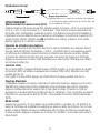
Symbols on the Unit
17
18
19
20
21
Risk of Danger. Important Information. See Manual.
Hazardous voltage. Risk of electrical shock.
Application around and removal from Hazardous Live conductors is permitted.
AC (Alternating Current)
DC (Direct Current)
Earth Ground
CAT II Measurement Category II applies to test and measuring circuits connected directly to utilization
points (socket outlets and similar points) of the low-voltage installation
CAT III Measurement Category III applies to measuring circuits connected to the distribution part of the
building’s low-voltage installation
CAT IV Measurement Category IV applies to test and measuring circuits connected at the source of the
building’s low-voltage installation
~
...

Test Leads
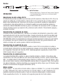
OPERATION:
High Voltage Warning (HI-V)
The meter beeps and lights an LED when measuring > 30V AC on the VAC function and >30V DC
when on the VDC function.
Notes: This feature does not work in the Ohm, capacitor, continuity or clamp modes. Audible indica-
tion can be disabled by pressing and holding the Max/min button while turning the function switch
from OFF to any desired Function. Wait for Hb to be displayed and then release the button. To
enable, turn the unit off and back on.
Data Hold Feature
Press the Hold button on the side of the meter to toggle in and out of the data hold mode. “HOLD”
appears in the upper left of the meter display when data hold is active. Use the data hold feature to
lock a measurement reading on the display. Press the Hold button again to unlock the display and
obtain a real-time reading.
Peak Feature
In PEAK mode, the meter displayed the PEAK value of AC Volts or Current measurement.
PEAK function is enabled by Depressing the PEAK HOLD button for > 2 seconds.
To Exit PEAK Mode Depress the PEAK HOLD button again for > 2 seconds.
Max/Min Feature
The Max/Min records the maximum and minimum measured value. Press the Max/Min button to
activate this feature and to toggle between max, and Min readings. The unit will continually capture
max and min values over time. Depressing the max/min button for >2 sec. exits the mode. Note:
To record max/min values over a time period >30 min, the Auto Power Off (APO) feature must be
defeated.
Relative Mode
Press “∆” button to enter the Relative mode. The “∆” symbol is displayed, and the value on
the display is subtracted and stored as a reference value. In the Relative mode, the value shown
on the display is always the difference between the stored reference value and the present
reading. Press the “∆” button again for > 2 seconds to exit the Relative mode.
Zero Feature (61-765, 61-775 models only)
The “ZERO” button is used to zero out the display before measuring DC current. Press the
“ZERO” button to subtract out the non-zero number. Then, measure the DC amps. Pressing the
“ZERO” button again causes the “ZERO” to flash and the original offset number to be displayed.
Depress the “ZERO” button for >2 sec. to exit this mode.
5
Guard ring
CAT IV 600V
CAT III 1000V CAT II 1000V
Always replace the protective Category Caps if removal is
necessary for use in a standard 120 volt outlet.

6
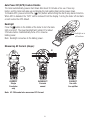
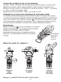
Note: 61-765 model also measures DC Current.
INCORRECT
Currents
cancel
CORRECT
Single
Conductor
only
CORRECT
Use with
line splitter
Auto Power Off (APO) Feature Disable
The meter automatically powers itself down after about 30 minutes of no use. Press any
button, and the meter will wake up and display the last reading taken before power down.
To Disable APO, press and hold the ( / Hz) button while turning the dial to any desired function.
When APO is defeated, the “APO” will be removed from the display. Turning the meter off and back
on will restore the APO default.
Backlight
Press the button in the middle of the meter to turn the back-
light on and off. The green backlight will remain lit for about
3 minutes before it automatically turns off to conserve
battery power.
Note: Backlight consumes 4x the battery power .
Measuring AC Current (Amps):
INRUSH
Backlight on in
all functions.
H
N

7
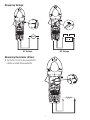
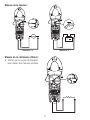
Measuring Resistance (Ohms):
• Verify the circuit is de-energized to
obtain accurate measurements.
Measuring Voltage:
AC Voltage DC Voltage

8
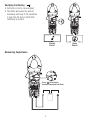
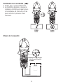
Verifying Continuity ( ):
• Verify the circuit is de-energized.
• The meter will sense the level of
resistance and beep if the resistance
is less than 30 Ω to confirm that
continuity is present.
Closed
Circuit
Open
Circuit
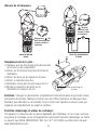
Measuring Capacitance
Press / Hz to toggle
between Capacitance & Ohms

w/Clamp Head
Press / Hz to toggle
between AC current &
Frequency
w/Test Leads
Press / Hz
to toggle
between ACV
& Frequency
9
Measuring Frequency
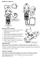
Battery Replacement:
• Ensure test leads are disconnected from
circuit or components.
• Remove test leads from input jacks
on meter.
• Remove the two screws from the
battery cap.
• Remove the battery cap.
• Replace battery with a new 9V battery.
• Assemble the battery cap to the
meter and re-tighten the screws.
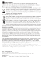
Maintenance:
Switch off and disconnect the meter completely before carrying out any maintenance. Clean the
case with a damp cloth and mild detergent. Do not use abrasives or solvents. Keep away from
liquids and ensure the meter is completely dry before use.
Service and Replacement Parts:
This unit has no user-serviceable parts.
For replacement parts or to inquire about service information contact IDEAL INDUSTRIES, INC.
at 1-877-201-9005 or visit our website www.idealind.com.
Replacement boot is
available.

10
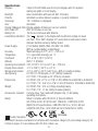
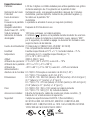
Specifications:
Displays: 4 digit LCD with 9999 counts for both displays with 41 segment
analog bar graph on front display
Backlight: Green illumination with auto-off after 3 minutes
Polarity: Automatic, positive implied, negative (-) polarity indication.
Overrange: “OL” indication is displayed.
Zero: Automatic
Display (Measure) Rate: Display updates 2 times per second, nominal.
Auto Power Off: After 30 minutes of non-use.
Battery Life: 100 hours continuous with Alkaline
Low Battery Indication: The “ “ appears in the display with insufficient voltage for about
one hour. Then “bAtt” displays for 5 seconds and unit powers down.
Indicator duration varies by battery brand.
Power Supply: (1) 9V battery (NEDA 1604, JIS 006P, IEC 6F22)
With an isolated battery compartment.
Accuracy: Stated accuracy at 23°C ±5°C, <75% R.H.
Temperature 0.1 x (specified accuracy) per °C,
Coefficient: (0°C to 18°C, 28°C to 50°C).
Altitude: 6561.7 ft. (2000m)
Operating Environment: 32°F to 122°F (0°C to 50°C) at < 70% R.H.
Display Environment: -4°F to 158°F (-20°C to +70°C)
Storage Environment: -4°F to 140°F (-20°C to 60°C) at < 80% R.H. without battery
Jaw Opening: 61-763/ 61-765 accepts a 1.42” (36mm) conductor
61-773/61-775 accepts a 2.0” (51mm) conductor
Dimensions: 61-763/61-765: 8.7”H x 3.1”W x 1.8”D (222mmH x 80mmW x 45.5mmD)
61-773/61-775: 10.6”H x 4.1”W x 1.9”D (270mmH x 103mmW x 48.5mmD)
Weight: 61-763/61-765: 12.3 oz. (350g) including battery
61-773/61-775: 1.1 lbs. (500g) including battery
Accessories included: Carrying Case, Test Leads with alligator clip, (1) 9V battery,
operating instructions.
Safety: Safety: Complies with (UL61010-1) (Second Edition),
IEC 61010-2-032, IEC 61010-031. EN61010-1, EN61010-2-032,
EN61010-031 specifications, CAN/CSA C22.2 no. 1010.1-92 and
CAN/CSA C22.2 No. 1010.2.032-96 Cat IV-600V/Cat III-1000V.
Double Insulation
Instrument has been evaluated and complies with insulation category IV (overvoltage category IV).
Pollution degree 2 in accordance with IEC-644. Indoor use.
N12966

11
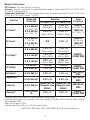
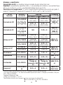
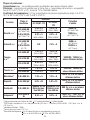
Ranges & Accuracies:
AC Converter: All models are true rms sensing.
Accuracy: Accuracy is specified as +/-(a percentage of the reading + a fixed count) at 23°C±5°C (73.4°F ± 9°F),
less than 75% relative humidity.
Temperature Coefficient: 0.1 times the applicable accuracy specification per degree C from 0°C to 18°C and
28°C to 50°C (32°F to 64°F and 82°F to 122°F)
Function Range and
Resolution
Accuracy Input
Protection
61-763/61-773 61-765/61-775
AC Current1
0.0 to 660.0A
(61-763/61-765)
0.0 to 999.9A
(61-773/61-775)
2.0% + 5
(45Hz to 60Hz)
2.0% + 5
(20Hz to 100Hz)
660A AC
(61-763/61-765)
1000A AC
(61-773/61-775)
6.0% + 5
(60Hz to 400Hz)
6.0% + 5
(100Hz to 400Hz)
DC Current
0.0 to 660.0A
(61-765)
0.0 to 999.9A
(61-775)
N/A 2.0% + 5
660A DC
(61-765 only)
1000A DC
(61-775 only)
AC Voltage1,2
0.0 to 600.0V 1.0% + 5
(45Hz to 100Hz)
1.0% + 5
(20Hz to 100Hz)
1000VDC /
750VAC RMS
0.0 to 750.0V 1.5% + 5
(45Hz to 100Hz)
1.5% + 5
(45Hz to 100Hz)
0.0 to 750.0V 6.0% + 5
(100Hz to 400Hz)
6.0% + 5
(100Hz to 400Hz)
DC Voltage2 0.0-600.0V 1.0% +5 1.0% +5 1000VDC /
750VAC RMS
0.0 to 999.9V 1.5% + 5 1.5% + 5
Resistance30.0 to 999.9Ω1.5% + 5 1.5% + 5 600V DC/AC
RMS
Capacitance 0.0 to 999.9µF 5.0% +15 5.0% +15 600V DC/AC
RMS
Continuity 0.0 to 999.9Ω
Audible at < 30
Response time
500mS
Audible at < 30
Response time
500mS
600V DC/AC
RMS
Frequency420.0 to 400.0
Hz 0.5% + 5 0.5% + 5 1000VDC /
750VAC RMS
*Accuracy stated for crest factor ≤ 1.5 at full scale and ≤ 3 at half scale.
1Peak Hold
response time < 1ms; Accuracy is ±(5% rdg + 15 digits) @ 45-60Hz; >10V for VAC and >10A for A AC/DC
2Input impedance: 1MΩ.
3Open circuit voltage ≈ 1.2V DC
4Frequency Sensitivity: ≥ 5V rms on AC Volts using test leads
≥ 5AAC (20 to 100Hz) and ≥ 10AAC (100 to 400Hz) on AC Amps using clamp head.

12
Dispose of waste electrical and electronic equipment
In order to preserve, protect and improve the quality of environment, protect human health and
utilize natural resources prudently and rationally, the user should return unserviceable product to
relevant facilities in accordance with statutory regulations. The crossed-out wheeled bin indicates
the product needs to be disposed separately and not as municipal waste.
Disposal of used batteries/accumulators!
The user is legally obliged to return used batteries and accumulators. Disposing used batteries
in the household waste is prohibited! Batteries/accumulators containing hazardous substances
are marked with the crossed-out wheeled bin. The symbol indicates that the product is forbid-
den to be disposed via the domestic refuse. The chemical symbols for the respective hazardous
substances are Cd = Cadmium, Hg = Mercury, Pb = Lead.
You can return used batteries/accumulators free of charge to any collecting point of your local
authority, our stores, or where batteries/accumulators are sold. Consequently you comply with
your legal obligations and contribute to environmental protection.
Warranty Statement:
This tester is warranted to the original purchaser against defects in material and workmanship for two years
from the date of purchase. During this warranty period, IDEAL INDUSTRIES, INC. will, at its option, replace
or repair the defective unit, subject to verification of the defect or malfunction. Your original receipt from an
authorized distributor of IDEAL INDUSTRIES, INC. is your proof of purchase. Register your product at:
http://www.idlim.net/support/registration/.
Any implied warranties arising out of the sale of an IDEAL product, including but not limited to
implied warranties of merchantability and fitness for a particular purpose, are limited to the above. The
manufacturer shall not be liable for loss of use of the instrument or other incidental or consequential
damages, expenses, or economic loss, or for any claim or claims for such damage, expenses or economic
loss.
State laws vary, so the above limitations or exclusions may not apply to you. This warranty gives you
specific legal rights, and you may also have other rights which vary from state to state.
Warranty does not cover batteries.

13
600V1000V
61-766
COM
V/
CAT. IV 600V
CAT. III 1000V
MAX
1000V
750V
APO
AC
A
DCAC AMPS
660
INRUSH
1000
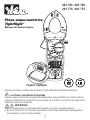
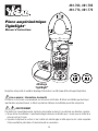
Pantalla TightSight®
#61-763, #61-765
#61-773, #61-775
Pinza amperométrica
TightSight®
Manual de Instrucciones
Registre su producto y acceda a más información en http://www.idlim.net/support/registration/.
Lea Primero: Información de Seguridad
Entienda y siga las instrucciones de operación cuidadosamente. Use el multímetro, las sondas y todos los
accesorios únicamente como se especifica en este manual; de lo contrario, la protección que proporciona el
multímetro puede verse perjudicada.
ADVERTENCIA
Para evitar posibles riesgos de descarga eléctrica, lesiones o la muerte, siga estas directrices:
• No use el multímetro si el mismo parece estar dañado. Inspecciónelo visualmente para asegurarse de
que la cubierta y la pinza no estén quebradas.

14
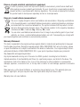
• Inspeccione y reemplace los cables si el aislamiento está dañado, hay metal expuesto o las sondas están
quebradas. Preste atención especial al aislante alrededor de los conectores.
• Para conservar la calificación de seguridad de este producto, utilice solamente cables de prueba con
una calificación mínima de CAT III 600 V. No utilice conexiones improvisadas que podrían presentar un
peligro para la seguridad.
• Siempre asegúrese de que el multímetro, las sondas y todos los accesorios cumplan o excedan la
categoría de medición necesaria en el ambiente de trabajo. (Por ejemplo, clasificación CAT)
• Tome nota de que la categoría de medición y la clasificación de voltaje de combinaciones del multímetro,
la sondas y los accesorios es la más baja de los componentes individuales.
• No utilice el medidor si funciona anormalmente, ya que la protección puede estar afectada.
• No use el multímetro durante tormentas eléctricas o en clima húmedo.
• No use cerca de gases explosivos, polvo, vapor o en ambientes mojados o húmedos. No sumerja ni
exponga el medidor al agua y no lo use si el medidor ha estado expuesto alguna vez al agua o a otros
líquidos.
• No aplique voltajes o amperajes superiores a las nominales.
• Quite las sondas de los puertos de entrada antes de medir corriente.
• Reemplace la batería tan pronto aparezca el indicador de carga de batería baja, para evitar las lecturas
falsas.
• Retire las sondas del multímetro antes de quitar la tapa de la batería.
• No use el multímetro sin la batería, ni sin la tapa de la batería correctamente instalada.
• No intente reparar esta unidad ya que no tiene piezas reparables por el usuario.
• Use las terminales, funciones y rangos apropiados para sus medidas.
• No se conecte a tierra cuando tome medidas eléctricas.
• Conecte la sonda negra común a tierra o a neutro antes de tocar la sonda roja a voltaje potencial.
Desconecte la sonda roja del voltaje primero.
• Mantenga los dedos detrás de los anillos protectores en las puntas de las sondas.
• Mantenga el producto tras la barrera táctil.
• Los voltajes superiores a 30 VCA o 60 VCD representan un riesgo de descarga eléctrica, así que tenga
precaución.
• Quite los cables de prueba cuando mida la corriente.
• Quita las baterías al almacenar o si el medidor no se utilizará durante más de un mes. Las fugas de batería
comprometerán la seguridad del medidor y causarán daños a los componentes internos.
PRECAUCIÓN
Para protegerse, piense “¡La seguridad primero!”:
• Cumpla con los requisitos de seguridad locales y nacionales.
• Use equipos de protección personal apropiados, tales como, caretas, guantes aislantes,
calzado y/o alfombras aislantes.
• Antes de cada uso:
- Realice una prueba de continuidad tocando las puntas metálicas de los cables de prueba
para verificar la funcionalidad de la batería y los cables de prueba.
- Use el Método de Seguridad de 3 Puntos. (1) Verifique el funcionamiento del multímetro
midiendo un voltaje conocido. (2) Aplique el multímetro al circuito en prueba. (3) Vuelva
al voltaje conectado conocido para asegurar el funcionamiento correcto.
• Siempre trabaje con un compañero.

15
Características
1. Mordazas ahusadas con punta en forma
de gancho
2. Palanca
3. Selector de funciones
4. Pantalla principal de cristal líquido (LCD)
5. Terminal de entrada para voltaje y
resistencia (V-Ω)
6. Terminal de entrada común (COM)
7. Pantalla inferior TightSight®
8. Funda protectora de goma
9. Funciones de medida
10. Advertencia de alto voltaje (Hi-V)
11. Retención de datos y pico
12. Máximo/Mínimo
13. Modo relativo (61-763, 61-773)
Modo relativo/cero (61-765, 61-775)
14. Iluminación de fondo
15. Capacitancia ( ) / Fruencia (Hz)
16. Barrera táctil
1
10
11
3
15
4
5
9
12
13
14
6
87
2
Características comunes:
• Indicación con números y símbolos
grandes
• Pantalla inferior TightSight™
• Indicación visual y audible
seleccionable cuando hay presencia de
voltaje
• Medida de voltaje de CA/CC, resistencia
y capacitancia
• Verificación de continuidad con
indicación audible
• Iluminación de fondo brillante y nítida
• Pico, máx/mín y retención de datos
• Apagado automático seleccionable e
indicador de batería descargada
• Mordazas ahusadas, para penetrar en
espacios estrechos
• Punta en forma de gancho, para facilitar la
separación de cables
• Funda protectora de goma
• Protección electrónica contra sobrecarga en
todos los alcances
• Cat IV-600 V / Cat III-1000 V
• Ambos modelos emplean un circuito de
rechazo de alta frecuencia (HFR) para filtrar
el ruido o contribuir a realizar medidas
exactas de ondas de formas complejas
como las que se encuentran en los
variadores de velocidad ajustables (ASD)
Características específicas del modelo:
• 61-763: 660A CA • 61-773: 1000A CA
• 61-765: 660A CA/CC • 61-775: 1000A CA/CC

16
Íconos de la pantalla principal
17. Pantalla de 9999 unidades
18. Medida de CA
19. Medida de CC
20. Indicador de polaridad
para CC
21. Apagado automático
(APO)
22. Retención
23. Mín/Máx
24. Pico
25. Verificación de continuidad con indicación audible
26. Modo relativo
27. Amperios/voltios
28. Faradios
29. Hertzios/ohmios
30. Indicador de batería descargada
Íconos de la pantalla TightSight®
31. Pantalla de 9999 unidades
32. Indicador de polaridad para CC
33. Medida de CC
34. Medida de CA
35. Amperios
DCAC AMPS
32
31
33 34 35
APO HOLD MAX MIN P + P -
mVA
nm F
kM
Hz
AC
DC
Main Display
17
18
19
20
21 27
30
26
28
29
25
2223 24
Símbolos de la unidad
Riesgo. Información Importante. Vea el Manual.
Voltaje peligroso. Peligro de choque eléctrico.
Se permite la aplicación y el retiro de alrededor y de Conductores Energizados.
CA (Corriente Alterna)
CD (Corriente Directa)
Tierra
CAT II Categoría de Medición II aplica a la prueba y medición de circuitos directamente conectados a
puntos de utilización (tomacorrientes y puntos similares) de la instalación de la red eléctrica de
bajo voltaje
CAT III Categoría de Medición III aplica a la medición de circuitos conectados a la parte de distribución
de la instalación de la red eléctrica de bajo voltaje del edificio
CAT IV Categoría de Medición IV aplica a la prueba y medición de circuitos conectados a la fuente de la
instalación de la red eléctrica de bajo voltaje del edificio
~
...

17
Sondas
OPERACIÓN:
Advertencia de alto voltaje (Hi-V)
El instrumento produce un pitido y se enciende un LED cuando se mide más de 30 V CA en la
función de voltaje de corriente alterna y más de 30 V CC en la función de corriente continua.
Notas: Esta característica no funciona en los modos de medida de resistencia, capacitancia,
continuidad o pinza amperométrica. La indicación audible se puede desactivar pulsando y
reteniendo el botón Max/Min mientras se gira el conmutador de funciones de OFF a cualquier
función deseada. Espere que aparezca Hb y entonces suelte el botón. Para activarla, apague y
encienda la unidad.
Característica de retención de datos
Presione el botón Hold (Retención), ubicado en el costado del instrumento, para entrar y salir
sucesivamente del modo de retención de datos. Cuando la función de retención de datos está
activa, aparece en la parte superior izquierda de la pantalla del instrumento la leyenda ‘HOLD’
(RETENCIÓN). Utilice la característica de retención de datos para fijar la lectura de una medida
en la pantalla. Para que la indicación de la pantalla deje de estar fija y pueda obtenerse una
lectura en tiempo real, vuelva a pulsar el botón Hold (Retención).
Característica de medición de pico
En el modo PEAK (PICO), el instrumento muestra el valor PICO de la medición de voltaje o
corriente alterna. Esta función se activa manteniendo pulsado el botón PEAK HOLD durante más
de 2 segundos. Para salir del modo de PICO, mantenga pulsado nuevamente el botón PEAK
HOLD durante más de 2 segundos.
Característica de máximo/mínimo
La característica Max/Min registra los valores medidos máximo y mínimo. Para activar esta
característica, así como para alternar entre las lecturas máxima y mínima, pulse el botón Max/
Min. La unidad captura continuamente valores máximos y mínimos a lo largo del tiempo. Para
salir de este modo, presione el botón Max/Min durante más de 2 segundos. Nota: Para registrar
los valores máximos o mínimos medidos en un período de tiempo mayor que 30 minutos, debe
anularse la característica de apagado automático (APO).
Modo relativo
Pulse el botón “∆” para entrar al modo relativo. Aparece el símbolo “∆” y el valor de la pantalla
se resta y almacena como valor de referencia. En el modo relativo, el valor mostrado en la
pantalla es siempre la diferencia entre el valor de referencia almacenado y la lectura actual.
Pulse nuevamente el botón “∆” durante de 2 segundos para salir del modo relativo.
Anillo Protector
CAT IV 600V
CAT III 1000V CAT II 1000V
Siempre reemplace los Tapones de Protección de Categoría
si es necesario quitarlas para usar en un tomacorriente
estándar de 120 voltios.

18
INRUSH
Iluminación
de fondo
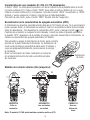
Nota: El modelo 61-765 mide también corriente continua (CC).
Característica de cero (modelos 61-765, 61-775 únicamente)
El botón “ZERO” se utiliza para la puesta a cero de la indicación de la pantalla antes de medir
corriente continua (CC). Pulse el botón “ZERO” para restar el número distinto de cero. Luego
mida la corriente continua (CC) en amperios. Al pulsar el botón “ZERO” nuevamente, el “ZERO”
destella, y vuelve a aparecer el número original que se había desplazado.
Para salir de este modo, pulse el botón “ZERO” durante más de 2 segundos.
Desactivación de la característica de apagado automático (APO)
El instrumento se desactiva automáticamente después de 30 minutos sin uso. Si en esa situación
pulsa cualquier botón, el instrumento se reactiva e indica en su pantalla la última lectura tomada
antes de desactivarse. Para desactivar la característica APO, pulse y retenga el botón ( / Hz)
mientras gira el selector a cualquier función deseada. Cuando se anula el apagado automático,
la leyenda “APO” desaparece de la pantalla. Al apagar y encender nuevamente el instrumento, se
restaura la característica de apagado automático por defecto.
Para encender y apagar la iluminación de fondo, pulse el botón
ubicado en la parte media del instrumento. La iluminación de
fondo verde permanece encendida durante unos 3 minutos y
luego se apaga automáticamente, para preservar la energía
de la batería.
Nota: La iluminación de fondo cuadruplica el consumo
de la batería.Iluminación de fondo encendida en todas
las funciones.
Medida de corriente alterna (CA) (amperios):
INCORRECTO
Las corrientes
se anulan
CORRECTO
Sólo un
conductor
CORRECTO
Uso con
divisor de
línea
H
N

19
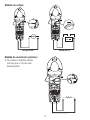
Medida de resistencia (ohmios):
• Para obtener medidas exactas,
verifique que el circuito esté
desenergizado.
Medida de voltaje:
Voltaje de CA Voltaje de CC

20
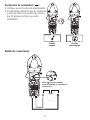
Verificación de continuidad ( ):
• Verifique que el circuito esté desenergizado.
• El instrumento detecta el nivel de resistencia
y emite un pitido si la resistencia es menor
que 30 Ω para confirmar que existe
continuidad.
Circuito
cerrado
Circuito
interrumpido
Medida de capacitancia
Pulse / Hz para conmutar
entre las medidas de capacitancia
y resistencia
La page est en cours de chargement...
La page est en cours de chargement...
La page est en cours de chargement...
La page est en cours de chargement...
La page est en cours de chargement...
La page est en cours de chargement...
La page est en cours de chargement...
La page est en cours de chargement...
La page est en cours de chargement...
La page est en cours de chargement...
La page est en cours de chargement...
La page est en cours de chargement...
La page est en cours de chargement...
La page est en cours de chargement...
La page est en cours de chargement...
La page est en cours de chargement...
-
 1
1
-
 2
2
-
 3
3
-
 4
4
-
 5
5
-
 6
6
-
 7
7
-
 8
8
-
 9
9
-
 10
10
-
 11
11
-
 12
12
-
 13
13
-
 14
14
-
 15
15
-
 16
16
-
 17
17
-
 18
18
-
 19
19
-
 20
20
-
 21
21
-
 22
22
-
 23
23
-
 24
24
-
 25
25
-
 26
26
-
 27
27
-
 28
28
-
 29
29
-
 30
30
-
 31
31
-
 32
32
-
 33
33
-
 34
34
-
 35
35
-
 36
36


Ideal 1000A AC/DC TRMS TightSight® Clamp Meter Mode d'emploi
- Catégorie
- Testeurs de réseau câblé
- Taper
- Mode d'emploi
- Ce manuel convient également à
dans d''autres langues
Documents connexes
Autres documents
-
VEVOR EM4659 Manuel utilisateur
-
DirekTronik DCM8500PV Le manuel du propriétaire
-
KPS DCM7000BT Le manuel du propriétaire
-
Amprobe ACD-3300 & ACD-3400 Industrial Clamp Meters Manuel utilisateur
-
Klein Tools CL450 Manuel utilisateur
-
Klein Tools MM700 Mode d'emploi
-
-
-
koban KPF-04 Le manuel du propriétaire
-
 Chauvin-Arnoux CA773 Manuel utilisateur
