Panasonic BT-H1700P Operating Instructions Manual
- Catégorie
- Téléviseurs
- Taper
- Operating Instructions Manual
Ce manuel convient également à

ENGLISH
Model BT-H1700P
Before attempting to connect, operate or adjust this product, please read thess instructions completly.
Operating
LCT1110-001A
1001-PN-I-U-VP
VOLUME
SLOT 1
A
B
DEGAUSS
MENU
SCREENS
CHECK
ASPECT
AREA
MARKER
UNDER
SCAN
PULSE
CROSS
COLOR
OFF
SLOT 2
C
D
SLOT 3
POWER
E
F
INPUT SELECT
Printed in Japan
VQT9586
Multi-Format Monitor
Instructions
P

SCREEN BURN
● It is not recommended to keep a certain still image
displayed on screen for a long time as well as displaying
extremely bright images on screen. This may cause a
burning (sticking) phenomenon on the screen of cathode-ray
tube. This problem does not occur as far as displaying
normal video playback motion images.
䡵 PRECAUTIONS
● Use only the power source specified on the unit.
(120 V/ AC, 60 Hz)
● Keep flammable material, water, and metal objects away
from the unit – especially the interior of the unit.
● This unit incorporates high voltage circuitry.
For your own safety and that of your equipment, do not
attempt to modify or disassemble this monitor.
There are no user-serviceable parts inside.
● Video or audio signals cannot be input to this monitor
without optional input cards.
● In these instructions, all explanations (except where noted)
refer to the BT-H1700P with input cards installed.
䡵 HANDLING
● Avoid shocks or vibrations. These may damage the unit and
cause it to malfunction.
● Do not block the ventilation slots.
● Do not expose this unit to high temperatures.
Extended exposure to direct sunlight or a heater could
deform the cabinet or cause the performance of internal
components to deteriorate.
● Do not place the unit near appliances generating strong
electric or magnetic fields. There can generate picture noise
and instability.
● Keep the monitor clean by wiping the cabinet and CRT
screen with a piece of soft cloth. Do not apply thinner or
benzine. These chemicals can damage the finish and erase
printed letters. When the unit is excessively dirty, use a
diluted neutral cleanser, then wipe away the cleanser with a
dry cloth.
DEGAUSS
● Do not use a magnet eraser to degauss the monitor’s
cathode ray tube from the outside. Doing so may distort its
aperture grill and cause a malfunction.
In order to prevent any fatal accidents caused by
misoperation or mishandling the monitor, be fully aware of all
the following precautions.
WARNINGS
To prevent fire or shock hazard, do not expose this
monitor to rain or moisture. Dangerous high voltages
are present inside the unit. Do not remove the back
cover of the cabinet. When servicing the monitor,
contrast qualified service personnel. Never try to
service it yourself.
WARNING : THIS APPARATUS
MUST BE EARTHED.
2
Improper operations, in particular alternation of high
voltage or changing the type of tube may result in x-ray
emission of considerable dose. A unit altered in such a
way no longer meets the standards of certification, and
must therefore no longer be operated.
This monitor is equipped with a 3-blade grounding-type
plug to satisfy FCC rule. If you are unable to insert the
plug into the outlet, contact your electrician.
FCC NOTICE (U.S.A. only)
CAUTION: Changes or modifications not approved by
PANASONIC could void the user’s authority to operate the
equipment.
NOTE: This equipment has been tested and found to
comply with the limits for a Class A digital device,
pursuant to Part 15 of the FCC Rules. These limits are
designed to provide reasonable protection against harmful
interference when the equipment is operated in a
commercial environment. This equipment generates,
uses, and can radiate radio frequency energy and, if not
installed and used in accordance with the instruction
manual, may cause harmful interference to radio
communications. Operation of this equipment in a
residential area is likely to cause harmful interference in
which case the user will be required to correct the
interference at his own expense.
SAFETY PRECAUTIONS

ENGLISH
3
SAFETY PRECAUTIONS ........................................................................2
CONTROLS AND FEATURES ................................................................4
CONTROLS AND FEATURES
(INPUT CARD: OPTIONAL) ....................................................................6
PREPARATION .......................................................................................8
BASIC MENU OPERATIONS
(MAIN MENU, SETUP MENU) ................................................................9
HOW TO USE “MAIN MENU”...............................................................10
HOW TO USE “SETUP MENU” ............................................................13
HOW TO USE EXTERNAL CONTROL ................................................. 17
TROUBLESHOOTING...........................................................................19
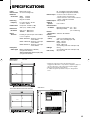
SPECIFICATIONS .................................................................................21
CONTENTS

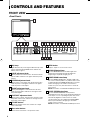
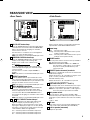
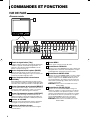
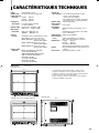
CONTROLS AND FEATURES
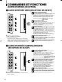
FRONT VIEW
<Front Panel>
Tally lamp
Lights when the tally control signal is ON. The tally control
signal is input through the MAKE remote terminal. For
details, refer to Page 17.
PHASE adjustment knob
Adjusts picture hue. Turn the knob to the left to make the
picture redder, and turn it to the right to make the picture
greener.
CHROMA adjustment knob
Adjusts picture colour density. Turn the knob to the left to
make the picture colour lighter, and turn it to the right to
make the picture colour deeper.
BRIGHT adjustment knob
Adjusts picture brightness. Turn the knob to the left to
make the picture darker, and turn it to the right to make
the picture brighter.
CONTRAST adjustment knob
Adjusts picture contrast. Turn the knob to the left to make
the picture contrast lower, and turn it to the right to make
the picture contrast higher.
VOLUME buttons
Adjusts the speaker volume. Also used to set or adjust
menu screen items.
Menu select buttons
Selects menu screen items or set-up menu screen.
1
8
2
3
4
5
6
7
9
VOLUME
SLOT 1
A
B
DEGAUSS
MENU
BLUE
CHECK
ASPECT
AREA
MARKER
UNDER
SCAN
PULSE
CROSS
COLOR
OFF
SLOT 2
C
D
SLOT 3
POWER
E
F
INPUT SELECT
VOLUME
SLOT 1
A
B
DEGAUSS
MENU
SCREENS
CHECK
ASPECT
AREA
MARKER
UNDER
SCAN
PULSE
CROSS
COLOR
OFF
SLOT 2
C
D
SLOT 3
POWER
E
F
INPUT SELECT
8
765432
1
9
10 11 12 16
13 14 15
17 18 19
20 21 22 23
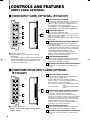
MENU button
Displays, adjusts or closes a menu screen.
DEGAUSS button/lamp
Press the DEGAUSS button. The button lights and
degaussing is performed automatically. When the
degaussing is completed, the light goes off.
UNDER SCAN button/lamp
Press the UNDER SCAN button. The button lights and
the screen is reduced (under-scan) and the whole screen
is displayed. When the UNDER SCAN button is pressed
while lit, the light goes off and the screen returns to
normal size (over-scan). Use this function to check the
whole screen.
NOTE: This function is invalid with the RGB-input screen.
PULSE CROSS button/lamp
Press the PULSE CROSS button. The picture is
separated into 4 parts. The synchronised signal displayed
in the shape of a cross separating the parts. The screen
automatically brightens to make it easier to confirm
synchronised sections easy. When the PULSE CROSS
button is pressed while lit, the light goes off and the
normal screen is restored.
NOTE: This function is invalid with the RGB-input screen.
10
11
4

ENGLISH
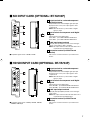
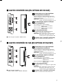
REAR/SIDE VIEW
<Rear Panel>
COLOR OFF button/lamp
Press the COLOR OFF button. The button lights and the
screen becomes monochrome. When the COLOR OFF
button is pressed while lit, the light goes off and the
normal screen is restored.
Use this function to confirm the noise in the brightness
signal or to confirm the white balance.
NOTE: This function is invalid with the RGB-input screen.
SCREENS CHECK button/lamp
Press the SCREENS CHECK button. The button lights
and the screen changes in the following order:
Normal screen[Red screen[Green screen
Blue screenp
Press the SCREENS CHECK button when the blue
screen is displayed. The light goes off and the normal
screen is restored.
Use this function to confirm or adjust CHROMA or
PHASE.
NOTE: This function is invalid with the RGB-input screen.
ASPECT button/lamp
When the ASPECT button is pressed while the screen
ratio is 4:3, the button lights and the screen ratio changes
to 16:9. When the ASPECT button is pressed while lit, the
light goes off and the normal screen is restored.
NOTE: This function is invalid with the RGB-input screen.
AREA MARKER button/lamp
When the AREA MARKER button is pressed while the
screen ratio is 16:9, the button lights and the white
marker is displayed. This shows the screen size (area)
set on the menu. When the AREA MARKER button is
pressed while lit, the light goes off and the normal screen
is restored.
NOTE: This function is invalid with the RGB-input screen.
– INPUT SELECT buttons/lamps
Press the unlit button. The button lights and the input
signal is changed. (any other lit button goes off.)
When the lit button is pressed, the status of the current
input signal is displayed (for approx. 3 seconds). Buttons
A through F correspond to the signals input via the input
cards installed in SLOT 1 through SLOT 3.
A, B : select the picture from the SLOT 1 input card.
C, D : select the picture from the SLOT 2 input card.
E, F : select the picture from the SLOT 3 input card.
12
MAKE
SLOT1
RS-232C
REMOTE
SLOT2
SLOT3
MAIN POWER
24
25
26
27
28
<Side Panel>
Refer to pages 8 and 9 for correspondence between the
input terminals and the INPUT SELECT buttons.
Power lamp
Unlit : The main power is OFF.
Orange : The main power is ON, but the monitor’s power
is OFF (in stand-by mode).
Green : The main power is ON, and the monitor’s power
is ON (in normal operation mode).
POWER switch
Press the power switch to turn the monitor’s power ON or
OFF when the main power is ON.
NOTE: When RUSH DELAY TIME is set to MODE 2 in
the set-up menu, it takes approx. 3.2 seconds for
the power to actually turn ON after the power
switch is pressed.
REMOTE (external control) terminals
Terminals for controlling the monitor from an external unit.
MAKE terminal (Upper):
Enables the monitor to be controlled by closing the circuit
(point of contact) connected to the terminal.
RS-232C terminal (Lower):
Enables the monitor to be controlled from a personal
computer via serial communication.
Input card slots (SLOT 1 — SLOT 3)
Optional input cards can be installed in these slots. Input
cards are not provided when you purchase the monitor.
NOTE: It is not possible to input video or audio signals to
the monitor when no input cards are installed.
Main power switch
Press the switch to turn the main power ON or OFF.
When the main power is ON, the power lamp on the front
panel lights in yellow and the monitor enters the stand-by
mode.
I : ON 䡬 : OFF
AC inlet
Power input connector. Connect the provided AC power
cord to an AC outlet (120 V/230 V AC, 50 Hz/60 Hz).
Built-in speaker (monaural)
Outputs the input audio.
13
14
15
16
21
22
23
24
25
26
27
28
[
5

Video input/output terminals
Input (IN) and output (OUT) terminals for component
(colour deference) or RGB signals.
The IN and OUT terminals are bridge-connected.
(When no cable is connected to the OUT terminal, the
input signal is automatically terminated.)
Select component signal : press INPUT SELECT A/C/E
button
Select RGB signal : press INPUT SELECT B/D/F
button
Synchronised signal input/output terminals
Input (IN) and output (OUT) terminals for the vertical,
horizontal or complex synchronised signals.
The synchronised signals from these terminals have
priority over other terminals. When no synchronised signal
is input to these terminals, the synchronised signal from
the video input/output terminals (G/Y terminals) is valid.
The IN and OUT terminals are bridge-connected.
(When no cable is connected to the OUT terminal, the
input signal is automatically terminated.)
Audio input/output terminals
Input (IN) and output (OUT) terminals for audio signals.
The IN and OUT terminals are bridge-connected.
Connection terminal (to a Multi-Format Monitor)
Attach to the connection terminal of your multi-format
monitor.
1
CONTROLS AND FEATURES
(INPUT CARD: OPTIONAL)
䡵 COMPONENT/RGB INPUT CARD (OPTIONAL:
BT-YA702P)
䡵 Compatible signal formats:
NTSC (3.58 MHz), PAL (4.43 MHz), black-and-white
(50 Hz/60 Hz)
* You can select “AUTO” (automatic selection), “NTSC” or
“PAL” in SETUP MENU when switching NTSC or PAL.
Normally select AUTO. However, if the input signal is
unstable, select NTSC or PAL.
B/P
B
/B-Y
G/Y
OUTIN
OUTIN
R/P
R
/B-Y
OUTIN
VD
OUTIN
HD/C
S
OUTIN
OUTIN
AUDIO
OUT
IN
1
2
3
4
䡵 VIDEO INPUT CARD (OPTIONAL: BT-YA701P)
VIDEO 1
OUT
IN
AUDIO 2
AUDIO 1
OUT
IN
VIDEO 2
OUT
Y/C IN
IN
OUT
IN
EXT.SYNC
1
2
3
4
5
䡵 Compatible signal formats:
480/60i, 576/50i, 576/50p, 480/60p, 720/60p, 1035/60i,
1080/50i, 1080/60i
Video input/output terminals
Input (IN) and output (OUT) terminals for video signals.
The IN and OUT terminals are bridge-connected.
(When no cable is connected to the OUT terminal, the
input signal is automatically terminated.)
Select VIDEO 1 : press INPUT SELECT A/C/E button
Select VIDEO 2 : press INPUT SELECT B/D/F button
S-video input terminal
Input terminal for the S-video signal.
When an S-video signal is input to this terminal and a
video signal is input to VIDEO 2, the S-video signal has
priority over the video signal.
When choosing the S-video input, press INPUT SELECT
B/D/F button.
Synchronised signal input/output terminals
Input (IN) and output (OUT) terminals for the complex
synchronised signals.
The synchronised signals from these terminals have priority
over signals from other terminals. When no synchronised
signal is input to these terminals, the synchronised signal
from the video input/output terminals is valid.
The IN and OUT terminals are bridge-connected.
(When no cable is connected to the OUT terminal, the
input signal is automatically terminated.)
Audio input/output terminals
Input (IN) and output (OUT) terminals for audio signals
corresponding to VIDEO 1 and VIDEO 2. The IN and
OUT terminals are bridge-connected.
Connection terminal (to a Multi-Format Monitor)
Attach to the connection terminal of your multi-format
monitor.
1
2
3
4
2
3
4
5
6

ENGLISH
䡵 SDI INPUT CARD (OPTIONAL: BT-YA703P)
AUDIO 2
AUDIO 1
OUT
IN
SWITCHED
OUT
SDI 1
SDI 2
IN
IN
1
2
3
4
Output terminal for a selected component
serial digital signal
Output terminal for s selected digital signal (the input
displayed on the screen). The output signal is cable-
compensated.
NOTE: When the monitor’s power is OFF, no digital
signal is output.
Input terminals for component serial digital
signals
Input terminals for the digital signal.
Select SDI 1 : press INPUT SELECT A/C/E button
Select SDI 2 : press INPUT SELECT B/D/F button
Audio input/output terminals
Input (IN) and output (OUT) terminals for the analogue
signals corresponding to SDI 1 and SDI 2.
NOTE: This input card cannot decode audio data even if
contained in the input digital signal.
Connection terminal (to a Multi-Format
Monitor)
Attach to the connection terminal of your multi-format
monitor.
1
䡵 Compatible signal formats: 480/60i, 576/50i
2
3
4
䡵 HD SDI INPUT CARD (OPTIONAL: BT-YA704P)
䡵 Compatible signal formats: 720/60p, 1035/60i, 1080/50i,
1080/60i, 1080/24psF
Output terminal for a selected component
serial digital signal
Output terminal for s selected digital signal (the input
displayed on the screen). The output signal is cable-
compensated.
NOTE: When the monitor’s power is OFF, no digital
signal is output.
Input terminals for component serial digital
signals
Input terminals for the digital signal.
Select HD SDI 1 : press INPUT SELECT A/C/E button
Select HD SDI 2 : press INPUT SELECT B/D/F button
Audio input/output terminals
Input (IN) and output (OUT) terminals for the analogue
audio signals.
NOTE: This input card cannot decode audio data even if
contained in the input digital signal.
Connection terminal (to a Multi-Format
Monitor)
Attach to the connection terminal of your multi-format
monitor.
1
2
3
4
AUDIO
OUT
IN
SWITCHED
OUT
HD SDI 1
HD SDI 2
IN
IN
1
2
3
4
7

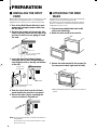
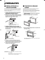
PREPARATION
1. Turn off the Multi-Format Monitor’s main
power and unplug the power cable from
the AC outlet.
2. Unscrew the screws and remove the slot
cover from the slot (on the rear side of the
monitor) in which you are going to install
the card.
3. Insert the Input Card’s board (green-
coloured) into the slot, fitting the board
into the guide rails on the top and bottom
of the slot.
4. Push the Input Card in so that its front
panel touches the monitor’s rear panel.
5. Secure the Input Card by replacing the
screws removed in Procedure 2.
䡵 INSTALLING THE INPUT
CARD
Optional input cards are necessary to use the functions of this
monitor. Before mounting the monitor or connecting other
equipment to the monitor, be sure to install the input cards.
䡵 ATTACHING THE WIDE
MASK
A wide mask is provided with the monitor. This changes the
viewable screen area to the 16:9 aspect ratio.
The wide mask cannot be attached to the monitor after the
monitor is mounted in a rack. Mount the wide mask before
installing the monitor in a rack.
1. Prepare the provided wide mask and 4
screws (for attaching).
2. Attach the wide mask to the monitor.
3. Secure the wide mask with the screws (fix
2 screws each to both right and left side).
● When detaching the wide mask, follow this procedure in
reverse.
Slot cover
Fit the board to
the guide rails.
Rear side of the BT-H1700P
multi-format monitor
Knob
Input card (the illustration shown
is of the BT-YA701P)
Guide rails
Knob
NOTE :Do not touch the terminal connected to the monitor or
board pattern.
Do not remove slot covers from the monitor’s slots if
they are not in use.
8

ENGLISH
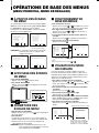
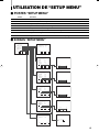
BASIC MENU OPERATIONS
(MAIN MENU, SETUP MENU)
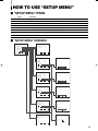
䡵 ABOUT MENU SCREENS
This monitor features a MAIN MENU (main menu screen) and
a SETUP MENU (setup menu screen).
The MAIN MENU contains the functions normally used, and
the SETUP MENU contains the settings required for initial
setup.
<SETUP MENU>
FUNCTION SETTING
PICTURE SUB ADJ.
COLOR TEMP/BAL.
SIZE/POSI.ADJ.
DISTORTION ADJ.
STATUS DISPLAY
CONTROL LOCK :ON
all reset
EXIT:
MENU
ENTER:+ SELECT:
<MAIN MENU>
APERTURE CONTROL
SLOT CONDITION
sub menu POSITION :LOWER
AREA MAKER :OFF
AREA MAKER-R :OFF
CENTER MAKER :OFF
COLOR MATRIX
EXIT:
MENU
ENTER:+ SELECT:
<MAIN MENU>
APERTURE CONTROL
SLOT CONDITION
sub menu POSITION :LOWER
COLOR MATRIX
EXIT:
MENU
ENTER:+ SELECT:
<MAIN MENU>
SLOT CONDITION
sub menu POSITION :LOWER
EXIT:
MENU
ENTER:+ SELECT:
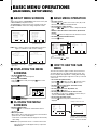
䡵 DISPLAYING THE MENU
SCREENS
● To display MAIN MENU
Press the
MENU
button on the front panel.
●To display SETUP MENU
Press the button while pressing the button on the
front panel.
VOLUME
SLOT 1
A
B
DEGAUSS
MENU
BLUE
CHECK
ASPECT
AREA
MARKER
UNDER
SCAN
PULSE
CROSS
COLOR
OFF
SLOT 2
C
D
SLOT 3
POWER
E
F
INPUT SELECT
VOLUME
DEGAUSS
MENU
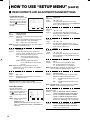
䡵 CLOSING THE MENU
SCREENS
● Using the MENU button
Press the
MENU
button a few times until the Menu Screen
disappears.
● With no operation
When approx. 30 seconds have passed since the last Menu
operation, both screens will disappear.
* Some items on the Menu Screens disappear automatically
after setting.
NOTE:When you perform the “reset” or “all reset” function, the
Menu Screen does not disappear unless you press the
MENU button.
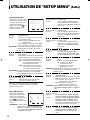
䡵 BASIC MENU OPERATION
● To select an item,
Press the or buttons to move the cursor (
4
) on the
Menu Screens and select the desired item.
● To set (select) or adjust an item,
Press the
or buttons to select or adjust the desired
item.
● When the desired item has other menus (hierarchical
menus),
Press the button to display the lower hierarchical menu.
● To return to the former Menu Screen,
Press the
MENU
button.
<MAIN MENU>
APERTURE CONTROL
SLOT CONDITION
sub menu POSITION :LOWER
AREA MAKER :OFF
AREA MAKER-R :OFF
CENTER MAKER :OFF
COLOR MATRIX
EXIT:
MENU
ENTER:+ SELECT:
<APERTURE CONTROL>
LEVEL :00
CONTROL FREQ. :HIGH
sub menu
reset
EXIT:
MENU
ENTER:+ SELECT:
MENU
䡵 HOW TO USE THE SUB
MENU
The sub menu function applies to Menu Screen items that
should be adjusted or set while watching the picture. This
function simplifies the adjustment or setting while watching
the picture by displaying the single item on the top or bottom
of the screen.
● To use the sub menu function,
Press the
or buttons to select “ sub menu”. Then,
press the
button to display the sub menu screen.
● To adjust or set an item in the sub menu screen,
Press the or buttons.
● To change the item to be adjusted or set,
Press the
or buttons.
● To change the position of the sub menu screen,
Set “UPPER” (on the top) or “LOWER” (on the bottom) in
“sub menu POSITION” of MAIN MENU.
● To close the sub menu screen,
Press the
MENU
button. The previous Menu Screen is
displayed.
<PICTURE SUB ADJ.>
CONTRAST :00
BRIGHT :00
CHROMA :00
PHASE :00
NTSC SETUP :00
COMPO.LEVEL :SMPTE
sub menu
reset
EXIT:
MENU
ENTER:+ SELECT:
CONTRAST : 00
- - + +
CONTRAST : 00
- - + +
MAIN MENU (main menu screen)
SETUP MENU
(setup menu screen)
The upper pale screen; when setting
“UPPER” in “sub menu POSITION”
The lower dark screen; when setting
“LOWER” in “sub menu POSITION”
MAIN MENU when the 4:3 video
signal is input
NOTE : The contents of menus vary depending on the input
signal or combination of the monitor’s settings.
MAIN MENU when the RGB signal
is input
Cursor
Move (select) with the
or buttons.
Press the
or buttons to
select or adjust the item.
Menu in an item
Example of sub menu screen
9

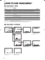
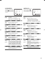
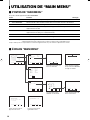
HOW TO USE “MAIN MENU”
䡵 “MAIN MENU” ITEMS
The following items appear in MAIN MENU.
Items
Functions Displays
1 APERTURE CONTROL Compensates the frequency characteristics of the input video signal. *1
2 SLOT CONDITION Displays the status of the input cards installed in each of the input card slots.
3 sub menu POSITION Selects the display position of the sub menu superimposed on the screen.
4 AREA MARKER Selects the size marker for the other screen ratio used when the screen
ratio is 16:9.
*2
5 AREA MARKER-R Selects the size marker for the other screen ratio used when the screen ratio is
16:9. (for external control)
*2
6 CENTER MARKER Makes the centre marker appear or disappear. *2
7 COLOR MATRIX Selects or adjusts the picture colour matrix. *1
䡵 “MAIN MENU” SCREENS
<MAIN MENU>
APERTURE CONTROL
SLOT CONDITION
sub menu POSITION :LOWER
AREA MAKER :OFF
AREA MAKER-R :OFF
CENTER MAKER :OFF
COLOR MATRIX
EXIT:
MENU
ENTER:+ SELECT:
<MAIN MENU>
APERTURE CONTROL
SLOT CONDITION
sub menu POSITION :LOWER
COLOR MATRIX
EXIT:
MENU
ENTER:+ SELECT:
<MAIN MENU>
SLOT CONDITION
sub menu POSITION :LOWER
EXIT:
MENU
ENTER:+ SELECT:
<APERTURE CONTROL>
LEVEL :00
CONTROL FREQ. :HIGH
sub menu
reset
EXIT:
MENU
ADJUST:- + SELECT:
<SLOT CONDITION>
INPUT A : VIDEO-1
INPUT B : VIDEO-2
INPUT C : COMPO.
INPUT D : RGB
INPUT E : NO SLOT
INPUT F : NO SLOT
EXIT:
MENU
<COLOR MATRIX>
SELECT :ITU601
EXIT:
MENU
ADJUST:- + SELECT:
LEVEL :+05
- - + +
LEVEL :+05
- - + +
R-Y PHASE :+90
- - + +
<COLOR MATRIX>
SELECT :MANUAL
R-Y PHASE :90
R/B GAIN :0.86
G-Y PHASE :138
G/B GAIN :0.36
sub menu
reset
EXIT:
MENU
ADJUST:- + SELECT:
The menu screen when “sub
menu” is selected.
About “Displays” *1: Not displayed when an RGB signal is input.
*2: Displayed only when the screen ratio is 16:9. Not displayed when an RGB signal is input.
When some items are not displayed depending on the input signals, subsequent items will move up.
The sub menu screen when
“sub menu POSITION” is set
to “UPPER”.
The menu screen when
“MANUAL” is selected.
The menu screen when “sub
menu” is selected.
The menu screen when the
screen ratio is 4:3
The menu screen when an
RGB signal is input
10

ENGLISH
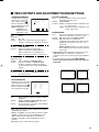
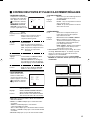
1. APERTURE CONTROL
Compensates the frequency
characteristics of the input
video signal. Press the
button to display the setting
menu illustrated on the right.
NOTE :APERTURE
CONTROL is not
displayed when the
RGB signal is input.
● INPUT A/B corresponds to SLOT 1, INPUT C/D to SLOT 2,
and INPUT E/F to SLOT 3.
● VIDEO-1 or VIDEO-2 shows the video input card is installed.
COMPO. or RGB shows the component/RGB input card.
SDI 1 or SDI 2 shows the SDI input card is installed.
HD SDI 1 or HD SDI 2 shows the HD SDI input card is
installed.
● NO SLOT shows no input cards are installed.
Item : LEVEL
Adjustment
range : 00 ~ +10
Function : Adjusts the compensate value. The higher the
number is, the larger the compensate value gets.
Item : CONTROL FREQ.
Settings : HIGH/LOW/OFF
Function : Adjusts the frequency compensation.
HIGH : Compensates the high frequencies.
LOW : Compensates the low frequencies.
OFF : Deactivates the aperture compensation.
Item : sub menu
Adjustment range/
Settings : Same as LEVEL or CONTROL FREQ.
Function : Performs the LEVEL or CONTROL FREQ.
settings in a single-line display. The display
position depends on the “sub menu POSITION”
setting.
Item : reset
Function : Sets the LEVEL and CONTROL FREQ. values to
factory-preset ones.
2. SLOT CONDITION
Displays the status of the input
cards installed in each of the
input card slots. Press the
button to display the setting
menu illustrated on the right.
<SLOT CONDITION>
INPUT A : VIDEO-1
INPUT B : VIDEO-2
INPUT C : COMPO.
INPUT D : RGB
INPUT E : NO SLOT
INPUT F : NO SLOT
EXIT:
MENU
䡵 ITEM CONTENTS AND ADJUSTMENT RANGE/SETTINGS
16:9
4:3
14:9 13:9
<APERTURE CONTROL>
LEVEL :00
CONTROL FREQ. :HIGH
sub menu
reset
EXIT:
MENU ADJUST:- + SELECT:
Items : INPUT A:/INPUT B:/INPUT C:/INPUT D:/INPUT
E:/INPUT F:
Settings : VIDEO-1/VIDEO-2/COMPO./RGB/SDI 1/SDI 2/
HD SDI 1/HD SDI 2/NO SLOT
Function : Displays the status of the input cards installed in
each of the input card slots.
3. sub menu POSITION
Items : Selects the display position of the sub menu
superimposed on the screen.
Settings : UPPER/LOWER
Functions : UPPER : An adjustment item is displayed on the
top of the screen.
LOWER : An adjustment item is displayed on the
bottom of the screen.
4. AREA MARKER
Items : Selects the size marker for the other screen ratio
(aspect) used when the screen ratio is 16:9.
Settings : OFF/16:9/4:3/13:9/14:9/MODE 1/MODE 2
Functions : OFF: The marker is not displayed.
16:9/4:3/13:9/14:9: Displays the marker (a white
quadrangle) showing the screen size of each
aspect ratio.
MODE 1/MODE 2: Displays no markers because
these settings will be used for function expansion
in the future.
● AREA MARKER is displayed when a 16:9 picture such as
1080i/1035i/720p etc. is displayed or the picture is
switched to the 16:9 screen ratio by pressing the ASPECT
button.
● To actually display the marker, the AREA MARKER
button on the monitor needs to be pressed so that it is
illuminated.
11

Input Signal Format Standard Manual
setting setting
(MANUAL)
NTSC, PAL, 480/60i,
ITU601
480/60p, 576/50i, 575/50p
ITU709
720/60p, 1080/50i, 1080/60i,
ITU709
1035/60i, 1080/24psF
<COLOR MATRIX>
SELECT :MANUAL
R-Y PHASE :90
R/B GAIN :0.86
G-Y PHASE :244
G/B GAIN :0.30
sub menu
reset
EXIT:
MENU
ADJUST:- + SELECT:
5. AREA MARKER-R
Items : Selects the size marker for the other screen ratio
(aspect) used when the screen ratio is 16:9. (for
external control)
Settings : OFF/16:9/4:3/13:9/14:9/MODE 1/MODE 2
Functions : OFF: The marker is not displayed.
16:9/4:3/13:9/14:9: Displays the marker (a white
quadrangle) showing the screen size of each
aspect ratio.
MODE 1/MODE 2: Displays no markers because
these settings will be used for function expansion
in the future.
●AREA MARKER-R is displayed when a 16:9 picture such
as 1080i/1035i/720p etc. is displayed or the picture is
switched to the 16:9 screen ratio by pressing the ASPECT
button.
●The marker is actually displayed when the external control
selects each setting. (No markers are displayed even if
each marker is selected only in the monitor’s AREA
MARKER-R setting.)
6. CENTER MARKER
Items : Makes the centre marker appear or disappear.
Settings : ON/OFF
Functions : ON : The centre marker (a white cross) is
displayed on the centre of the screen.
OFF : The marker disappears.
●To actually display the marker, the AREA MARKER
button on the monitor needs to be pressed so that it is
illuminated.
Centre marker
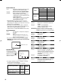
7. COLOR MATRIX
Selects or adjusts the
standard of the colour
demodulation (colour
rendering). Press the
button to display the setting
menu illustrated on the right.
The menu screen when
MANUAL is selected.
● The standard setting is set to “ITU601” or “ITU709”
depending on the input signal format.
The factory preset of MANUAL is ITU709
Item : SELECT
Function : Selects the picture matrix standard.
Settings : ITU601 or ITU709/ MANUAL
ITU601 or ITU709 : Standard setting
MANUAL : Manual setting
NOTE :The following items are displayed when MANUAL is
selected. When ITU601 or ITU709 is selected, they
are not displayed.
Item : R-Y PHASE
Function : Sets the R-Y phase.
Settings : 90/92/94/112
Item : R/B GAIN
Function : Sets the R/B gain.
Settings : 0.86/0.56/0.68/0.79
Item : G-Y PHASE
Function : Sets the G-Y phase.
Settings : 244/253/236/240
Item : G/B GAIN
Function : Sets the G/B gain.
Settings : 0.30/0.34/0.40/0.45
Item : sub menu
Function : Performs the R-Y PHASE, R/B GAIN, G-Y
PHASE or G/B GAIN settings in a single-line
display. The display position depends on the
“sub menu POSITION” setting.
Settings : Same as R-Y PHASE, R/B GAIN, G-Y PHASE or
G/B GAIN
Item : reset
Function : Sets the R-Y PHASE, R/B GAIN, G-Y PHASE
and G/B GAIN values to factory-preset ones.
R-Y PHASE 90
ITU601
R/B GAIN 0.79
G-Y PHASE 244
G/B GAIN 0.45
R-Y PHASE 90
ITU709
R/B GAIN 0.86
G-Y PHASE 244
G/B GAIN 0.30
12

ENGLISH
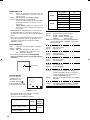
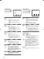
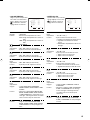
HOW TO USE “SETUP MENU”
䡵 “SETUP MENU” ITEMS
Items Functions
1 FUNCTION SETTING Displays the monitor’s power-up time or the total usage time.
2 PICTURE SUB ADJ. Performs approximate adjustments using the control knobs on the front panel.
3 COLOR TEMP./BAL. Sets or adjusts the colour temperature or white balance.
4 SIZE/POSI. ADJ. Adjusts the size or position of the picture.
5 DISTORTION ADJ. Compensates the picture distortion.
6 STATUS DISPLAY Makes the status of the input signal appear or disappear on the screen.
7 CONTROL LOCK Sets the control lock preventing the monitor from misuse.
8 all reset Sets all items in SETUP MENU to factory-preset values.
䡵 “SETUP MENU” SCREENS
<SETUP MENU>
FUNCTION SETTING
PICTURE SUB ADJ.
COLOR TEMP./BAL.
SIZE/POSI.ADJ.
DISTORTION ADJ.
STATUS DISPLAY
CONTROL LOCK :ON
all reset
EXIT:
MENU
ENTER:+ SELECT:
<FUNCTION SETTING>
COLOR SYSTEM :AUTO
RUSH DELAY TIME :STD.
HOUR METER X100h :000
EXIT:
MENU
ADJUST:- + SELECT:
<PICTURE SUB ADJ.>
CONTRAST :00
BRIGHT :00
CHROMA :00
PHASE :00
NTSC SETUP :00
COMPO.LEVEL :SMPTE
sub menu
reset
EXIT:
MENU
ADJUST:- + SELECT:
<COLOR TEMP./BAL.>
COLOR TEMP. :LOW
BLUE DRIVE :000
RED DRIVE :000
GREEN CUTOFF :000
BLUE CUTOFF :000
RED CUTOFF :000
sub menu
reset
EXIT:
MENU
ADJUST:- + SELECT:
<SIZE/POSI. ADJ.>
H.SIZE :00
H.POSITION :00
V.SIZE :00
V.POSITION :00
sub menu
reset
EXIT:
MENU
ADJUST:- + SELECT:
<DISTORTION ADJ.>
PINCUSHION :00
PIN.BALANCE :00
PARALLELOGRAM :00
TRAPEZOID :00
sub menu
reset
EXIT:
MENU
ADJUST:- + SELECT:
<STATUS DISPLAY>
STATUS DISPLAY :ON
1080/1035 :1080
EXIT:
MENU
ADJUST:- + SELECT:
CONTRAST : 00
- - + +
BLUE DRIVE :000
- - + +
H.SIZE : 00
- - + +
PINCUSHION : 00
- - + +
Aer you sure ?
"Yes" then + Key.
"No" then
MENU
Key.
13

HOW TO USE “SETUP MENU” (cont'd)
<FUNCTION SETTING>
COLOR SYSTEM :AUTO
RUSH DELAY TIME :STD.
HOUR METER X100h :000
EXIT:
MENU
ADJUST:- + SELECT:
<PICTURE SUB ADJ.>
CONTRAST :00
BRIGHT :00
CHROMA :00
PHASE :00
NTSC SETUP :00
COMPO.LEVEL :SMPTE
sub menu
reset
EXIT:
MENU
ADJUST:- + SELECT:
䡵 ITEM CONTENTS AND ADJUSTMENT RANGE/SETTINGS
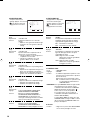
1. FUNCTION SETTING
Selects the colour system and
displays the monitor’s power-
up time or the total usage time.
Press the
button to display
the setting menu illustrated on
the right.
Item : COLOR SYSTEM
Settings : AUTO/NTSC/PAL
Function : Selects the colour system when using the video
input card.
AUTO : Change NTSC and PAL automatically.
NTSC : Keeps the colour system NTSC.
PAL : Keeps the colour system PAL.
NOTE :Normally select AUTO. However, if the input signal is
unstable, select NTSC or PAL.
Item : RUSH DELAY TIME
Settings : STD./SLOW
Function : Sets the time when the power supply to the
monitor’s circuits (excluding the micro computers)
starts after the power switch is pressed.
STD. : The power supply starts approx.
1 second after the power switch is
pressed.
SLOW : The power supply starts approx.
3.2 seconds after the power switch is
pressed.
NOTE :When turning on many multi-format monitors
simultaneously, it is recommended to use SLOW to
control rush current.
Item : HOUR METER X100h
Number
range : 000 ~ 655
Function : Displays the total usage time of the monitor in
hundred-hour units.
● When the timer passes 655, it returns to 000.
● The timer does not count the usage time under one hour.
2. PICTURE SUB ADJ.
Performs approximate
adjustments using the control
knobs on the front panel. Press
the
button to display the
setting menu illustrated on the
right.
NOTE : When the RGB signal
is input, only
CONTRAST and
BRIGHT are displayed. When the PAL signal is
input, only CONTRAST, BRIGHT and CHROMA are
displayed.
Item : CONTRAST
Adjustment
range : –20 ~ 00 ~ +20
Function : For approximate adjustment of the picture
contrast. Before adjustment, set the CONTRAST
knob on the front panel to 0.
Item : BRIGHT
Adjustment
range : –20 ~ 00 ~ +20
Function : For approximate adjustment of the picture
brightness. Before adjustment, set the BRIGHT
knob on the front panel to 0.
Item : CHROMA
Adjustment
range : –20 ~ 00 ~ +20
Function : For approximate adjustment of the colour
density. Before adjustment, set the CHROMA
knob on the front panel to 0.
Item : PHASE
Adjustment
range : –20 ~ 00 ~ +20
Function : For approximate adjustment of the picture hue.
Before adjustment, set the PHASE knob on the
front panel to 0.
Item : NTSC SETUP
Settings : 00/7.5
Function : Sets the level of the input NTSC signal.
00 : Compliant with 0% set-up signal.
7.5 : Compliant with 7.5% set-up signal.
NOTE : NTSC SETUP is displayed only when the video input
card is installed and an NTSC signal is input.
Item : COMPO. LEVEL
Settings : SMPTE/B75/B00
Function : Sets the level of the input component signal.
SMPTE : Compliant with M2VTR signals.
B75 : Compliant with Betacam 7.5% set-up
signal.
B00 : Compliant with Betacam 0% set-up
signal.
NOTE : COMPO. LEVEL is displayed only when a 480/60i,
480/60p, 576/50i or 576/50p signal is input.
Item : sub menu
Adjustment range/
Settings : Same as CONTRAST, BRIGHT, CHROMA,
PHASE and COMPO. LEVEL/NTSC SETUP.
Function : Performs CONTRAST, BRIGHT, CHROMA,
PHASE or COMPO. LEVEL/NTSC SETUP
settings in a single-line display. The sub menu
display varies depending on the selected item.
Item : reset
Function : Sets the CONTRAST, BRIGHT, CHROMA,
PHASE and COMPO. LEVEL/NTSC SETUP
values to factory-preset ones.
14

ENGLISH
<COLOR TEMP./BAL.>
COLOR TEMP. :LOW
BLUE DRIVE :000
RED DRIVE :000
GREEN CUTOFF :000
BLUE CUTOFF :000
RED CUTOFF :000
sub menu
reset
EXIT:
MENU
ADJUST:- + SELECT:
<SIZE/POSI. ADJ.>
H.SIZE :00
H.POSITION :00
V.SIZE :00
V.POSITION :00
sub menu
reset
EXIT:
MENU
ADJUST:- + SELECT:
3. COLOR TEMP./BAL.
Sets or adjusts the colour
temperature or white balance.
Press the
button to display
the setting menu illustrated on
the right.
Item : COLOR TEMP.
Settings : HIGH/LOW
Function : Selects the colour temperature.
HIGH : Sets the colour temperature to D93.
LOW : Sets the colour temperature to D65™.
Item : BLUE DRIVE
Adjustment
range : MIN ~ 000 ~ MAX (in 127 grades)
Function : Adjusts the blue drive level.
Item : RED DRIVE
Adjustment
range : MIN ~ 000 ~ MAX (in 127 grades)
Function : Adjusts the red drive level.
Item : GREEN CUTOFF
Adjustment
range : MIN ~ 000 ~ MAX (in 255 grades)
Function : Sets the green cut-off point.
Item : BLUE CUTOFF
Adjustment
range : MIN ~ 000 ~ MAX (in 255 grades)
Function : Sets the blue cut-off point.
Item : RED CUTOFF
Adjustment
range : MIN ~ 000 ~ MAX (in 255 grades)
Function : Sets the red cut-off point.
Item : sub menu
Adjustment range/
Settings : Same as BLUE DRIVE, RED DRIVE, GREEN
CUTOFF, BLUE CUTOFF and RED CUTOFF.
Function : Performs BLUE DRIVE, RED DRIVE, GREEN
CUTOFF, BLUE CUTOFF or RED CUTOFF
settings in a single-line display. The sub menu
display varies depending on the selected item.
Item : reset
Function : Sets the BLUE DRIVE, RED DRIVE, GREEN
CUTOFF, BLUE CUTOFF and RED CUTOFF
values to factory-preset ones.
4. SIZE/POSI. ADJ.
Adjusts the size or position of
the picture. Press the
button to display the setting
menu illustrated on the right.
Item : H.SIZE
Adjustment
range : –20 ~ 00 ~ +20 ( * )
Function : Adjusts the horzitontal screen size.
– : Reduces the screen size horizontally.
+ : Enlarges the screen size horizontally.
* : Reduced to 00 ~ +20 during the under-scan mode.
Item : H.POSITION
Adjustment
range : –20 ~ 00 ~ +20
Function : Adjusts the horzitontal screen position.
– : Move the screen to the left.
+ : Move the screen to the right.
Item : V.SIZE
Adjustment
range : –20 ~ 00 ~ +20
Function : Adjusts the vertical screen size.
– : Reduces the screen size vertically.
+ : Enlarges the screen size vertically.
Item : V.POSITION
Adjustment
range : –20 ~ 00 ~ +20
Function : Adjusts the vertical screen position.
– : Move the screen up.
+ : Move the screen down.
Item : sub menu
Adjustment range/
Settings : Same as H.SIZE, H.POSITION, V.SIZE and
V.POSITION.
Function : Performs H.SIZE, H.POSITION, V.SIZE or
V.POSITION settings in a single-line display. The
sub menu display varies depending on the
selected item.
Item : reset
Function : Sets the H.SIZE, H.POSITION, V.SIZE and
V.POSITION values to factory-preset ones.
15

<STATUS DISPLAY>
STATUS DISPLAY :ON
1080/1035 :1080
EXIT:
MENU
ADJUST:- + SELECT:
<DISTORTION ADJ.>
PINCUSHION :00
PIN.BALANCE :00
PARALLELOGRAM :00
TRAPEZOID :00
sub menu
reset
EXIT:
MENU
ADJUST:- + SELECT:
5. DISTORTION ADJ.
Compensates the picture
distortion. Press the
button
to display the setting menu
illustrated on the right.
Item : PINCUSHION
Adjustment
range : –20 ~ 00 ~ +20
Function : Compensates pincushion picture distortion.
– : Expands both left and right sides of the
picture.
+ : Squeezes both left and right sides of the
picture.
Item : PIN.BALANCE
Adjustment
range : –20 ~ 00 ~ +20
Function : Adjusts the compensation balance of the
pincushion picture distortion.
– : The picture is expanded on the left side, and
squeezed on the right side.
+ : The picture is squeezed on the left side, and
expanded on the right side.
Item : PARALLELOGRAM
Adjustment
range : –20 ~ 00 ~ +20
Function : Compensates parallelogram picture
distortion.
– : Moves the upper side of the picture to the
right, and the lower side to the left.
+ : Moves the upper side of the picture to the left,
and the lower side to the right.
Item : TRAPEZOID
Adjustment
range : –20 ~ 00 ~ +20
Function : Compensates trapezoid picture distortion.
– : Enlarges the upper side of the picture.
+ : Reduces the upper side of the picture.
Item : sub menu
Adjustment range/
Settings : Same as PINCUSHION, PIN.BALANCE,
PARALLELOGRAM and TRAPEZOID.
Function : Performs PINCUSHION, PIN.BALANCE,
PARALLELOGRAM or TRAPEZOID settings in a
single-line display. The sub menu display varies
depending on the selected item.
Item : reset
Function : Sets the PINCUSHION, PIN.BALANCE,
PARALLELOGRAM and TRAPEZOID values to
factory-preset ones.
6. STATUS DISPLAY
Makes the status of the input
signal appear or disappear on
the screen. Press the
button to display the setting
menu illustrated on the right.
Item : STATUS DISPLAY
Settings : ON/OFF
Function : Makes the format name appear or disappear
when signals are input and the signal status
appear or disappear when the input signal is
changed.
ON : The information is displayed.
OFF : The information is not displayed.
Item : 1080/1035
Settings : 1080/1035
Function : Makes the number of effective scanning lines
appear or disappear when the HDTV signal is
input.
1080 : Sets the number to 1080. (Select when
the digital HDTV signal is input.)
1035 : Sets the number to 1035. (Select when
the analogue HDTV signal is input.)
7. CONTROL LOCK
Item : CONTROL LOCK
Settings : OFF/ON
Function : Invalidates most of operations on the front panel
(including menu screen operations).
OFF : Enables normal operations.
ON : Invalidates all operations except the power
switch and CONTROL LOCK.
NOTE: While CONTROL LOCK is set to ON, attempting to
perform any operation except power switch and
CONTROL LOCK causes the “
Control lock on!”
warning to appear on the screen for approx. 3
seconds. (It is possible to operate the power switch
and display SETUP MENU.)
When SETUP MENU is displayed while CONTROL
LOCK is set to ON, the cursor (
4
) is located next to
CONTROL LOCK and cannot be moved.
8. all reset
Function : Sets all items in SETUP MENU to factory-preset
values.
16

ENGLISH
HOW TO USE EXTERNAL
CONTROL
䡵 ABOUT EXTERNAL CONTROL
This multi-format monitor has two external control terminals. One is the MAKE terminal, which controls the monitor by connecting
the terminals with many functions to the ground (GND) terminal. The other is the RS-232C terminal, which allows the monitor to
be controlled by a PC via serial communication.
Control priority is in the following order; the MAKE terminal > the RS-232C terminal > the buttons on the front panel.
10 9 8
54321
7
6
1415 13 12 11
*1 : OFF stands for disconnection, and ON stands for short-circuit.
*2 : Selects the area marker size from AREA MARKER (setting on the main unit) or AREA MARKER-R (setting on the remote control) setting.
*3 : The STATUS function is activated when the connection to the STATUS terminal is changed (ON to OFF, or OFF to ON). The monitor’s status
is displayed for 3 seconds.
*4 : Setting REMOTE ENABLE to ON enables remote control from the MAKE terminal.
The Names and Functions of Terminals
No. Names Functions Operations (OFF p[ ON) *1
1 TALLY Puts on the tally lamp. Put on Put off
2 INPUT A Changes the input to INPUT A Not change Change
3 INPUT B Changes the input to INPUT B Not change Change
4 INPUT C Changes the input to INPUT C Not change Change
5 INPUT D Changes the input to INPUT D Not change Change
6 INPUT E Changes the input to INPUT E Not change Change
7 INPUT F Changes the input to INPUT F Not change Change
8 COLOR OFF Changes the picture black-and-white. Not change Change
9 AREA MARKER Displays the area marker. Not display Display
10 ASPECT Changes the screen ratio to 16:9 4:3 16:9
11 UNDER SCAN Makes the screen under-scan Over-scan Under-scan
12 MARKER Selects the type of the area marker Selection in the main unit Selection in the remote *2
control
13 STATUS Displays the monitor’s status Display *3
14 REMOTE ENABLE Makes the external control form the Invalid Valid *4
MAKE terminal valid or invalid
15 GND Used as a ground terminal ––
䡵 HOW TO USE THE MAKE TERMINAL
Connections
Connect (short-circuit) the 15th terminal (GND) to each of the 1st through 14th terminals in the
3-lines 15-pins D-sub connector. The functions of each terminal are listed below.
Operation
1. Set REMOTE ENABLE to ON.
2. Short-circuit or disconnect the desired terminal.
Changing the Signal Input
1. Set REMOTE ENABLE to ON.
2. Short-circuit the desired INPUT terminal.
3. Disconnect the INPUT terminal selected above. The signal input is actually changed after the disconnection has been
completed.
NOTE : When more than two terminals are selected (short-circuited) from INPUT A through INPUT F, the signal input is not
changed.
To control INPUT A through INPUT F, we recommend using the interlock switch, which turns off a switch when another
switch is turned on.
17

HOW TO USE EXTERNAL
CONTROL
(cont.)
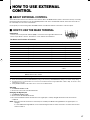
䡵 HOW TO USE THE RS-232C TERMINAL
You can control the monitor from your PC via the RS-232C terminal.
For details on operating the monitor from the PC, consult your dealer or service centre for details.
1. Cable
Prepare a straight cable with a D-sub connector (9-pin, female) and a D-sub
connector (9-pin, male)
2. Communications Specifications
Baud Rate : 4800/9600/19200 (factory pre-set; 4800)
Data Bits : 8 bits
Parity : No parity
Stop Bits : 1
Flow Control : Hardware (RTS/CTS)
3. Commands
Format
Header ID Command Data CR
Header
! Control from the PC to the monitor
? Reference from the PC to the monitor
@ Answer from the monitor to the PC
ID + Command + Data
B Basic command Characters 00, 01 or No data
D Command for adjusting the picture size 00 ~ 07 –20 ~ +20
S Command for adjusting the picture quality 00 ~ 05 –20 ~ +20
M Command for selecting the menu item 00 ~ 0E 00, 01, 10, 11
F Command for selecting the menu item 00 ~ 07 00, 01
W Command for adjusting the white balance 00 ~ 05 –256 ~ +255
C Command for inquiring for the monitor’s status 00 0 ~ 655
During Communication from the PC to the Monitor
The monitor receives the data when DSR remains ON (high) and CTS is set to ON.
During Communication from the Monitor to the PC
The monitor sends the data when both DSR and DCD are set to ON and RTS is set to ON.
Communication Procedures
The following is the communication procedures.
1. Starting the communication
Receives the connection command (!BCN1Cr) from the PC [ Sends the monitor’s status (@BOKCr) to the PC
2. Performing the external control
Receives the control command (!XXXXCr) from the PC [ Sends the monitor’s status (@BOKCr) to the PC
* The monitor repeats these receiving and sending if necessary.
3. Terminating the communication
Receives the termination command (!BCN0Cr) [ Sends the monitor’s status (@BOKCr) to the PC
* After sending the data to the monitor, the PC must first receive the data from the monitor and then send the next command
because the communication is performed in a hand-shake system. If the PC does not receive the status from the monitor after
sending the command, re-send the command.
4
3
2
1
9
8
5
7
6
Pin No. Signal
1 DCD (Data Carrier Detect)
2 RD (Recive Data)
3 TD (Transmit Data)
4 DTR (Data Terminal Ready)
5 GND (Ground)
6 DSR (Data Set Ready)
7 RTS (Request To Send)
8 CTS (Clear To Send)
9 RI (Ring Indication)
18

ENGLISH
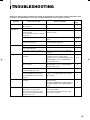
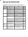
Problems
No power supply
No picture with
the power on
No sound
Wrong colour
Unnatural picture
Shaking picture
Points to be checked
Is the power plug loosened or
disconnected?
Is the signal cable disconnected?
Is the power of the connected
component ON?
Is the signal output from the connected
component?
Is the input signal selected correctly?
Is the input signal adapted to the
monitor’s specification?
Is the audio cable disconnected?
Is the audio signal output from the
connected component?
Is the volume output set to minimum?
Has the picture adjustment been
changed?
Has the WHITE BALANCE setting
been changed?
Are any cables connected to the
component/RGB input card?
Has the correct signal been input to the
component/RGB input card and the
correct INPUT been selected on the
monitor?
Has [CONTRAST] or [BRIGHT] been
changed?
Is the monitor close to a motor,
transformer or any other device
generating a strong magnetic field?
(a fan, fluorescent light, laser printer,
another monitor, etc.)
Measures (Remedy)
Firmly insert the power plug.
Connect the signal cable firmly.
Turn on the power of the connected component
and set it correctly.
Select the correct input with the INPUT SELECT
buttons.
Check that the input signal format corresponds to
the installed input card format.
Connect the audio cable firmly.
Set the connected component correctly.
Adjust the speaker volume with the VOLUME
+/– buttons.
Set each picture adjustment knob to the standard
(centred) position. Or, set each picture
adjustment item in [ PICTURE SUB ADJ.] in the
<SETUP MENU> screen to Standard (00) (or
use the [reset] function).
Set each [COLOR TEMP./BAL.] item in the
<SETUP MENU> screen to Standard (000) (or
use the [reset] function).
Connect each signal cable firmly.
Select INPUT A/C/E when the component signal
is input, or select INPUT B/D/F when the RGB
signal is input.
Adjust the CONTRAST or BRIGHT picture
adjustment knobs.
Or, adjust the [CONTRAST] or [BRIGHT] item in
[PICTURE SUB ADJ.] in the <SETUP MENU>
screen.
Move the monitor away from the device until the
picture stops shaking.
Connect the power plug to another AC outlet
away from the former one.
TROUBLESHOOTING
Solutions to common problems related to your monitor are described here. If none of the solutions presented here solve
the problem, unplug the monitor and consult a JVC-authorised dealer or service centre for assistance.
Reference
pages
5
6, 7
—
5, 8
6, 7
6, 7
—
4
9, 14
15
6
6
14
—
19

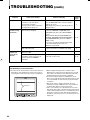
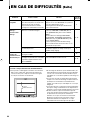
Problems
Irregular colour
Wrong picture
position, wrong
picture size
Front panel
buttons and
knobs do not
function
Points to be checked
Is the monitor placed or moved close to
a speaker or any other device
incorporating a magnet?
Has the position of the monitor been
changed with the power on?
Has the picture position, size or
distortion been changed?
Have the UNDER SCAN or ASPECT
button been pressed?
Has the CONTROL LOCK function
been set to ON?
Has the monitor’s setting been
changed to enable control from an
external unit via the REMOTE
terminals?
Measures (Remedy)
Move the device away from the monitor.
Press the DEGAUSS button on the front panel to
degauss the screen.
When degaussing, wait more than 30 minutes for
maximum effect.
Adjust the picture size (H SIZE, V SIZE) or
position (H. POSITION, V. POSITION) in the
[SIZE/POSI. ADJ.] item in the <SETUP MENU>
screen.
Adjust the picture distortion (PINCUSHION, PIN.
BALANCE, TRAPEZOID and PARALLELOGRAM)
in the [DISTORTION ADJ.] item in the <SETUP
MENU> screen.
It may not be possible to expand the picture due
to the selected input mode. In this case,
adjustment is impossible.
When the UNDER SCAN or ASPECT button is
lit, press each button to invalidate each setting.
Set the CONTROL LOCK function to OFF.
Change the setting of the external control to
control the monitor locally.
The following are not malfunctions:
● You may see two horizontal lines on the monitor. They are
the shadows of the “damper lines” that are necessary for
composing the monitor. These lines are not a malfunction.
● When a bright still image (such as a white cloth) is
displayed for a long period, it may appear to be coloured.
This is due to the structure of the cathode ray tube and
will disappear when another image is displayed.
● You may sometimes experience a mild electric shock
when you touch the picture tube. This phenomenon is due
to a normal buildup of static electricity on the CRT and is
not harmful.
● The monitor emits a strange sound when the room
temperature changes suddenly. This is only a problem if
an abnormality appears on the screen as well.
● If two or more monitors are operated next to each other,
their images may shake or be distorted. This phenomenon
is due to mutual interference; it is not a malfunction. Move
the monitors away from each other until the interference
disappears or turn the power off on any monitor that is not
being used.
VOLUME
SLOT 1
A
B
DEGAUSS
MENU
BLUE
CHECK
ASPECT
AREA
MARKER
UNDER
SCAN
PULSE
CROSS
COLOR
OFF
SLOT 2
C
D
SLOT 3
POWER
E
F
INPUT SELECT
TROUBLESHOOTING (cont.)
Reference
pages
4
15, 16
4
16
17, 18
Damper line
20
La page est en cours de chargement...
La page est en cours de chargement...
La page est en cours de chargement...
La page est en cours de chargement...
La page est en cours de chargement...
La page est en cours de chargement...
La page est en cours de chargement...
La page est en cours de chargement...
La page est en cours de chargement...
La page est en cours de chargement...
La page est en cours de chargement...
La page est en cours de chargement...
La page est en cours de chargement...
La page est en cours de chargement...
La page est en cours de chargement...
La page est en cours de chargement...
La page est en cours de chargement...
La page est en cours de chargement...
La page est en cours de chargement...
La page est en cours de chargement...
La page est en cours de chargement...
La page est en cours de chargement...
La page est en cours de chargement...
La page est en cours de chargement...
La page est en cours de chargement...
La page est en cours de chargement...
La page est en cours de chargement...
La page est en cours de chargement...
-
 1
1
-
 2
2
-
 3
3
-
 4
4
-
 5
5
-
 6
6
-
 7
7
-
 8
8
-
 9
9
-
 10
10
-
 11
11
-
 12
12
-
 13
13
-
 14
14
-
 15
15
-
 16
16
-
 17
17
-
 18
18
-
 19
19
-
 20
20
-
 21
21
-
 22
22
-
 23
23
-
 24
24
-
 25
25
-
 26
26
-
 27
27
-
 28
28
-
 29
29
-
 30
30
-
 31
31
-
 32
32
-
 33
33
-
 34
34
-
 35
35
-
 36
36
-
 37
37
-
 38
38
-
 39
39
-
 40
40
-
 41
41
-
 42
42
-
 43
43
-
 44
44
-
 45
45
-
 46
46
-
 47
47
-
 48
48


Panasonic BT-H1700P Operating Instructions Manual
- Catégorie
- Téléviseurs
- Taper
- Operating Instructions Manual
- Ce manuel convient également à
dans d''autres langues
- English: Panasonic BT-H1700P
Documents connexes
Autres documents
-
JVC Computer Monitor DT-V1710CG Manuel utilisateur
-
-
Sony Ericsson PVM-20M4A Manuel utilisateur
-
JVC TM-A101G Manuel utilisateur
-
Sony PVM-9L3 Manuel utilisateur
-
Hitachi SK-HD2200 Operating Instructions Manual
-
NEC XT4100 Le manuel du propriétaire
-
Sanyo POA-MD17SDID - Projector Terminal Expansion Board Manuel utilisateur