Ideal 120V AC GFCI Receptacle/Voltage Tester Mode d'emploi
- Taper
- Mode d'emploi

Instrucciones en español adentro / Instructions en français
à l’intérieur
61-517 GFCI
Receptacle/VoltageTester
Operation and Safety Manual
IDEAL® Test and Measurement

2
Notes

Introduction .............................................. 3
Contacting IDEAL INDUSTRIES, INC ................. 3
Safety Information ...................................... 4
Warnings ...............................................................5-6
Cautions ...................................................................6
Symbols ................................................................... 7
Operation............................................. 8-15
Identification and description of operating
controls and functions ..........................................8-9
Operating Features ................................................. 10
Meter Operation ...............................................11-12
Voltage and Polarity ........................................ 11
Testing a GFCI .................................................12
Polarity Indications Table ....................................... 13
Functions Operation Table ......................................14
Functions Indication Table .....................................14
Electrical Specifications .........................................15
Environmental Specifications ........................15
Mechanical .............................................16
EMC / EMI ...............................................16
FCC ................................................16
Safety ................................................16
Maintenance and Service ............................17
Disposal and Warranty ................................18
3
Notes

Introduction
The IDEAL 61-517 GFCI Receptacle Tester is a 120V AC plug in outlet
tester that indicates proper polarity or mis-wired outlets via Green and
Red LEDs and line voltage via a LCD. It also tests for GFCI functioning.
Contacting IDEAL INDUSTRIES, INC.
To contact IDEAL INDUSTRIES, INC., call one of the following
telephone numbers:
IDEAL Industries USA Customer Service
• Phone Number: 800-435-0705
• Email: [email protected]
IDEAL Industries Canada Customer Service
• Phone Number: 905-683-3400
• Email: [email protected]
IDEAL Industries EMEA
• Phone Number: +44 (0)1925 444 446
• Email: eur[email protected]
IDEAL Industries Australia
• Phone Number: +61 3 9562 0175
• Email: [email protected]
Or visit the IDEAL Electrical Website at www.idealind.com
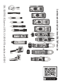
To register your product, find manuals, watch videos, simply scan
this QR code.
4
Arc Flash and Shock Hazard, Proper PPE Required. Follow all safety
procedures, wear proper PPE in accordance to NFPA 70E. Read and
fully understand the instruction manual prior to using this product.
Failure to comply can result in serious injury or death.

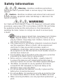
Warning - Identifies conditions and actions
that could result in possible death or serious injury if the hazard is
realized.
Caution - Identifies conditions and actions that could result
in meter damage, equipment under test damage or data loss if the
hazard is realized.
WARNING
Safety Information
Arc Flash and Shock Hazard, Proper PPE Required. Follow all safety
procedures, wear proper PPE in accordance to NFPA 70E and follow
the guidelines below and the instructions in this manual when
operating the meter. Failure to comply can result in serious injury
or death.
• Choking Hazard, Small Parts. Keep Away from Children.
Sharp Objects Hazard, This is not a toy. It is not for use or
play by children. Keep Away from Children. Failure to do so
can result in serious injury.
• Only experienced or technically competent consumers should
use this equipment. When in doubt, call an experienced
electrician to make any and all necessary repairs or
installations. At all times, perform any necessary work on a
de-energized circuit that has had its circuit breaker turned off
and has been locked out.
• Use the Meter only as specified in this manual or protection
provided by the Meter can be compromised.
• Before using or connecting the Meter, visually inspect it
to ensure the cases are not cracked and the back case is
securely in place. Do not use if the Meter appears damaged.
• This Meter is intended for use by qualified electricians.
Follow NFPA 70E Standards for Electrical Safety in the
Workplace when using this Meter.
• Do not use without the batteries correctly in place and the
battery door closed and secured.
• Do not use Meter if it operates incorrectly as protection may
be compromised. When in doubt, have the Meter serviced.
• When servicing the Meter, use only specified replacement
parts. 5

Arc Flash and Shock Hazard, Proper PPE Required. Follow all safety
procedures, wear proper PPE in accordance to NFPA 70E and follow
the guidelines below and the instructions in this manual when
operating the meter. Failure to comply can result in serious injury
or death.
• Have the Meter serviced only by qualified service personnel.
• Do not use the Meter around explosive gas, dust, or vapor, or
during electrical storms, or in wet environments.
• Do not apply more than the rated voltage, as marked on the
Meter, between the terminals or between any terminal and
earth ground.
• To avoid false readings that can lead to electrical shock
and injury, replace the batteries as soon as the low battery
indicator ( ) appears.
• Voltages exceeding 30VAC or 60VDC pose a shock hazard
so use caution.
• Do not work alone so that assistance can be rendered in an
emergency.
• Use extreme caution when working around bare conductors.
Contact with the conductor could result in electric shock.
• Adhere to local and national safety codes. Individual
protective equipment must be used to prevent shock and arc
blast injury where hazardous live conductors are exposed.
• Never operate the Meter with the back cover removed or the
case open.
• Cancer and Reproductive Harm - www.P65Warnings.ca.gov
6
Meter damage, equipment under test damage or data loss can occur if
the following guidelines are not adhered to.
• Clean the case and accessories with a damp cloth and mild
detergents only. Do not use abrasives or solvents. Make sure
the meter is completely dry before use.
CAUTION
WARNING

CAUTION
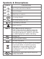
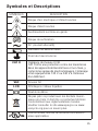
Symbols & Descriptions
SYMBOL DESCRIPTION
Arc Flash and Shock Hazard
Shock Hazard
Warning or Caution
Choking Hazard
AC (Alternating Current)
Low Battery Indicator
Earth Ground
CAT II IEC Measurement Category II
CAT II has protection against transients
in fixed and non-fixed powered devices
including appliances, lighting, and 120V
or 240V equipment inside a building.
VAC Voltage AC
LCD Liquid Crystal Display
Double Insulation
Do not dispose of this product as unsorted
municipal waste. It must be properly
disposed of in accordance with local
regulations. Please see www.epa.gov
or www.erecycle.org for additional
information.
Conforms to applicable North American
Safety Standards
7

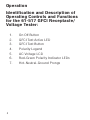
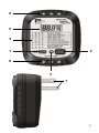
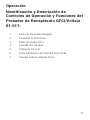
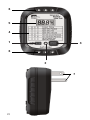
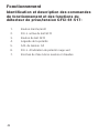
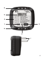
Identification and Description of
Operating Controls and Functions
for the 61-517 GFCI Receptacle/
Voltage Tester:
1. On Off Button
2. GFCI Test Active LED
3. GFCI Test Button
4. Polarity Legend
5. AC Voltage LCD
6. Red-Green Polarity Indicator LEDs
7. Hot-Neutral-Ground Prongs
8
Operation

9
5
1
4
3
6
2
6
7

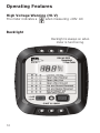
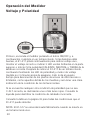
High Voltage Warning (HI-V)
The meter indicates a when measuring >30V AC
Backlight
10
Operating Features
Backlight is always on when
meter is functioning.

11
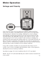
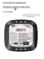
Meter Operation
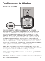
Voltage and Polarity
First, turn the meter on by pressing the ON/OFF Button and then
insert into an outlet. If the batteries are good, the 61-517 will beep
continuously to indicate live voltage, display the correct voltage,
and indicate 3 bright green LEDS on the top and the bottom IF the
HOT NEUTRAL and GROUND polarity of the outlet is correct. After
removing the 61-517 from an outlet it will continue to display the
polarity LED’s and measured voltage value for 5 seconds and shut off
after 3 minutes of inactivity. This gives the user time to unplug from
hard to reach or limited access outlets such as those behind furniture
and still have a clear indication of the outlets condition.
If any other polarity condition is encountered other than correct
H-N-G, one or more red lights will illuminate. Refer to the legend to
identify the incorrect wiring condition.
See table on page 13 for all conditions the 61-517 can detect.
NOTE: The 61-517 will automatically turn itself on when inserted into
a live outlet.

12
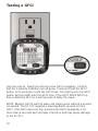
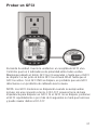
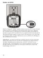
Testing a GFCI
Turn the unit on. Insert the unit into a live GFCI receptacle. Confirm
that the 3 polarity indicators are all green. Press and hold the GFCI
button for 6 seconds or until the GFCI trips. The light next to the GFCI
button will turn RED until the GFCI trips. If the GFCI DOES NOT trip
then a defective GFCI or a wiring issue is likely the cause.
NOTE: Modern GFCI’s will trip when self testing even without a ground
connected. The 61-517 requires a low impedance ground to trip a
GFCI. If the GFCI does not trip, pressing the GFCI repeatedly or for
more than 6 seconds will not make it function and may cause damage
to the 61-517.

13
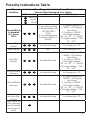
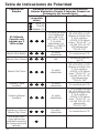
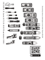
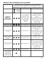
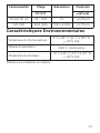
Polarity Indications Table
Wire
Condition Indication When Plugged Into Outlet (Values Maintained for 5
Seconds After Unplugging from Outlet)
LED Indication Buzzer LCD display
Green (G)
Red (R)
Off (O)
Correct Wiring
is indicated
by 3 Green
LED’s
1. 5s continuous beep
(if Voltage between 108
~ 132 VAC(120+/-
10%))
2. 5s intermittent beep
if voltage <108VAC or
>132VAC
1. If Voltage is between 30
~ 150VAC, LCD Displays
Live voltage
2. If voltage is <30VAC,
LCD toggles between
“”30--LO--30””; if >150VAC,
LCD toggles between “”150--
OL---150””
Open (No)
Neutral 5s intermittent beep Err displayed on LCD
Open (No) Hot NA 000V display on LCD
Open (No)
Ground 5s intermittent beep
1. If Voltage is between 30
~ 150VAC, LCD Displays
Live voltage
2. If voltage is <30VAC,
LCD toggles between
“”30--LO--30””; if >150VAC,
LCD toggles between “”150--
OL---150””
Hot and Ground
Reversed 5s intermittent beep Err displayed on LCD
Hot and Neutral
Reversed 5s intermittent beep
1. If Voltage is between 30
~ 150VAC, LCD Displays
Live voltage
2. If voltage is <30VAC,
LCD toggles between
“”30--LO--30””; if >150VAC,
LCD toggles between “”150--
OL---150””
Hot on Ground
and Open (No)
Ground 5s intermittent beep Err displayed on LCD
One or more red
LED’s indicates
incorrect polarity
and a miswired
outlet.

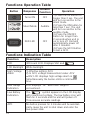
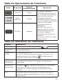
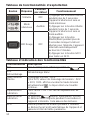
Button Response Default
Function Operation
Turns ON OFF 1) Press the on button for
longer than 2 sec. The unit
will turn on and be in the
silent mode.
2) Press the ON button for
less than 1 sec. The unit
will turn on and be in the
audible mode.
3) Press the ON/OFF
button for longer than
2 seconds when unit is
on to turn off. Unit will
automatically power off
after 2 minutes.
4) Press the GFCI Button
to test a GFCI.
Silent Mode Audible
RED LED OFF
14
Functions Indication Table
Function Description
LCD 300 count LCD. Displays VAC and
LCD Backlight White backlight.
High Voltage
Alarm
1) Effective setting: ACV.
2) In ACV, voltage measurement value: ACV
≥30V, LCD displays high voltage alarm is
Simultaneously the buzzer emits a continuous
tone.
Over Range
Indication
LCD displays “OL” when over range is
encountered.
Low Battery
Indication
The “ ” symbol appears in the LCD display
with insufficient voltage. The low battery icon will
flash for 5 seconds and the unit will power off.
This ensures accurate readings.
APO No button presses for 3 minutes will be automat-
ically cause the unit to shut down and enter the
low-power state.
Functions Operation Table

Functions Indication Table
Functions Operation Table
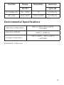
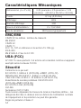
15
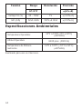
Function Range Resolution Accuracy
61-517 ±(a%+b)
AC Voltage (V) 30 - 150V 1V ±(3.0%+2)
GFI (mA) 6mA~9mA 102V,>6.0mA ±(2.0%+5)
Environmental Specifications
Operating Temperature: 32ºF to 104ºF (0ºC to 40ºC)
(<80%RH)
Operating Altitude: 6500 ft (2000 m)
Storage Temperature: 14ºF to 122ºF (-10ºC to 50ºC)
(<80%RH)
Intended for indoor use.

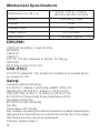
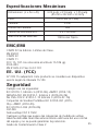
Mechanical Specifications
Dimensions: (L x W x H) 3.25 in. x 2.6 in. x 1.25 in.
(85 mm x 65 mm x 33 mm)
Weight: 0.25 LBS (0.1 KG)
Display: LCD
Display Count: 300
Power Source: 2 x 1.5V AAA
Battery Life: 100 Hours Typical
EMC/EMI
16
CISPR 22 3rd Edition. Class B Limits.
EN 55032
CISPR 32
CISPR 11
FCC 15. 107 with reference to Section 15.109 (g).
ICES-003
EN 61326-2-2 Sec 6.4.2.101
USA (FCC)
47 CFR 15 subpart B. This product is considered an exempt device
per clause 15.103.
Safety
Complies with the following:
IEC 61010-1, Edition 3 (2010-06) +AMD1 (2016-12)
ANSI/UL/IEC EN 61010-1, Edition 3 (2016-04-29)
CSA-C22.2 No. 61010-1-12 Edition 3 (2019-07-19)
IEC 61010-031 Hand-held Probe Assemblies (2015-
05)+AMD1(2018-05)
IEC 61010-2-033 (2019-06)
UL1436
Overvoltage CAT II 150V.
Any voltages exceeding the defined maximum voltage measurement
categories described above are outside the normal use of the equip-
ment and protection cannot be guaranteed.
Pollution Degree Class 2

Safety
17
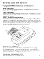
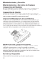
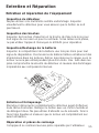
Equipment Maintenance and Service
Meter Inspection
Do not use if meter appears damaged. Visually inspect the meter to
ensure case is not cracked.
Prong Inspection
Inspect the insertion prongs and ground pin for any signs of corrosion
and for straightness. If the blades are bent, do no use the unit. Return
to IDEAL for service.
Battery Inspection/Replacement
Inspect the battery compartment monthly for any signs of degradation.
Low battery voltages will cause inaccuracies in readings. Remove the
batteries for storage or if the meter will not be used for longer than one
month. Battery leakage will compromise the safety of the meter and
cause irreparable damage to internal components.
Maintenance and Storage
Switch off and disconnect the meter completely before carrying
out any maintenance. Clean the case with a damp cloth and mild
detergent. Do not use abrasives or solvents. Keep away from liquids
and ensure the meter is completely dry before use.
Service and Replacement Parts
This unit has no user-serviceable parts.
Maintenance and Service

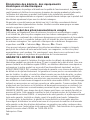
In order to preserve, protect and improve the quality of the environment, protect human
health and utilize natural resources prudently and rationally, the user should return
unserviceable product to relevant facilities in accordance with statutory regulations. The
crossed-out wheeled bin indicates the product needs to be disposed separately and not
as municipal waste.
Do not dispose of this product as unsorted municipal waste. It must be properly disposed
of in accordance with local regulations. Please see www.epa.gov or www.erecycle.org for
additional information.
The user is legally obliged to return used batteries and accumulators. Disposing used
batteries in household waste is prohibited! Batteries/accumulators containing hazardous
substances are marked with the crossed-out wheeled bin. The symbol indicates that the
product is forbidden to be disposed via domestic refuse. The chemical symbols for the
respective hazardous substances are Cd = Cadmium, Hg = Mercury, Pb = Lead.
You can return used batteries/accumulators free of charge to any collecting point of your
local authority, our stores, or where batteries/accumulators are sold. Consequently, you
must comply with your legal obligations and contribute to environmental protection.
Disposal of Waste, Electrical & Electronic
Equipment
Disposal of Used Batteries/Accumulators
TWO YEAR LIMITED WARRANTY
This tester is warranted to the original purchaser against defects in material and
workmanship for a period of two (2) years from date of purchase. With proof of purchase
from an authorized IDEAL distributor, a defective tester will be repaired or replaced with the
same product or a functionally equivalent product, at the option of IDEAL INDUSTRIES,
INC. during the warranty period, subject to verification of the defect or malfunction.
Warranty does not cover consumables such as fuses, batteries, and excludes defects
caused by leakage from batteries, abuse, mishandling, dropping, ordinary wear and
tear, misuse, neglect, unauthorized repair, improper use, alterations, accidents or any
causes beyond IDEAL’s reasonable control. Consequential or incidental damages are not
recoverable under this warranty. Some states do not allow the exclusion or limitation
of incidental or consequential damages, so the above limitation or exclusion may not
apply to you. This LIMITED WARRANTY gives you specific legal rights, which vary from
state to state. This warranty constitutes the sole and exclusive remedy of the purchaser
and the exclusive liability of IDEAL, and is in lieu of any and all other warranties, and
expressly disclaims all other warranties, implied, or statutory as to merchantability, fitness
for purpose sold, description, quality productiveness, or any other matter. No agent,
distributor or other supplier has the authority to modify or amend this warranty or make
other representations or warranties other than those contained in this warranty without
express written authorization from IDEAL. For warranty service, call IDEAL customer
service at 1-800-435-0705.
Made in China.
18

IDEAL INDUSTRIES, INC. Sycamore, IL 60178, U.S.A. 800-435-0705 www.Idealind.com ND 9004-2
Scan the barcode on the right to see the new IDEAL T&M Product Line

Instrucciones en español adentro / Instructions en français à l’intérieur
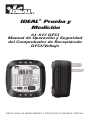
61-517 GFCI
Manual de Operación y Seguridad
del Comprobador de Receptáculo
GFCI/Voltaje
IDEAL® Prueba y
Medición
La page est en cours de chargement...
La page est en cours de chargement...
La page est en cours de chargement...
La page est en cours de chargement...
La page est en cours de chargement...
La page est en cours de chargement...
La page est en cours de chargement...
La page est en cours de chargement...
La page est en cours de chargement...
La page est en cours de chargement...
La page est en cours de chargement...
La page est en cours de chargement...
La page est en cours de chargement...
La page est en cours de chargement...
La page est en cours de chargement...
La page est en cours de chargement...
La page est en cours de chargement...
La page est en cours de chargement...
La page est en cours de chargement...
La page est en cours de chargement...
La page est en cours de chargement...
La page est en cours de chargement...
La page est en cours de chargement...
La page est en cours de chargement...
La page est en cours de chargement...
La page est en cours de chargement...
La page est en cours de chargement...
La page est en cours de chargement...
La page est en cours de chargement...
La page est en cours de chargement...
La page est en cours de chargement...
La page est en cours de chargement...
La page est en cours de chargement...
La page est en cours de chargement...
La page est en cours de chargement...
La page est en cours de chargement...
La page est en cours de chargement...
-
 1
1
-
 2
2
-
 3
3
-
 4
4
-
 5
5
-
 6
6
-
 7
7
-
 8
8
-
 9
9
-
 10
10
-
 11
11
-
 12
12
-
 13
13
-
 14
14
-
 15
15
-
 16
16
-
 17
17
-
 18
18
-
 19
19
-
 20
20
-
 21
21
-
 22
22
-
 23
23
-
 24
24
-
 25
25
-
 26
26
-
 27
27
-
 28
28
-
 29
29
-
 30
30
-
 31
31
-
 32
32
-
 33
33
-
 34
34
-
 35
35
-
 36
36
-
 37
37
-
 38
38
-
 39
39
-
 40
40
-
 41
41
-
 42
42
-
 43
43
-
 44
44
-
 45
45
-
 46
46
-
 47
47
-
 48
48
-
 49
49
-
 50
50
-
 51
51
-
 52
52
-
 53
53
-
 54
54
-
 55
55
-
 56
56
-
 57
57


