
Operating Instructions and Parts Manual
14-inch Cabinet Saw
Model PM3000B
Powermatic
427 New Sanford Road
LaVergne, Tennessee 37086 Part No. M-PM3753B
Ph.: 800-274-6848 Edition 3 03/2019
www.powermatic.com Copyright © 2017 Powermatic
This .pdf document is bookmarked

1.0 IMPORTANT SAFETY
INSTRUCTIONS
READ ALL INSTRUCTIONS BEFORE USING
THIS MACHINE.
WARNING – To reduce risk of injury:
1. Read and understand the entire owner’s
manual before attempting assembly or
operation.
2. Read and understand the warnings posted on
the machine and in this manual. Failure to
comply with all of these warnings may cause
serious injury.
3. Replace the warning labels if they become
obscured or removed.
4. This table saw is designed and intended for
use by properly trained and experienced
personnel only. If you are not familiar with the
proper and safe operation of a table saw, do
not use until proper training and knowledge
have been obtained.
5. Do not use this table saw for other than its
intended use. If used for other purposes,
Powermatic disclaims any real or implied
warranty and holds itself harmless from any
injury that may result from that use.
6. Always wear approved safety glasses or face
shield while using this table saw. Everyday
eyeglasses only have impact resistant lenses;
they are not safety glasses.
7. Before operating this table saw, remove tie,
rings, watches and other jewelry, and roll
sleeves up past the elbows. Do not wear loose
clothing. Confine long hair. Non-slip footwear
or anti-skid floor strips are recommended. Do
not wear gloves.
8. Wear ear protectors (plugs or muffs) during
extended periods of operation.
9. Do not operate this machine while tired or
under the influence of drugs, alcohol or any
medication.
10. Make certain the machine is properly
grounded.
11. Make all machine adjustments or maintenance
with the machine unplugged from the power
source. A machine under repair should be
RED TAGGED to show it must not be used
until maintenance is complete.
12. Remove adjusting keys and wrenches. Form a
habit of checking to see that keys and
adjusting wrenches are removed from the
machine before turning it on.
13. Keep safety guards in place at all times when
the machine is in use. If removed for
maintenance purposes, use extreme caution
and replace the guards immediately.
14. Check the alignment of the riving knife, fence
and miter slot to the blade. A caution decal is
installed on each guard to remind the operator
of the dangers of improper machine operation.
15. Check damaged parts. Before further use of
the machine, a guard or other part that is
damaged should be carefully checked to
determine that it will operate properly and
perform its intended function. Check for
alignment of moving parts, binding of moving
parts, breakage of parts, mounting and any
other conditions that may affect its operation.
A guard or other part that is damaged should
be properly repaired or replaced.
16. Provide for adequate space surrounding work
area and non-glare, overhead lighting.
17. Keep the floor around the machine clean and
free of scrap material, oil and grease.
18. Keep visitors a safe distance from the work
area. Keep children away.
19. Make your workshop child proof with padlocks,
master switches or by removing safety keys.
20. Give your work undivided attention. Looking
around, carrying on a conversation and “horse-
play” are careless acts that can result in
serious injury.
21. Maintain a balanced stance at all times so that
you do not fall or lean against the blade or
other moving parts. Do not overreach or use
excessive force to perform any machine
operation.
22. Use the right tool at the correct speed and
feed rate. Do not force a tool or attachment to
do a job for which it was not designed. The
right tool will do the job better and safer.
23. Use recommended accessories; improper
accessories may be hazardous.
24. Maintain tools with care. Keep blade sharp and
clean for the best and safest performance.
Follow instructions for lubricating and changing
accessories.
25. Check the saw blade for cracks or missing
teeth. Do not use a cracked or dull blade or
one with missing teeth or improper set. Make
sure the blade is securely locked on the arbor.
26. Keep hands clear of the blade area. Do not
reach past the blade to clear parts or scrap
with the saw blade running. Never saw
freehand. Avoid awkward operations and hand
positions where a sudden slip could cause
your hand to contact the blade.

3
27. Do not attempt to saw boards with loose knots
or with nails or other foreign material, on its
surface. Do not attempt to saw twisted, warped
or bowed stock unless one edge has been
jointed for guiding purposes prior to sawing.
Excessively warped stock should not be used.
28. Do not attempt to saw long or wide boards
unsupported where spring or weight could
cause the board to shift position.
29. Always use the riving knife, blade guard, push
stick and other safety devices for all operations
where they can be used. On operations such
as dadoing or molding where the blade guard
cannot be used, use feather boards, fixtures
and other safety devices and use extreme
caution. Reinstall the riving knife and blade
guard immediately after completing the
operation that required their removal.
30. Be sure the saw blade rotates clockwise when
viewed from the motor side (left side) of the
machine.
31. Turn off the machine before cleaning. Use a
brush or compressed air to remove chips or
debris — do not use bare hands.
32. Do not stand on the machine. Serious injury
could occur if the machine tips over.
33. Never leave the machine running unattended.
Turn the power off and do not leave the
machine until it comes to a complete stop.
34. Remove loose items and unnecessary work
pieces from the area before starting the
machine.
35. Blade should have minimum exposure during
cuts. Adjust blade to approximately 1/8” inch
above surface of workpiece.
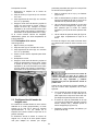
1.1 Kickback
The most common accidents among table saw
users, according to statistics, can be linked to
kickback, the high-speed expulsion of material from
the table that can strike the operator. Kickback can
also result in the operator’s hands being pulled into
the blade.
Kickback Prevention
Tips to avoid the most common causes of
kickback:
Make sure the riving knife is always aligned
with the blade. A workpiece can bind or stop
the flow of the cut if the riving knife is
misaligned, and result in kickback.
Use a riving knife during every cut. The riving
knife maintains the kerf in the workpiece,
which will reduce the chance of kickback.
Never attempt freehand cuts. The workpiece
must be fed parallel to the blade, otherwise
kickback will likely occur. Always use the rip
fence or miter gauge to support the workpiece.
Make sure that rip fence is parallel to blade. If
not, the chances of kickback are very high.
Take the time to check and adjust the rip
fence.
Feed cuts through to completion. Anytime you
stop feeding a workpiece that is in the middle
of a cut, the chance of binding, resulting in
kickback, is greatly increased.
Tips for Kickback Protection
Kickback can happen even if precautions are taken
to prevent it. Listed below are some tips to protect
you if kickback does occur:
Stand to the side of the blade when cutting. An
ejected workpiece usually travels directly in
front of the blade.
Wear safety glasses or a face shield. Your
eyes and face are the most vulnerable part of
your body.
Never place your hand behind the blade. If
kickback occurs, your hand will be pulled into
the blade.
Use a push stick to keep your hands farther
away from the moving blade. If a kickback
occurs, the push stick will most likely take the
damage that your hand would have received.
WARNING: This product can expose you to
chemicals including lead which is known to the
State of California to cause cancer and birth
defects or other reproductive harm. For more
information go to http://www.p65warnings.ca.
gov.
WARNING: Drilling, sawing, sanding or
machining wood products generates wood dust
and other substances known to the State of
California to cause cancer. Avoid inhaling dust
generated from wood products or use a dust
mask or other safeguards for personal
protection.
Wood products emit chemicals known to the
State of California to cause birth defects or
other reproductive harm. For more information
go to http://www.p65warnings.ca.gov/wood.

4
Familiarize yourself with the following safety notices used in this manual:
This means that if precautions are not heeded, it may result in minor injury and/or possible
machine damage.
This means that if precautions are not heeded, it may result in serious or possibly fatal injury.
2.0 Table of contents
Section Page
1.0 IMPORTANT SAFETY INSTRUCTIONS ....................................................................................................... 2
1.1 Kickback ..................................................................................................................................................... 3
2.0 Table of contents ............................................................................................................................................ 4
3.0 About this manual .......................................................................................................................................... 5
4.0 Specifications for PM3000B ........................................................................................................................... 6
5.0 Table Saw terminology ................................................................................................................................... 8
6.0 Setup and assembly ....................................................................................................................................... 9
6.1 Shipping contents ....................................................................................................................................... 9
6.2 Tools required for assembly ....................................................................................................................... 9
6.3 Unpacking and cleanup ............................................................................................................................ 10
6.4 Installing extension wings ......................................................................................................................... 10
6.5 Handwheel, knobs, levers ........................................................................................................................ 11
6.6 Rails and Fence ....................................................................................................................................... 11
6.7 Motor cover .............................................................................................................................................. 11
6.8 Table insert ............................................................................................................................................... 11
6.9 Installing and removing blade ................................................................................................................... 12
6.10 Installing guard/knife assembly .............................................................................................................. 12
6.11 Dust port ................................................................................................................................................. 13
7.0 Electrical connections .................................................................................................................................. 13
7.1 GROUNDING INSTRUCTIONS ............................................................................................................... 13
7.2 Voltage conversion ................................................................................................................................... 14
7.3 Extension cords ........................................................................................................................................ 14
7.4 Magnetic switch and safety key ................................................................................................................ 14
8.0 Adjustments ................................................................................................................................................. 15
8.1 Tools required for adjustments ................................................................................................................. 15
8.2 Fence alignment ....................................................................................................................................... 15
8.3 Blade raising and tilting ............................................................................................................................ 15
8.4 Miter gauge .............................................................................................................................................. 15
8.5 Blade tilt stop adjustment ......................................................................................................................... 16
8.6 Riving knife alignment .............................................................................................................................. 17
8.7 Table to blade alignment .......................................................................................................................... 17
8.8 Belt adjustment ......................................................................................................................................... 18
8.9 Zero-clearance insert setup ...................................................................................................................... 18
9.0 Operations .................................................................................................................................................... 19
10.0 Safety devices ............................................................................................................................................ 23
10.1 Feather board ......................................................................................................................................... 23
10.2 Push stick and push block ...................................................................................................................... 23
11.0 User-maintenance ...................................................................................................................................... 24
11.1 General inspection ................................................................................................................................. 24
11.2 Cleaning ................................................................................................................................................. 24
11.3 Lubrication .............................................................................................................................................. 24
11.4 Arbor/Arbor Bearing Removal ................................................................................................................ 24
11.5 Additional servicing ................................................................................................................................ 24
12.0 Optional accessories .................................................................................................................................. 25
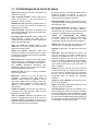
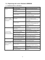
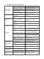
13.0 Troubleshooting PM3000B Cabinet Saw ................................................................................................... 26
13.1 Motor and electrical problems ................................................................................................................ 26
13.2 Mechanical and operational problems .................................................................................................... 26

5
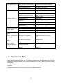
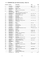
14.0 Replacement Parts ..................................................................................................................................... 27
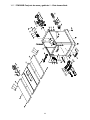
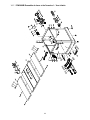
14.1.1 PM3000B Table and Cabinet Assembly – Exploded View .................................................................. 28
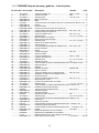
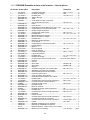
14.1.2 PM3000B Table and Cabinet Assembly – Parts List ........................................................................... 29
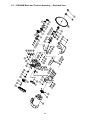
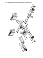
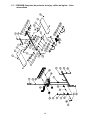
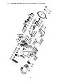
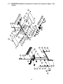
14.2.1 PM3000B Motor and Trunnion Assembly I – Exploded View .............................................................. 30
14.2.2 PM3000B Motor and Trunnion Assembly II – Exploded View ............................................................. 31
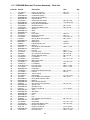
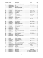
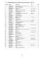
14.2.3 PM3000B Motor and Trunnion Assembly – Parts List ......................................................................... 32
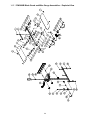
14.3.1 PM3000B Blade Guard and Miter Gauge Assemblies – Exploded View ............................................ 34
14.3.2 PM3000B Blade Guard and Miter Gauge Assemblies – Parts List ..................................................... 35
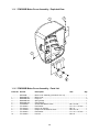
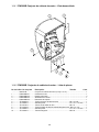
14.4.1 PM3000B Motor Cover Assembly – Exploded View ........................................................................... 36
14.4.2 PM3000B Motor Cover Assembly – Parts List .................................................................................... 36
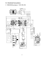
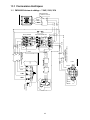
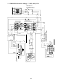
15.0 Electrical Connections ................................................................................................................................ 37
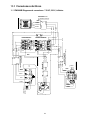
15.1 PM3000B Wiring diagram – 7.5HP, 230V, 3PH ..................................................................................... 37
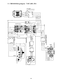
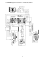
15.2 PM3000B Wiring diagram – 7.5HP, 460V, 3PH ..................................................................................... 38
16.0 Warranty and Service ................................................................................................................................. 39
3.0 About this manual
This manual is provided by Powermatic covering the safe operation and maintenance procedures for a
Powermatic Model PM3000B Cabinet Saw. This manual contains instructions on installation, safety
precautions, general operating procedures, maintenance instructions and parts breakdown. Your machine has
been designed and constructed to provide consistent, long-term operation if used in accordance with the
instructions set forth in this document.
This manual is not intended to be an exhaustive guide to table saw operational methods, use of jigs or after-
market accessories, choice of stock, etc. Additional knowledge can be obtained from experienced users or
trade articles. Whatever accepted methods are used, always make personal safety a priority.
If there are questions or comments, please contact your local supplier or Powermatic. Powermatic can also be
reached at our web site: www.powermatic.com.
Retain this manual for future reference. If the machine transfers ownership, the manual should accompany it.
Read and understand the entire contents of this manual before attempting assembly
or operation! Failure to comply may cause serious injury!

6
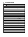
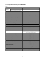
4.0 Specifications for PM3000B
Table 1
Model number PM3000B
Stock numbers Saw only PM3753B
Saw with 50” rip, wood ext. table PM375350K
Motor and Electricals
Motor type Totally enclosed, fan cooled, induction
Horsepower 7-1/2 HP
Motor phase 3 PH
Motor voltage 230/4601 V (prewired 230 V)
Cycle 60 Hz
Listed FLA (full load amps) 18.4/9.2
Motor speed 3450 RPM
Starting amps 120
Running amps (no load) 6.7
Power transfer Poly-V belt
On/off switch Magnetic switch, with safety key
Power cord and plug Not supplied
Recommended circuit size 2 30 A
Sound emission without load 3 91 db at 100cm; 95 dB at 50cm
Arbor and blade
Arbor diameter 1 in. (25.4 mm)
Arbor speed 4500 RPM
Arbor lock yes
Arbor wrench included
Blade included Ø14 in. (356mm), 0.098 in. (2.5mm) thk, 0.138 in. (3.5mm) kerf,
72T, AB, carbide tips
Maximum depth of cut at 90 degrees 5-1/8 in. (130 mm)
Maximum depth of cut at 45 degrees 3-1/2 in. (89 mm)
Maximum rip to right of blade 50 in. (1270 mm)
Maximum rip to left of blade 14 in. (356 mm)
Dado maximum width 13/16 in. (21 mm)
Dado maximum diameter 8 in. (203 mm)
Blade tilt Left, 0° to 45°
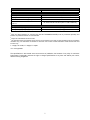
Table
Main table dimensions, L x W 26 x 38 in. (661 x 965 mm)
Table dimensions with wings, L x W 48 x 38 in. (1219 x 965 mm)
Table area in front of blade at maximum height 15-1/2 in. (394 mm)
Table surface from floor 35-1/4 in. (895 mm)
Miter T-slot, W x D 2 slots; 3/4 x 3/8 in. (19 x 10 mm)
Edge bevel Front and rear
Main materials
Main table cast iron
Table insert compact laminate
Extension wings cast iron
Cabinet steel
Base steel
Center trunnion cast iron
Bearing arm cast iron
Pulleys steel

7
Dust collection
Dust port outside diameter 4" (101.6 mm)
Recommended minimum extraction volume 600 CFM (17 CMM)
General Dimensions
Base footprint 26-3/4 x 32-3/16 in. (680 x 818 mm)
Shipping dimensions, saw only, L x W x H 32-1/4 x 44-11/16 x 43-1/2 in. (845 x 1135 x 1105 mm)
Assembled, w/ extension wings only, L x W x H 48 x 38 x 42-7/8 in. (1219 x 965 x 1089 mm)
Assembled, with 50-in. rail set, wood ext. table
L x W x H 84-11/16 x 46-1/2 x 42-7/8 in. (2151 x 1183 x 1089 mm)
Weights
Saw only – net weight (approx.) 467 lb. (212 kg)
Saw only – shipping weight (approx.) 600 lb. (273 kg)
1 Note: For 460V operation, an overload relay (Part No. PM3000B-2107AOR) must be purchased separately and
installed. A qualified electrician is recommended.
2 subject to local/national electrical codes.
3 The specified values are emission levels and are not necessarily to be seen as safe operating levels. As workplace
conditions vary, this information is intended to allow the user to make a better estimation of the hazards and risks
involved only.
L = length, W = width, H = height, D = depth
n/a = not applicable
The specifications in this manual were current at time of publication, but because of our policy of continuous
improvement, Powermatic reserves the right to change specifications at any time and without prior notice,
without incurring obligations.

8
5.0 Table Saw terminology
Arbor: Metal shaft that connects the drive
mechanism to the blade.
Bevel Edge Cut: Tilt of the saw arbor and blade
between 0° and 45° to perform an angled cutting
operation.
Blade Guard: Mechanism mounted over the saw
blade to prevent accidental contact with the cutting
edge.
Crosscut: Sawing operation in which the miter
gauge is used to cut across the grain of the
workpiece.
Dado Blade: Blade(s) used for cutting grooves and
rabbets. A stacked dado set can be used for wider
grooves.
Dado Cut: Flat bottomed groove in the face of the
workpiece made with a dado blade.
Featherboard: Device used to keep a board
against the rip fence or table that allows the
operator to keep hands away from saw blade.
Freehand: Moving the workpiece into the blade
using only the hands, without a fixed positioning
device. (This is a dangerous, unacceptable
procedure – always use appropriate devices to
feed the workpiece through the saw blade during
cutting operations.)
Kerf: The resulting cut or gap made by a saw
blade.
Kickback: An event in which the workpiece is lifted
up and thrown back toward an operator, caused
when a workpiece binds on the saw blade or
between the blade and rip fence (or other fixed
object). To minimize or prevent injury from
kickbacks, see the Operations section.
Miter Gauge: A component that controls the
workpiece movement while performing a crosscut
of various angles.
Non-Through Cut: A sawing operation that
requires the removal of the blade guard and
standard riving knife, resulting in a cut that does
not protrude through the top of the workpiece
(includes dado and rabbet cuts).
The blade guard and riving knife must be re-
installed after performing a non-through cut to
avoid accidental contact with the saw blade during
operation.
Parallel: Position of the rip fence equal in distance
at every point to the side face of the saw blade.
Perpendicular: 90° (right angle) intersection or
position of the vertical and horizontal planes such
as the position of the saw blade (vertical) to the
table surface (horizontal).
Push Board/Push Stick: An instrument used to
safely push the workpiece through the cutting
operation by keeping the operator’s hands at a
distance.
Rabbet: A cutting operation that creates an
L-shaped channel along the edge of the board.
Rip Cut: A cut made along the grain of the
workpiece.
Riving Knife: A metal plate fixed relative to the
blade, which moves with the blade as cutting depth
is adjusted. Thus, it maintains not only the kerf
opening in the workpiece, but also the knife-to-
blade distance. A low-profile riving knife sits lower
than the top edge of the blade, for making a non-
through cut.
Splitter (Spreader): A stationary metal plate to
which the blade guard is attached that maintains
the kerf opening in the workpiece during a cutting
operation. (Powermatic table saws use the superior
riving knife system instead.)
Standard Kerf: 1/8" gap made with a standard
blade.
Straightedge: A tool used to check that a surface
is flat or parallel.
Through Sawing: A sawing operation in which the
workpiece thickness is completely sawn through.
Proper blade height usually allows 1/8" of the top
of blade to extend above the wood stock. Keep the
blade guard down, the anti-kickback pawls down,
and the riving knife in place over the blade.

9
Read and understand the
entire contents of this manual before
attempting set-up or operation. Failure to
comply may cause serious injury.
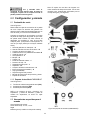
6.0 Setup and assembly
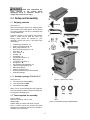
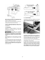
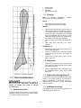
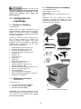
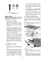
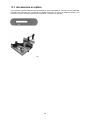
6.1 Shipping contents
See Figure 6-1.
Remove all accessory boxes from shipping pallet.
Remove items from inside cabinet. Do not discard
any packing material until saw is assembled and
running satisfactorily.
Compare contents of your container with parts list
below to make sure all parts are intact. Any
missing parts should be reported to your
distributor. (Check saw first in case parts were
preinstalled.)
1 Cabinet saw with switch – A
2 Cast iron extension wings – B
1 Miter gauge assembly – C
1 Motor cover with hinge pins – D
1 Push stick – E
1 Arbor wrench – F
2 Handles – G
1 Handwheel – H
1 Handwheel lock knob – J
1 Blade guard – K
1 Low profile riving knife – L
1 Riving knife – M
1 Anti-kickback pawl assembly – N
1 Table insert (preinstalled) – O
1 Blade (preinstalled)
1 Product registration card
1 Operating Instructions and Parts Manual
1 Hardware package
6.1.2 Hardware package #PM2000B-HP
See Figure 6-2.
6 Hex cap screws, M10x35 (HP1)
6 Lock washers M10 (HP2)
6 Flat washers M10 (HP3)
NOTE: Fence and rail assemblies with fasteners,
and wood extension tables and legs with fasteners,
are shipped in separate boxes.
6.2 Tools required for assembly
Hex key 2.5mm
Open end wrenches: 14mm, 17mm
Straight edge
Rubber mallet (or hammer with block of wood)
Note: A ratchet wrench with sockets will speed
assembly time. Additional tools may be needed for
assembly of fence and rails.
Figure 6-1 (items not to scale)
Figure 6-2 hardware package (PM2000B-HP)

10
The saw must be discon-
nected from power source during assembly.
Failure to comply may cause serious injury.
6.3 Unpacking and cleanup
1. Use a hoist to lift saw off pallet; or remove
nailed boards holding saw cabinet to pallet and
slide saw off pallet onto floor.
2. The cabinet saw should be placed in an area
with a sturdy level floor, good ventilation and
sufficient lighting. Leave enough space around
the machine for mounting extension tables and
rail assemblies, and loading and off-loading
stock and general maintenance work.
3. Exposed metal surfaces, such as table top and
extension wings, have been given a protective
coating at the factory. This should be removed
with a soft cloth moistened with kerosene or a
cleaner-degreaser. Do not use acetone,
gasoline, or lacquer thinner for this purpose.
Do not use solvents on plastic parts, and avoid
using an abrasive pad as it may scratch
surfaces.
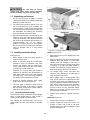
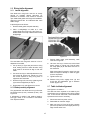
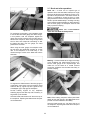
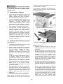
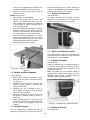
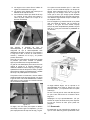
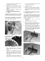
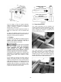
6.4 Installing extension wings
See Figure 6-3.
1. Mating edges of table and wings should be
clean and free of burrs.
2. Attach an extension wing (B) to saw table.
(Extension wings are identical). Use three
screws, lock washers and flat washers (HP-
1/2/3). Lightly snug screws with 17mm wrench
or socket. Do not fully tighten yet.
Assembly Tip: If you are doing this without an
assistant, lift extension wing perpendicular to
table edge. Install center screw and washers,
and make snug. Then pivot wing parallel to
saw table to insert remaining two screws.
3. Repeat for opposite extension wing. Lightly
snug screws. Do not fully tighten yet.
4. The front edge of extension wings must be
flush with front edge of saw table. If needed,
tap front edge of wing with a rubber mallet to
make flush. See Figure 6-4.
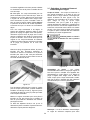
6.4.1 Leveling extension wings
Level extension wings to saw table using a straight
edge. A metal straight edge is ideal, though a
carefully jointed board may also be used.
Two methods are described below: one using a
rubber mallet, the other using clamps on the table
edges.
Figure 6-3: installing accessories
Figure 6-4: leveling extension wings, method 1
Method 1 (Figure 6-4):
1. Shift extension wing so it is slightly above saw
table surface.
2. Begin by tightening the three screws beneath
extension wing that secure it to saw table.
Tighten these just enough to hold wing in
place but loose enough to change wing height
by tapping on it. (Tap with rubber mallet, or
hammer over a flat block of wood. Never use a
steel-faced hammer directly on the tables.)
3. Lay straight edge across saw table and
extension wing, extending it out past edge of
wing as shown in Figure 6-4.
4. Move straight edge to several places along
wing, as you continue to nudge wing level with
saw table. Also brush your fingertips over the
seam to ensure the transition feels smooth. As
each area of wing becomes flush with table,
tighten screw under that area. Continue until
all three screws are fully tightened. NOTE:
Make sure front edge of wing remains flush
with front edge of saw table.
5. Repeat above steps for opposite extension
wing.
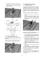
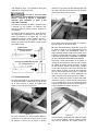
Method 2 (Figure 6-5):
1. Follow steps 1 through 3 from Method 1.
2. Position clamps over seam, one at front, one
at back of table. Use a pad or flat block
beneath clamp jaw to prevent damage to table
surface. See Figure 6-5.

11
3. Tighten both clamps to align front and back
edges of tables. Make sure front edge of wing
remains flush with front edge of saw table.
4. Tighten screws incrementally, and position
straight edge at various places across seam,
especially checking at the center. Make further
adjustments as needed.
5. Fully tighten screws.
Figure 6-5: leveling extension wings, method 2
6.5 Handwheel, knobs, levers
See Figure 6-3.
1. Remove tape from around shaft to expose
threads and shaft key (H1, Figure 6-3).
2. Ensure that set screw in handwheel (H2) is
backed out sufficiently to prevent interference.
3. Ensure that key is in slot. Slide handwheel
onto shaft, aligning keyway with key.
4. Push handwheel on shaft as far as it will go,
then tighten set screw (H2).
5. Install locking knob (J, Figure 6-3) and handles
(G). Use wrench on flat of handles to tighten
against handwheels.
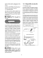
6.6 Rails and Fence
With extension wings properly mounted, the rails
and Accu-Fence® assembly can now be mounted
to saw. Consult manual no. M-2195079B which
accompanies the fence, then proceed with sect.
6.7 below.
6.6.1 Switch bracket
See Figure 6-6.
The switch bracket is installed at the same time as
guide tube. Use two screws with washers which
are provided with the rails.
Figure 6-6: installing switch
6.6.2 Wood Extension Table
For instructions on mounting the accessory wood
extension table, consult Accu-Fence manual, no.
M-2195079B.
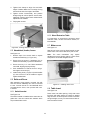
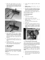
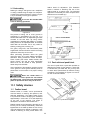
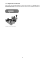
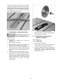
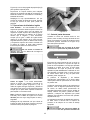
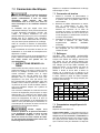
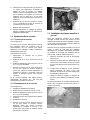
6.7 Motor cover
See Figure 6-7.
Slide pins of motor cover into hinge barrels on saw.
Close motor cover until it catches on post on saw.
Note: The catch mechanism may require
adjustment to ensure proper closure. Loosen screw
and position as needed. Retighten screw.
Figure 6-7: installing motor cover
6.8 Table insert
See Figure 6-8.
Place insert into table opening. Verify that insert
lies flush with table surface by resting a straight
edge across it at various points. If insert is not flush
along its length, turn any of 6 set screws to raise or
lower that area of insert.

12
Figure 6-8: leveling table insert
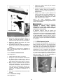
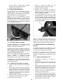
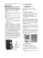
6.9 Installing and removing blade
Use caution when working
with or near sharp saw blades to prevent injury.
See Figure 6-9.
1. Disconnect machine from power source.
2. Remove table insert.
3. Raise blade arbor to highest position, and set
blade tilt to 0°.
4. Install blade onto arbor, making sure teeth
point downward toward front of saw.
5. Install flange and nut as shown.
6. Press down and hold lever (R, Figure 6-9), and
rotate blade until arbor lock engages. Tighten
nut clockwise with provided arbor wrench. Do
not overtighten nut.
Figure 6-9: installing blade
7. To remove blade, engage arbor lock and
remove nut with wrench.
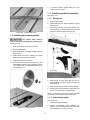
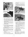
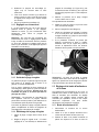
6.10 Installing guard/knife assembly
See Figure 6-10.
6.10.1 Riving knife
1. Remove table insert.
2. Raise blade arbor to highest position and set
blade tilt to 0°.
3. Pull clamp lever (S1, Figure 6-9) upward. The
clamp plate (S2) is spring loaded and will move
away from the fixed base, leaving a gap.
Figure 6-10: installing guard assembly
4. Slide prongs of riving knife (M) into slot on
clamping base, and push riving knife down as
far as it will go.
5. Push clamp lever (S1) down to closed position.
6. Riving knife must be parallel to saw blade. See
sect. 8.7 for inspection and adjustments.
NOTE: A low-profile riving knife is also provided,
for making non-through cuts on the table saw.
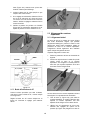
6.10.2 Anti-kickback pawls
See Figure 6-10.
1. Install insert plate into table.
2. Position anti-kickback pawl assembly (N,
Figure 6-10) so that angled side of pawl block
faces toward front of saw, as shown.

13
3. Lower pawl assembly onto center notch of
riving knife, with pawls straddling knife. Push
and hold button on pawl block (N1, Figure 6-
10), and push pawl block down until it securely
engages in notch.
4. Allow pawls to drop freely to table.
6.10.3 Blade guard
See Figure 6-10.
1. Push and hold button (K1) at back end of
guard.
2. Push guard (K) down at an angle, as shown,
until pin engages rear slot in riving knife, and
release button.
3. Push down front of guard until it seats
properly, and is parallel to table top. The
transparent guard leaves (K2) should drop
freely to the table.
NOTE: The transparent leaves can be kept in
raised position by swinging them up and forward.
Guard, riving knife, and pawl
assemblies must be securely installed, and
leaves must be in contact with table, before
beginning any through-cutting operation.
The riving knife clamping base is adjusted by the
manufacturer and no further adjustment of blade
guard and riving knife assembly should be
necessary. However, proper alignment is very
important. Before operating table saw, read sect.
8.7, Riving knife alignment, to verify and follow
adjustment procedure if necessary.
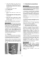
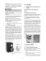
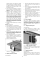
6.11 Dust port
Use of a dust collection system (not provided) is
strongly recommended during table saw operation.
It will help keep the shop clean, as well as prevent
potential health issues due to dust inhalation.
Make sure internal hose is pushed into external
dust port (Figure 6-11). Attach hose from your dust
collection system to the 4-inch dust port at base of
saw, and secure with wire hose clamp (not
provided).
Figure 6-11
7.0 Electrical connections
Electrical connections must be
made by a qualified electrician in compliance
with all relevant codes. This machine must be
properly grounded to help prevent electrical
shock and possible fatal injury.
A power plug is not provided with the PM3000B.
You may either connect the proper UL/CSA listed
plug or “hardwire” the machine directly to your
electrical panel provided there is a disconnect near
the machine for the operator. Consult electrical
drawings in sect. 15.0 for further clarification of
wiring setup.
Before connecting to power source, be sure switch
is in off position.
It is recommended that the PM3000B table saw be
connected to a dedicated 30 amp circuit with
breaker or fuse.
If connected to a circuit protected by fuse, use time
delay fuse marked “D”. Local codes take
precedence over recommendations.
7.1 GROUNDING INSTRUCTIONS
This machine must be grounded. In the event of a
malfunction or breakdown, grounding provides a
path of least resistance for electric current to
reduce the risk of electric shock. This tool is
equipped with an electric cord having an
equipment-grounding conductor. A plug is not
provided. A proper UL/CSA listed plug may be
installed or the machine may be “hard-wired” to a
circuit panel. If hard-wired, make sure a disconnect
is available to the operator.
Improper connection of the equipment-grounding
conductor can result in a risk of electric shock. The
conductor with insulation having an outer surface
that is green with or without yellow stripes is the
equipment-grounding conductor. If repair or
replacement of the electric cord or a plug is
necessary, do not connect the equipment-
grounding conductor to a live terminal.
Check with a qualified
electrician or service personnel if the
grounding instructions are not completely
understood, or if in doubt as to whether the
tool is properly grounded. Failure to comply
may cause serious or fatal injury.
Repair or replace damaged or worn cord
immediately.

14
7.2 Voltage conversion
1. Remove transformer cover at back of machine,
and move fuse from 230V position to 460V
position on transformer.
2. Switch the incoming power leads to the motor
for 460 volt operation, according to wiring
diagram on inside cover of motor junction box.
A similar diagram is found in sect. 15.0 of this
manual. (In case of discrepancy, diagram in
junction box takes precedence.)
3. Replace the 230V overload relay with a 460V
overload relay (additional purchase, part
number PM3000B-2107AOR).
4. If using a plug, the 230V plug must be
replaced with a UL/CSA listed plug rated for
460V.
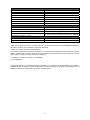
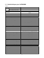
7.3 Extension cords
USE PROPER EXTENSION CORD. Make sure
your extension cord is in good condition. When
using an extension cord, be sure to use one heavy
enough to carry the current your product will draw.
An undersized cord will cause a drop in line voltage
resulting in loss of power and overheating. Table 3
shows correct size to use depending on cord
length and nameplate ampere rating. If in doubt,
use the next heavier gauge. The smaller the gauge
number, the heavier the cord.
Amp Rating Volts Total length of cord (ft.)
More
Than
Not
More
Than
240 50 100 200 300
AWG
0 6 18 16 16 14
6 10 18 16 14 12
10 12 16 16 14 12
12 16 14 12 Not
Recommended
Table 2: extension cord recommendations
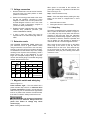
7.4 Magnetic switch and safety key
Refer to Figure 7-2.
Power Indicator Light – The start switch has a
power indicator lamp which is on whenever there
is power connected to the saw, not just when the
saw is running. Do not assume that no light means
there is no power to the machine. If the bulb is bad,
there will no indication. Always check before use.
Do not rely that no light means
no power to the machine. Always check for
power first. Failure to comply may cause
serious injury.
Start – Press green start switch.
When power is connected to the machine, the
green light is always on regardless of whether the
saw is running or not.
Stop – Press red switch to stop.
Reset – If the saw stops without pressing the stop
button, as the result of a tripped fuse or circuit
breaker:
1. Press red button to reset.
2. Press green button to restart machine.
7.4.1 Safety Key
The switch is equipped with a magnetic safety key.
When in place on the switch as shown in Figure 7-
2, the safety key trips a relay which will allow the
machine to start and stop when the respective
switches are pressed. Being magnetic, the key can
be removed to make the machine inoperable and
can be hidden for safe storage by attaching it
underneath the rail or another magnetic surface.
When using the saw, place the key on the switch
cover lining up the arrow on the key with the
REMOVE arrow on the cover. Then rotate the key
so the arrow lines up with the LOCK arrow. This
prevents the safety key from vibrating loose when
machine is in use.
Figure 7-2

15
8.0 Adjustments
8.1 Tools required for adjustments
Hex keys: 2.5mm, 3mm, 4mm
Wrenches: 13mm, 19mm, 22mm (or adjustable)
Straight edge
Square
8.2 Fence alignment
Before using the Accu-Fence®, verify that it is
properly aligned with the blade. Consult manual no.
M-2195079B that accompanied the fence.
8.3 Blade raising and tilting
See Figure 8-1.
To raise or lower blade, loosen lock knob (A,
Figure 8-1) and turn handwheel (B) on front of saw
until desired height is reached. Tighten lock knob
(A). The blade should be raised about 1/8" above
top surface of material being cut.
To tilt blade, loosen lock knob (C) and turn
handwheel (D) until desired angle is obtained, as
shown on tilt scale. Retighten lock knob (C).
Reference pointers (E) can be positioned at any
point along scale; loosen knob and slide pointer to
position, then tighten knob. These provide a quick
reference point for aligning the angle indicator.
Figure 8-1
8.4 Miter gauge
Refer to Figures 8-2 and 8-3.
8.4.1 Setting miter angle
The miter gauge has rack and pinion adjustment
for setting angle. To operate:
1. Slide miter gauge into table slot.
2. Loosen lock handle (H, Figure 8-2) by turning
counterclockwise.
3. Pull out spring-loaded knob (J) and rotate knob
until body (K) of miter gauge is at desired
angle as indicated on scale.
4. Tighten lock handle (H).
8.4.2 Indent settings
There are indents at 0º, 30º and 45º right and left
positions. At these settings, release knob (J) to
engage indent. Then tighten lock handle (H).
Note: Do not rely solely on the indents for an
accurate setting. After stop rod engages at the 0º,
30º and 45º positions, make a fine adjustment with
the knob (J) if necessary, setting it against the
scale indicator (L).
Figure 8-2
8.4.3 Miter gauge fence
The miter gauge fence (M, Figure 8-2) can be
adjusted by sliding to right or left, or removed
entirely.
To adjust, loosen two lock handles (N), slide fence
and retighten lock handles. Make sure end of
fence is not in blade path.
NOTE: The lock handles (N) are adjustable. Pull
out on handle, rotate it to different position, then
release, making sure it seats itself upon the pin.
To remove miter gauge fence, slide it completely
off and remove lock handles (N) and mounting
hardware.
8.4.4 Miter gauge calibration
1. Place miter gauge into table slot.
2. Set miter gauge at 90º to blade (0º setting on
scale) by loosening lock handle (H, Figure 8-
2), then pulling out spring-loaded knob (J) and
turning body (K) until 0º is indicated on scale.
3. Measure accuracy of miter gauge against slot
with a square.
If adjustment is needed:
4. Adjust body (K) until it is square (90º) to miter
slot.
5. Tighten lock handle (H).
6. Verify that scale indicator (L) reads 0º. If it
does not, loosen screw (P) and adjust
indicator (L) until it reads 0º. Retighten screw
(P).

16
7. If the above procedure does not satisfactorily
align the miter gauge, loosen two screws (R,
Figure 8-3) beneath mounting block and shift
block as needed. Retighten screws when
finished.
Figure 8-3
NOTE: The miter gauge bar has two slots with set
screws (S, Figure 8-2). Adjust these set screws to
eliminate any play between bar and miter slot.
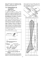
8.5 Blade tilt stop adjustment
The stops for 90°, 45° blade tilt, and elevation
settings have all been factory set, and should
require no immediate adjustment. The settings
should be confirmed by the operator, however, and
especially if cuts become inaccurate. Both tilt stops
are located on the trunnion.
8.5.1 Tilt stop 90°
1. Disconnect machine from power source.
2. Make sure table insert has been leveled with
table surface (sect. 6.8).
3. Raise blade to highest position, and place a
square on table and against blade (Figure 8-
4). Make sure that a blade tooth does not
obstruct the actual reading.
4. Tilt blade with handwheel until square and
blade are flush.
5. If adjustment is required, loosen nut on 90°
stop screw (Figure 8-5) with 13mm wrench,
and turn screw to proper height. Verify setting
and retighten nut against trunnion.
6. Check pointer position on scale (Figure 8-5). If
needed, loosen screw and adjust pointer to
zero. Retighten screw.
Figure 8-4
Figure 8-5
8.5.2 Tilt stop 45°
Follow same procedure as above, but with blade
tilted at 45°, as shown in Figure 8-6.
Adjust 45° stop shown in Figure 8-5. Confirm
setting, then retighten nut.
Figure 8-6

17
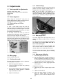
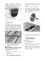
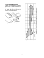
8.6 Riving knife alignment
8.6.1 Lateral alignment
Saw blade and riving knife must be as closely
aligned as possible (lateral alignment) for
prevention of kickback. This should be checked
upon initial blade guard and riving knife installation.
Alignment should also be reaffirmed after each
blade change.
Inspect alignment as follows:
1. Remove blade guard and pawl assembly.
2. Place a straightedge on table so it rests
against blade and riving knife. See Figure 8-7.
Rotate blade so that top of blade tooth touches
straightedge.
Figure 8-7
The saw blade and riving knife must be in line. If
adjustment is needed:
3. Pull up lever (A, Figure 8-8) and remove riving
knife, making note as to which direction riving
knife needs to be moved to align it with saw
blade.
4. Use 3mm hex key to make adjustments to four
set screws (B, Figure 8-8). Adjust any of the
set screws required to bring riving knife in
alignment with saw blade.
5. Reinsert riving knife, secure by tightening lever
(A) and check alignment per step 2.
6. Repeat steps 3–5 until alignment is correct.
8.6.2 Blade proximity alignment
The gap between saw blade and riving knife must
be between 3mm (0.12in.) and 8mm (0.32in.). See
Figure 8-9.
If adjustment is needed, note whether blade-to-
knife gap needs to be increased or decreased.
Then adjust as follows:
Figure 8-8
Figure 8-9
7. Remove blade guard, pawl assembly, table
insert and riving knife.
8. Use 3mm hex key to loosen two socket head
button screws (C, Figure 8-8). This will allow
the clamp plate (D) to slide back and forth on
the fixed base.
Slide clamp plate (D) toward or away from saw
blade as required. Attempt to make the gaps
as even as possible.
9. Tighten screws (C).
10. Reinsert riving knife; engage lever (A) and
check that saw blade/knife gap is between
3-8mm (Figure 8-9).
8.7 Table to blade alignment
See Figures 8-10 and 8-11.
The table has been squared to the blade by the
manufacturer and no adjustment should be needed
now. If cuts become inaccurate, check table/blade
squareness and correct if necessary.
1. Disconnect saw from power source.
2. Raise blade to maximum height.
3. Mark one tooth (A, Figure 8-10) with a grease
pencil and position the tooth slightly above top
edge of table at the front.

18
4. Raise miter gauge slightly out of its slot to
serve as a shoulder. Using a sliding square (B)
against the side of the bar, slide the scale over
until it touches the tip of the blade, and lock
scale in position.
Figure 8-10
Figure 8-11
5. Rotate marked tooth (A) so that it is slightly
above table top at the rear, using the square
as before to verify that distance to blade is
identical. See Figure 8-11. If the two distances
are not the same, make a careful note of the
difference.
6. Loosen table screws (item #23, sect. 14.1.1),
and nudge table according to the distance you
noted.
7. Retighten screws firmly.
8. Verify alignment, angle pointer setting, fence
setting, etc. Make any needed adjustments.
8.8 Belt adjustment
8.8.1 Belt tension
See Figure 8-12.
Drive belt tension should be inspected after the first
few days of operation, as a belt may stretch slightly
during initial use; also inspect it periodically
thereafter.
To tighten belt:
1. Disconnect machine from power source.
2. Loosen screw (C, Figure 8-12) with 17mm
wrench.
3. Slightly loosen nut (D) with 1-1/4” (or
adjustable) wrench.
4. Push motor to the right and tighten screw (C)
to tension belt. Retighten nut (D). Verify proper
tension by pushing on belt midway between
pulleys; deflection should be about 1/2-inch.
If belt shows signs of wear, fraying, cracks, etc. it
should be replaced, as follows.
8.8.2 Belt replacement
See Figure 8-12.
1. Lower trunnion completely.
2. Loosen screw (C) with 17mm wrench.
3. Slightly loosen nut (D) with 1-1/4” (or
adjustable) wrench.
4. Pivot motor to the left to release tension.
5. Replace belt.
6. Push motor to the right and tighten screw (C)
to tension new belt. Retighten nut (D). Verify
proper tension by pushing on belt midway
between pulleys; deflection should be about
1/2-inch.
Figure 8-12
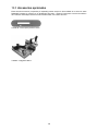
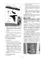
8.9 Zero-clearance insert setup
Under normal operations where the standard table
insert (provided) is used, the top edge of saw blade
will come to rest approximately 1/8" below table
surface when blade is at lowest position.
In situations where a zero-clearance insert is
desired, the saw blade may be lowered further for
accommodation of inserts that have potential
clearance issues with the blade. This is done as
follows:
1. Remove blade guard and pawls (Figure 6-10).
2. Open side cover and locate blade depth stop
screw (A, Figure 8-13) located between arbor
pulley and motor.

19
3. Using a 14mm open wrench, loosen hex nut
(B, Figure 8-13). This will allow hex cap screw
to be turned and saw blade to be adjusted
lower.
4. Use height adjust handwheel (B, Figure 8-1),
to lower saw blade all the way.
The zero-clearance insert can now be placed in
table opening without contacting blade.
Figure 8-13
Never use a zero-clearance
insert with saw blade in tilted position. Never
operate saw without blade guard, riving knife
and anti-kickback pawls for operations where
they can be used.
When the standard insert is to be used again, the
saw blade must be readjusted as follows:
5. With the height adjust handwheel (B, Figure 8-
1), adjust blade height until top of saw blade is
1/8" below top of table.
6. The blade depth stop screw (A, Figure 8-13)
should be resting against the trunnion. Verify
this; then tighten hex nut (B, Figure 8-13).
7. Reinstall standard insert, pawls and blade
guard.
9.0 Operations
Familiarize yourself with the location and operation
of all controls and adjustments and the use of
accessories such as miter gauge and rip fence.
Note: The following figures are general in nature
and may not show your particular saw model.
9.1 Kickback prevention
Serious injury can result from kickbacks which
occur when a workpiece binds on the saw blade or
binds between the blade and rip fence or other
fixed object. This binding can cause the workpiece
to lift up and be thrown toward the operator.
Listed below are conditions which can cause
kickbacks:
Confining the cutoff piece when crosscutting
or ripping.
Releasing workpiece before completing
operation or not pushing workpiece all the
way past saw blade.
Not using splitter/riving knife when ripping or
not maintaining alignment of splitter/ riving
knife with saw blade.
Using dull saw blade.
Not maintaining alignment of rip fence so that
it tends to angle toward rather than away
from saw blade front to back.
Applying feed force when ripping to the cutoff
(free) section of workpiece instead of the
section between saw blade and fence.
Ripping wood that is twisted (not flat), or
does not have a straight edge, or has twisted
grain.
To minimize or prevent injury from kickbacks:
Avoid conditions listed above.
Wear a safety face shield, goggles, or safety
glasses.
Do not use miter gauge and rip fence in the
same operation unless provision is made by
use of a facing board on the fence, to allow
the cutoff section of workpiece to come free
before the actual cut begins (See Figure 9-
8).
As the machine receives use, the operation
of the anti-kickback pawls should be checked
periodically (Figure 9-1). If the pawls do not
stop the reverse motion of a workpiece,
resharpen all the points.
Where possible, keep your face and body out
of line with potential kickbacks, including
when starting or stopping the machine.
Dull, badly set, improper, or improperly filed
cutting tools, and cutting tools with gum or
resin adhering to them can cause accidents.
Never use a cracked saw blade. The use of a
sharp, well maintained, and correct cutting
tool for the operation will help avoid injuries.
Figure 9-1

20
Support the work properly and hold it firmly
against gauge or fence. Use a push stick or
push block when ripping short, narrow (6"
width or less), or thin work. Use a push block
or miter gauge hold-down when dadoing or
molding.
Never use the fence as a length stop when
crosscutting. Do not hold or touch the free
end or cutoff section of a workpiece. On
through-sawing operations, the cutoff section
must NOT be confined.
Always keep your hands out of line of the
saw blade and never reach back of the
cutting blade with either hand to hold the
workpiece.
Bevel ripping cuts should always be made
with the fence on the right side of saw blade
so that the blade tilts away from the fence
and minimizes possibility of the work binding
and the resulting kickback.
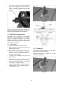
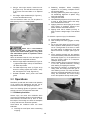
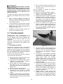
9.2 Rip sawing
Ripping is feeding the workpiece with the grain into
the saw blade using the fence or other positioning
device as a guide to ensure desired width of cut
(Figure 9-2).
Before starting a rip cut, verify
that fence is clamped securely and aligned
properly.
Never rip freehand or use miter gauge in
combination with the fence.
Never rip workpieces shorter than the saw
blade diameter.
Never reach behind the blade with either
hand to hold down or remove the cutoff piece
with the saw blade rotating.
Figure 9-2
Always use blade guard, splitter/riving knife and
anti-kickback pawls. Make sure splitter/riving knife
is properly aligned. When wood is cut along the
grain, the kerf tends to close and bind on the blade
and kickbacks can occur.
Note: A warning decal is affixed to the guard to
remind the operator of some basic safety
procedures.
The rip fence should be set for the width of the cut
by using the scale on the front rail, or by measuring
the distance between blade (A) and fence (B).
Stand out of line with saw blade and workpiece to
avoid sawdust and splinters coming off the blade or
a potential kickback.
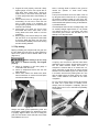
If the workpiece does not have a straight edge, nail
an auxiliary straight edged board on it to provide
one against the fence. To cut properly, the board
must make good contact with the table. Do not
attempt to cut warped boards.
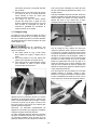
Figure 9-3
In ripping, use one hand to hold the board down
against the fence or fixture, and the other to push it
into the blade between blade and fence. If
workpiece is narrower than 6" or shorter than 12",
use a push stick or push block to push it through
between fence and blade (Figure 9-4). Never push
in a location such that the pushing hand is in line
with the blade. Move the hand serving as a hold-
down a safe distance from blade as cut nears
completion.
For very narrow ripping where a push stick cannot
be used, use a push block or auxiliary fence.
Always push the workpiece completely past the
blade at the end of a cut to minimize the possibility
of a kickback.
Figure 9-4
La page est en cours de chargement...
La page est en cours de chargement...
La page est en cours de chargement...
La page est en cours de chargement...
La page est en cours de chargement...
La page est en cours de chargement...
La page est en cours de chargement...
La page est en cours de chargement...
La page est en cours de chargement...
La page est en cours de chargement...
La page est en cours de chargement...
La page est en cours de chargement...
La page est en cours de chargement...
La page est en cours de chargement...
La page est en cours de chargement...
La page est en cours de chargement...
La page est en cours de chargement...
La page est en cours de chargement...
La page est en cours de chargement...
La page est en cours de chargement...
La page est en cours de chargement...
La page est en cours de chargement...
La page est en cours de chargement...
La page est en cours de chargement...
La page est en cours de chargement...
La page est en cours de chargement...
La page est en cours de chargement...
La page est en cours de chargement...
La page est en cours de chargement...
La page est en cours de chargement...
La page est en cours de chargement...
La page est en cours de chargement...
La page est en cours de chargement...
La page est en cours de chargement...
La page est en cours de chargement...
La page est en cours de chargement...
La page est en cours de chargement...
La page est en cours de chargement...
La page est en cours de chargement...
La page est en cours de chargement...
La page est en cours de chargement...
La page est en cours de chargement...
La page est en cours de chargement...
La page est en cours de chargement...
La page est en cours de chargement...
La page est en cours de chargement...
La page est en cours de chargement...
La page est en cours de chargement...
La page est en cours de chargement...
La page est en cours de chargement...
La page est en cours de chargement...
La page est en cours de chargement...
La page est en cours de chargement...
La page est en cours de chargement...
La page est en cours de chargement...
La page est en cours de chargement...
La page est en cours de chargement...
La page est en cours de chargement...
La page est en cours de chargement...
La page est en cours de chargement...
La page est en cours de chargement...
La page est en cours de chargement...
La page est en cours de chargement...
La page est en cours de chargement...
La page est en cours de chargement...
La page est en cours de chargement...
La page est en cours de chargement...
La page est en cours de chargement...
La page est en cours de chargement...
La page est en cours de chargement...
La page est en cours de chargement...
La page est en cours de chargement...
La page est en cours de chargement...
La page est en cours de chargement...
La page est en cours de chargement...
La page est en cours de chargement...
La page est en cours de chargement...
La page est en cours de chargement...
La page est en cours de chargement...
La page est en cours de chargement...
La page est en cours de chargement...
La page est en cours de chargement...
La page est en cours de chargement...
La page est en cours de chargement...
La page est en cours de chargement...
La page est en cours de chargement...
La page est en cours de chargement...
La page est en cours de chargement...
La page est en cours de chargement...
La page est en cours de chargement...
La page est en cours de chargement...
La page est en cours de chargement...
La page est en cours de chargement...
La page est en cours de chargement...
La page est en cours de chargement...
La page est en cours de chargement...
La page est en cours de chargement...
La page est en cours de chargement...
La page est en cours de chargement...
La page est en cours de chargement...
La page est en cours de chargement...
La page est en cours de chargement...
La page est en cours de chargement...
La page est en cours de chargement...
La page est en cours de chargement...
La page est en cours de chargement...
La page est en cours de chargement...
La page est en cours de chargement...
La page est en cours de chargement...
La page est en cours de chargement...
La page est en cours de chargement...
La page est en cours de chargement...
-
 1
1
-
 2
2
-
 3
3
-
 4
4
-
 5
5
-
 6
6
-
 7
7
-
 8
8
-
 9
9
-
 10
10
-
 11
11
-
 12
12
-
 13
13
-
 14
14
-
 15
15
-
 16
16
-
 17
17
-
 18
18
-
 19
19
-
 20
20
-
 21
21
-
 22
22
-
 23
23
-
 24
24
-
 25
25
-
 26
26
-
 27
27
-
 28
28
-
 29
29
-
 30
30
-
 31
31
-
 32
32
-
 33
33
-
 34
34
-
 35
35
-
 36
36
-
 37
37
-
 38
38
-
 39
39
-
 40
40
-
 41
41
-
 42
42
-
 43
43
-
 44
44
-
 45
45
-
 46
46
-
 47
47
-
 48
48
-
 49
49
-
 50
50
-
 51
51
-
 52
52
-
 53
53
-
 54
54
-
 55
55
-
 56
56
-
 57
57
-
 58
58
-
 59
59
-
 60
60
-
 61
61
-
 62
62
-
 63
63
-
 64
64
-
 65
65
-
 66
66
-
 67
67
-
 68
68
-
 69
69
-
 70
70
-
 71
71
-
 72
72
-
 73
73
-
 74
74
-
 75
75
-
 76
76
-
 77
77
-
 78
78
-
 79
79
-
 80
80
-
 81
81
-
 82
82
-
 83
83
-
 84
84
-
 85
85
-
 86
86
-
 87
87
-
 88
88
-
 89
89
-
 90
90
-
 91
91
-
 92
92
-
 93
93
-
 94
94
-
 95
95
-
 96
96
-
 97
97
-
 98
98
-
 99
99
-
 100
100
-
 101
101
-
 102
102
-
 103
103
-
 104
104
-
 105
105
-
 106
106
-
 107
107
-
 108
108
-
 109
109
-
 110
110
-
 111
111
-
 112
112
-
 113
113
-
 114
114
-
 115
115
-
 116
116
-
 117
117
-
 118
118
-
 119
119
-
 120
120
-
 121
121
-
 122
122
-
 123
123
-
 124
124
-
 125
125
-
 126
126
-
 127
127
-
 128
128
-
 129
129
-
 130
130
-
 131
131
-
 132
132


Powermatic 3000B table saw - 7.5HP 3PH 230/460v 50" RIP Manuel utilisateur
- Taper
- Manuel utilisateur
- Ce manuel convient également à
dans d''autres langues
Documents connexes
Autres documents
-
Delta 36-L552D Manuel utilisateur
-
-
Delta 36-5000 Le manuel du propriétaire
-
-
Delta 36-5000T2 Manuel utilisateur
-
-
Ryobi RTS11 Le manuel du propriétaire
-
DeWalt DWE7480 Manuel utilisateur
-
Wyndham Collection WC-4141-84-DBL Guide d'installation
-
Wyndham Collection WC-4141-60-DBL Guide d'installation