Tripp Lite BP Series External Battery Packs Le manuel du propriétaire
- Taper
- Le manuel du propriétaire

1
Owner’s Manual
BP Series
External Battery Packs
Not suitable for mobile applications.
Introduction 2
Important Safety Instructions 2
Mounting 4
Connection 11
Maintenance 12
Warranty and Product Registration 13
Español 14
Français 27
Русский
40
1111 W. 35th Street, Chicago, IL 60609 USA • www.tripplite.com/support
Copyright © 2018 Tripp Lite. All rights reserved.
PROTECT YOUR INVESTMENT!
Register your product for quicker service and ultimate peace of mind.
You could also win an ISOBAR6ULTRA surge protector—a $100 value!
www.tripplite.com/warranty
24V Battery Packs 36V Battery Packs 48V Battery Packs 72V Battery Packs
BP24V15RT2U, 14AH
BP24V28-2U, 28AH
BP24V36-2US, 36AH
BP24V70-3U, 70AH
BP36V15-2U, 18AH
BP36V42-3U, 21AH
BP48V24-2U, 18AH
BP48V27-2US, 27AH
BP48V60RT-3U, 42AH
BP72V15-2U, 15AH
BP72V18-2US, 18AH
BP72V28RT-3U, 28AH
18-09-336 93-36FF.indb 1 12/18/2018 8:26:57 AM

2
Introduction
Important Safety Instructions
Tripp Lite BP Series External Battery Packs are designed for use with various Tripp Lite
UPS systems equipped with external battery pack connectors.
SAVE THESE INSTRUCTIONS
WARNING! The mounting shelves are not intended to support more than
one battery pack. Do not stack multiple battery packs on a single set of
mounting shelves. Failure to follow this warning may lead to product
damage and/or risk of personal bodily harm.
• Use caution when lifting battery packs. Because of the considerable weight of
all battery packs, at least two people should assist in lifting and installing
them.
• Make certain the battery packs and UPS use the same DC voltage before
connecting them.
• Use only Tripp Lite external battery packs with overcurrent protection.
Installation is by qualified service personnel only. Contact Tripp Lite Customer
Support at 773.869.1234 for the appropriate Tripp Lite battery pack to
connect.
• Your external metal battery cabinets are provided with a means for
equipotential protective bonding for safety. When using 2-pin connector
external batteries, be sure to bond the metal enclosure of your external
battery to the metal enclosure of the UPS system. Three-pin/conductor battery
packs are equipped with a ground bond plug. Plastic enclosures do not require
bonding. See below for ground bonding strap requirements:
24V Battery Packs
BP24V15RT2U: Plastic enclosure, so ground bonding strap is not required.
BP24V28-2U: 12 AWG ground bonding strap
BP24V36-2US: 12 AWG ground bonding strap
BP24V70-3U: 12 AWG ground bonding strap
36V Battery Packs
BP36V15-2U: 12 AWG ground bonding strap
BP36V42-3U: 12 AWG ground bonding strap
48V Battery Packs
BP48V24-2U: 12 AWG ground bonding strap
BP48V27-2US: 12 AWG ground bonding strap
BP48V60RT-3U: 12 AWG ground bonding strap
Note: The battery connector on 72V battery packs has a built-in ground bonding plug, so an
additional ground bonding strap isn’t needed.
18-09-336 93-36FF.indb 2 12/18/2018 8:26:57 AM

3
Important Safety Instructions
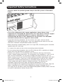
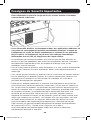
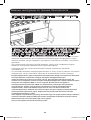
Securely attach the provided ground strap to the UPS system as illustrated
below:
• Use of this equipment in life support applications where failure of this
equipment can reasonably be expected to cause the failure of the life support
equipment or to significantly affect its safety or effectiveness is not
recommended. Do not use this equipment in the presence of a flammable
anesthetic mixture with air, oxygen or nitrous oxide.
• Suggested mounting procedures are for common rack types and may not be
appropriate for all rack configurations. User must determine the fitness of rack and
wall-mount hardware and procedures before mounting.
• When connecting multiple battery packs to a single UPS, the battery packs should be
approximately the same age.
• It is normal for sparks to occur when connecting external batteries.
• Do not unplug external batteries from the UPS while the UPS is operating on battery
power, due to the possibility of dangerous arcing.
• Batteries can present a risk of electrical shock and burn from high short-circuit
current. Observe proper precautions. Do not dispose of the batteries in a fire. Do not
open the UPS or batteries. Do not short or bridge the battery terminals with any
object. Unplug and turn off the UPS before performing battery replacement. Use tools
with insulated handles. There are no user-serviceable parts inside the UPS. Battery
replacement should be performed only by authorized service personnel using the
same number and type of batteries (Sealed Lead-Acid). The batteries are
recyclable. Refer to your local codes for disposal requirements or visit
http://www.tripplite.com/support/recycling-program for recycling information. Tripp Lite
offers a complete line of UPS System Replacement Battery Cartridges (R.B.C.).
Visit Tripp Lite on the Web at http://www.tripplite.com/products/battery-finder/ to locate
the specific replacement battery for your UPS.
18-09-336 93-36FF.indb 3 12/18/2018 8:26:57 AM

4
Mounting (Rack)
Mount your rackmount battery pack in either a 4-post or 2-post rack or rack enclosure
(see page 6 for 2-post mounting). The user must determine the fitness of hardware and
procedures before mounting. If hardware and procedures are not suitable for your
application, contact the manufacturer of your rack or rack enclosure. The procedures
described in this manual are for common rack and rack enclosure types and may not be
appropriate for all applications.
4-Post Mounting
Most external battery packs include the hardware required for 4-post mounting. If this
hardware did not come with your unit, an Adjustable 4-Post Rackmount Shelf Kit
(Model 4POSTRAILKIT) may be ordered separately.
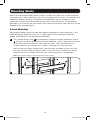
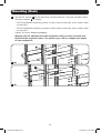
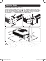
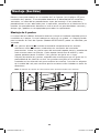
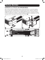
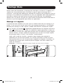
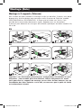
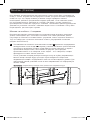
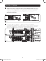
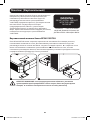
1
The included plastic pegs
A
will temporarily support the empty rackmount shelves
B
while you install the permanent mounting hardware. Insert a peg near the center
of the front and rear bracket of each shelf as shown. (Each front bracket has
6 holes and each rear bracket has 3 holes.) The pegs will snap into place.
After installing the pegs, expand each shelf to match the depth of your rack rails.
The pegs will fit through the square holes in the rack rails to support the shelves.
Refer to the rack unit labels to confirm the shelves are level in all directions.
Note: The support ledge of each shelf must face inward.
B
B
1
A
A
A
A
18-09-336 93-36FF.indb 4 12/18/2018 8:26:57 AM

5
Mounting (Rack)
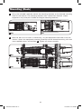
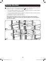
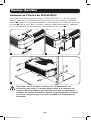
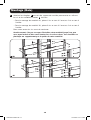
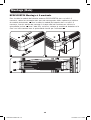
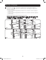
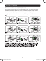
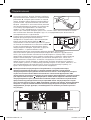
2U
3U
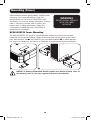
2
Secure the shelves
B
to the mounting rails permanently using the included screws
and cup washers
C
as shown.
• For 2U equipment mounting, place 4 screws total at the front and 4 screws total
at the back.
• For 3U equipment mounting, place 6 screws total at the front and 4 screws total
at the back.
Tighten all screws before proceeding.
Warning: Do not attempt to install equipment until you have inserted and
tightened the required screws. The plastic pegs will not support the weight
of your equipment.
2
2
C
C
C
C
B
B
18-09-336 93-36FF.indb 5 12/18/2018 8:26:58 AM

6
Mounting (Rack)
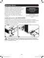
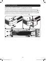
3U2U
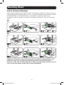
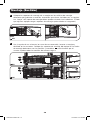
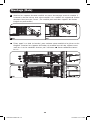
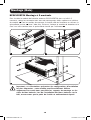
3
Using the included hardware, attach the mounting brackets to the forward mounting
holes of the cabinet. The mounting bracket "ears" should face forward. (Some
equipment may have pre-installed or integral mounting brackets.)
3
4
With the aid of an assistant (if necessary), lift your equipment and slide it into the
shelves. Attach the equipment mounting brackets to the forward mounting rails with
user-supplied screws and washers
D
. Tighten all screws securely.
3U
2U
4
4
D
D
D
D
18-09-336 93-36FF.indb 6 12/18/2018 8:27:00 AM

7
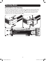
2-Post (Telecom) Mounting
Select external battery pack models include the hardware required for 2-post mounting.
If this hardware did not come with your unit, a 2-Post Rackmount Installation Kit (Model
2POSTRMKITWM or 2POSTRMKITHD) may be ordered separately. Refer to the
illustrations below for specific installation instructions covering 2U, 3U and 4U battery
packs.
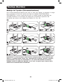
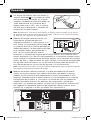
Important: Illustrations show the most typical installation configurations; your
model may vary. Use only the pre-drilled screw holes to attach mounting
brackets to the sides of the battery pack. When installing battery packs into the
rack, ensure the weight of the unit is evenly distributed.
2U
1
X 8
2U
2
X 4
3
X 2 X 2 X 2
3U
3U
4U
4U
X 8
X 4
X 4
X 4
Mounting (Rack)
X 8
X 4
1
1
2
2
3
3
18-09-336 93-36FF.indb 7 12/18/2018 8:27:02 AM

8
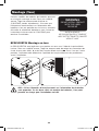
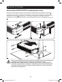
BP24V15RT2U 4-Post Mounting
To install an external battery pack in a 4-post rack, remove the mounting hole covers
from the top and bottom sides of the battery pack
1
. To install the battery pack in a
4-post rack, attach the mounting ears to each side of the UPS using the included
hardware
2
. With the help of an assistant, lift the battery pack and attach it to a
standard rack with user-supplied hardware
3
.
Mounting (Rack)
3
1 2
18-09-336 93-36FF.indb 8 12/18/2018 8:27:03 AM

9
BP24V15RT2U 2-Post Mounting
To install the external battery pack in a 2-post rack, remove the mounting hole covers
from the top and bottom sides of the pack
1
. Attach the mounting ears to each side of
the UPS using the included hardware
2
. With the help of an assistant, lift the battery
pack and attach it to a standard rack with user-supplied hardware
3
.
Mounting (Rack)
3
1 2
Important: Illustrations show the most common installation
configurations; your model may vary. Use only the pre-drilled screw holes
to attach mounting brackets to the sides of the battery pack. When
installing battery packs into the rack, ensure the weight of the unit is
evenly distributed.
18-09-336 93-36FF.indb 9 12/18/2018 8:27:03 AM

10
Select external battery pack models support tower
mounting. For increased stability, Tripp Lite
recommends the use of the 2-9USTAND (sold
separately). Ensure the Battery Orientation Warning
label is not facing upward when installing the
battery pack in tower orientation. Follow the
instructions included with the 2-9USTAND to
complete the installation.
Mounting (Tower)
WARNING
DO NOT INSTALL PRODUCT
WITH THIS LABEL
FACING UP
BP24V15RT2U Tower Mounting
The BP24V15RT2U will stand in a tower position without the aid of the included
hardware. For increased stability, Tripp Lite recommends removing the screw covers
from each bottom side
1
and attaching the included hardware
2
. In either position,
the user must determine the fitness of hardware and procedures before installation.
1 2
NOTICE: If Battery Orientation Warning labels are affixed to both sides of
the battery pack, it can only support rack-mount installation.
18-09-336 93-36FF.indb 10 12/18/2018 8:27:04 AM

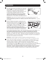
11
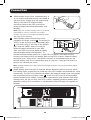
1
Select battery packs have a polarized plug
A
on an output cord permanently connected to
the rear panel. Simply plug the output cord
directly into the UPS external battery
connector (refer to the UPS manual for
external battery connector description and
location).
Note: Only one of these battery packs is generally
connected to a UPS at one time. For longer
runtime, use one or more Tripp Lite Battery Packs
with daisy-chain capability.
2
Select battery packs feature daisy-chain
capability for longer runtime
B
. To connect to
a UPS, insert one end of the attached cable
C
into either plug on the rear of the battery
pack and the cable’s other end into the
external battery connector of your UPS.
(See your UPS manual for external battery
connector description and location.) To
Connection
A
B
C
1
2
3
connect multiple battery packs to a single UPS for greatly increased runtime,
connect the output of the first battery pack to the UPS system's external battery
connector, then “daisy-chain” the others: connect an input/output plug on the
second battery pack to an input/output plug on the first, a plug on the third to a
plug on the second and so on.
Note: Multiple battery pack arrays will provide longer runtimes, but will also require longer
recharge times.
3
Select battery packs contain an external battery detection port on the rear panel.
The battery packs should only be used with host UPS models that provide the same
functionality. The UPS will automatically detect the external battery upon connection
with the battery communication cable
D
. Check the UPS manual for compatible
external battery pack models, configuration requirements and potential limitations.
Battery packs are for use only with UPS systems supporting external battery pack
detection cabling (this connection is not required if the UPS does not support this
feature).
D
Battery
Pack
UPS
18-09-336 93-36FF.indb 11 12/18/2018 8:27:05 AM

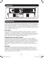
12
Maintenance
Battery packs require no maintenance but should be kept dry at all times. Avoid
installation in locations with high heat and/or humidity. The battery packs should be kept
fully charged by being connected to an active UPS system, not left in a depleted
condition. Batteries left in a discharged state will suffer a permanent loss of capacity.
Troubleshooting
There is a fuse array inside the battery packs. If a heavy overload or short circuit is
encountered, a fuse will open (blow). A battery pack with a blown fuse will deliver no
output voltage at any load. A qualified technician must replace the fuses. Contact
Tripp Lite Customer Support for additional information.
Internal Battery Replacement
The batteries in the battery packs will eventually wear out and be unable to provide
adequate backup times. The batteries should only be replaced by factory authorized
service personnel. Tripp Lite offers an exchange program for North American customers
wherein they may exchange worn-out battery packs for new ones at a price comparable
to the cost of individual battery replacement. For more details, visit
www.tripplite.com/support.
Storage
Disconnect your battery pack’s power cable before storing. If you plan to store your
battery pack for an extended period of time, fully recharge its batteries every three
months by connecting it to a UPS that is connected to AC input for at least 12 hours.
Service
Your Tripp Lite product is covered by the warranty described in this manual. A variety of
Extended Warranty and On-Site Service Programs are also available from Tripp Lite. For
more information on service, visit www.tripplite.com/support. Before returning your
product for service, follow these steps:
1. Review the installation and operation procedures in this manual to insure that the
service problem does not originate from a misreading of the instructions.
2. If the problem continues, do not contact or return the product to the dealer. Instead,
visit www.tripplite.com/support.
3. If the problem requires service, visit www.tripplite.com/support and click the Product
Returns link. From here you can request a Returned Material Authorization (RMA)
number, which is required for service. This simple on-line form will ask for your unit’s
model and serial numbers, along with other general purchaser information. The RMA
number, along with shipping instructions will be emailed to you. Any damages
(direct, indirect, special or consequential) to the product incurred during shipment to
Tripp Lite or an authorized Tripp Lite service center are not covered under warranty.
Products shipped to Tripp Lite or an authorized Tripp Lite service center must have
transportation charges prepaid. Mark the RMA number on the outside of the
package. If the product is within its warranty period, enclose a copy of your sales
receipt. Return the product for service using an insured carrier to the address given
to you when you request the RMA.
18-09-336 93-36FF.indb 12 12/18/2018 8:27:05 AM

13
2-Year Limited Warranty
Seller warrants this product, if used in accordance with all applicable instructions, to be free from original
defects in material and workmanship for a period of 2 years from the date of initial purchase. If the product
should prove defective in material or workmanship within that period, Seller will repair or replace the product, at
its sole discretion.
THIS WARRANTY DOES NOT APPLY TO NORMAL WEAR OR TO DAMAGE RESULTING FROM ACCIDENT, MISUSE,
ABUSE OR NEGLECT. SELLER MAKES NO EXPRESS WARRANTIES OTHER THAN THE WARRANTY EXPRESSLY SET
FORTH HEREIN. EXCEPT TO THE EXTENT PROHIBITED BY APPLICABLE LAW, ALL IMPLIED WARRANTIES,
INCLUDING ALL WARRANTIES OF MERCHANTABILITY OR FITNESS, ARE LIMITED IN DURATION TO THE WARRANTY
PERIOD SET FORTH ABOVE; AND THIS WARRANTY EXPRESSLY EXCLUDES ALL INCIDENTAL AND CONSEQUENTIAL
DAMAGES. (Some states do not allow limitations on how long an implied warranty lasts, and some states do not
allow the exclusion or limitation of incidental or consequential damages, so the above limitations or exclusions
may not apply to you. This warranty gives you specific legal rights, and you may have other rights which vary
from jurisdiction to jurisdiction).
WARNING: The individual user should take care to determine prior to use whether this device is suitable,
adequate or safe for the use intended. Since individual applications are subject to great variation, the
manufacturer makes no representation or warranty as to the suitability or fitness of these devices for any specific
application.
Product Registration
Visit www.tripplite.com/warranty today to register your new Tripp Lite product. You’ll be automatically entered into
a drawing for a chance to win a FREE Tripp Lite product!*
* No purchase necessary. Void where prohibited. Some restrictions apply. See website for details.
Tripp Lite has a policy of continuous improvement. Specifications are subject to change without notice.
Warranty and Product Registration
1111 W. 35th Street Chicago, IL 60609 USA • www.tripplite.com/support
18-09-336 93-36FF.indb 13 12/18/2018 8:27:05 AM

14
Manual del propietario
1111 W. 35th Street, Chicago, IL 60609 USA • www.tripplite.com/support
© 2018 Tripp Lite. Todos los derechos reservados.
Introducción 15
Instrucciones de seguridad importantes 15
Montaje 17
Conexión 24
Mantenimiento 25
Garantía 26
English 1
Français 27
Русский
40
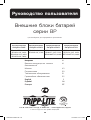
Bancos de batería
externas Serie BP
No conveniente para los usos móviles.
Módulos de Baterías
de 24V
Módulos de Bat-
erías de 36V
Módulos de Baterías
de 48V
Módulos de Baterías
de 72V
BP24V15RT2U, 14AH
BP24V28-2U, 28AH
BP24V36-2US, 36AH
BP24V70-3U, 70AH
BP36V15-2U, 18AH
BP36V42-3U, 21AH
BP48V24-2U, 18AH
BP48V27-2US, 27AH
BP48V60RT-3U, 42AH
BP72V15-2U, 15AH
BP72V18-2US, 18AH
BP72V28RT-3U, 28AH
18-09-336 93-36FF.indb 14 12/18/2018 8:27:06 AM

15
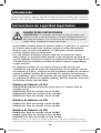
Introducción
Instrucciones de seguridad importantes
Los bancos de baterías externas Serie BP de Tripp Lite están diseñados para usarse con
diferentes UPS de Tripp Lite equipados con conectores para bancos externos de baterías.
GUARDE ESTAS INSTRUCCIONES
¡ADVERTENCIA! Los anaqueles de montaje no están diseñados para
soportar más de un banco de baterías. No apile múltiples bancos en un
sólo juego de anaqueles. El incumplimiento de esta advertencia puede
originar daños al producto o lesiones personales.
•
Sea precavido al levantar bancos de baterías. Debido a su gran peso, se requieren
por lo menos dos personas para ayudarlo a levantar e instalar dichos bancos.
• Asegúrese que sus bancos de baterías y su UPS usen el mismo voltaje de
corriente continua antes de conectarlos.
• Use solo módulos de baterías externas Tripp Lite con protección contra
sobrecorriente. La instalación debe llevarla a cabo únicamente personal de
servicio calificado. Póngase en contacto con Soporte al Cliente de Tripp Lite al
773.869.1234 para consultar el módulo de baterías externas apropiado que
se debe conectar.
• Los gabinetes metálicos de sus baterías externas están provistos por
seguridad de un medio de protección equipotencial. Al usar baterías externas
con conector de 2 pines, asegúrese de unir el gabinete metálico de su batería
externa al gabinete metálico del sistema UPS. Los módulos de baterías con
tres conductores / pines están equipados con una clavija de conexión a tierra.
Los gabinetes de plástico no requieren bonding. Para los requisitos de la cinta
de conexión a tierra, consulte abajo:
Módulos de Baterías de 24V
BP24V15RT2U: Gabinete de plástico, por lo que no se requiere Cinta de
conexión a tierra.
BP24V28-2U: Cinta de conexión a tierra 12 AWG
BP24V36-2US: Cinta de conexión a tierra 12 AWG
BP24V70-3U: Cinta de conexión a tierra 12 AWG
Módulos de Baterías de 36V
BP36V15-2U: Cinta de conexión a tierra 12 AWG
BP36V42-3U: Cinta de conexión a tierra 12 AWG
Módulos de Baterías de 48V
BP48V24-2U: Cinta de conexión a tierra 12 AWG
BP48V27-2US: Cinta de conexión a tierra 12 AWG
BP48V60RT-3U: Cinta de conexión a tierra 12 AWG
Nota: El conector de la batería en módulos de baterías de 72V tiene incorporada un clavija
para conexión a tierra, de modo que no se requiere una cinta adicional para conexión a tierra.
18-09-336 93-36FF.indb 15 12/18/2018 8:27:06 AM

16
Instrucciones de seguridad importantes
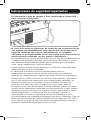
Fija firmemente la Cinta de conexión a tierra suministrada al sistema UPS
como se ilustra a continuación:
• El uso de este equipo en aplicaciones de soporte de vida en donde la falla de
este equipo pueda razonablemente hacer suponer que causará fallas en el
equipo de soporte de vida o afecte significativamente su seguridad o
efectividad, no está recomendado. No use este equipo en la presencia de una
mezcla anestésica inflamable con aire, oxigeno u óxido nitroso.
• Los procedimientos de montaje recomendados son para tipos de bastidores comunes
y pueden no ser apropiados para todas las configuraciones de bastidor. El usuario
debe determinar la idoneidad del bastidor, de los accesorios para el montaje en
pared y de los procedimientos, antes del montaje.
• Cuando se conectan varios bancos de baterías a un sólo UPS, estos deben tener
aproximadamente la misma antigüedad.
• Es normal que se produzcan chispas al conectar baterías externas.
• No desconecte las baterías externas del UPS mientras éste se encuentra en
operación con energía de batería, debido a que puede formarse un arco peligroso.
• Debido a que las baterías presentan un peligro de choque eléctrico y quemaduras
por las altas corrientes de cortocircuito, tome las precauciones adecuadas. No
deseche las baterías en un incinerador. No abra las baterías. No ponga los
terminales de la batería en corto o en puente con ningún objeto. Apague y
desconecte el UPS antes de reemplazar la batería. Sólo debe cambiar las baterías
personal técnico debidamente capacitado. Use herramientas con mangos aislados y
reemplace las baterías existentes con el mismo número y tipo de baterías nuevas
(plomo-ácido selladas). Las baterías del UPS son reciclables. Consulte la
reglamentación local para los requisitos de disposición de desechos o visita
http://www.tripplite.com/support/recycling-program para reciclar información. Tripp Lite
ofrece una línea completa de Cartuchos de reemplazo de batería para UPS (R.B.C.).
Visite Tripp Lite en la web en http://www.tripplite.com/products/battery-finder/ para
localizar la batería de reemplazo específica para su UPS.
18-09-336 93-36FF.indb 16 12/18/2018 8:27:06 AM

17
Montaje (Bastidor)
Monte su banco de baterías en un bastidor de 2 o 4 postes (vea la página 15] para
instalación de 2 postes). El usuario debe determinar la idoneidad de los materiales y
accesorios, así como de los procedimientos antes del montaje. Si los materiales y
procedimientos no son adecuados para su aplicación, contacte con el fabricante de su
bastidor. Los procedimientos descritos en este manual son para bastidores comunes y
de tipo caja y podrían no ser apropiados para todas las aplicaciones.
Montaje de 4 postes
La mayoría de los módulos de baterías externas incluyen el hardware requerido para su
instalación en 4 postes. Si este hardware no venía con su unidad, un Juego Ajustable
para Instalación en Rack de 4 postes (Modelo 4POSTRAILKIT) puede ser solicitado, por
separado.
1
Los ganchos plásticos
A
incluidos mantendrán temporalmente los estantes
rackmount vacíos
B
mientras usted coloca los accesorios de instalación
permanentes. Inserte un gancho cerca del centro del soporte frontal y posterior de
cada estantes como se muestra. (Cada soporte frontal tiene 6 orificios y cada
soporte posterior posee 3 orificios.) Los ganchos encajarán en su lugar.
Después de colocar los ganchos, expanda cada estante para que se ajuste con la
profundidad de los rieles de su rack. Los ganchos encajarán en los orificios
cuadrados en los rieles del rack para sostener los estantes. Consulte las etiquetas
de la unidad del rack para confirmar que los estantes estén nivelados en todas las
direcciones.
Nota: El reborde de soporte de cada estante debe quedar mirando hacia adentro.
B
B
1
A
A
A
A
18-09-336 93-36FF.indb 17 12/18/2018 8:27:06 AM

18
Montaje (Bastidor)
2U
3U
2
Asegure de manera permanente los estantes
B
a los rieles de montaje usando los
tornillos incluidos y las arandelas acopadas
C
como se muestra.
• Para montaje de equipos de 2U, coloque 4 tornillos en total en la parte frontal y
4 tornillos en total en la parte posterior.
• Para montaje de equipos de 3U, coloque 6 tornillos en total en la parte frontal y
4 tornillos en total en la parte posterior.
Apriete todos los tornillos antes de continuar.
Advertencia: No intente instalar su equipo hasta que haya insertado y
apretado los tornillos necesarios. Los ganchos plásticos no soportarán el
peso de su equipo.
2
2
C
C
C
C
B
B
18-09-336 93-36FF.indb 18 12/18/2018 8:27:07 AM

19
Montaje (Bastidor)
3U2U
3
Coloque los soportes de montaje de su equipo en los orificios de montaje
delanteros del gabinete usando los accesorios que vienen incluidos con su equipo.
Las “orejas” del soporte de montaje deben quedar mirando hacia adelante. (Puede
que algunos equipos tengan soportes de montajes preinstalados o integrados.)
3
4
Con la ayuda de un asistente (en caso de ser necesario), levante su equipo y
deslícelo en los estantes. Coloque los soportes de montaje del equipo en los rieles
de montaje delanteros con los tornillos y arandelas
D
suministradas por el
usuario. Apriete todos los tornillos de manera segura.
3U
2U
4
4
D
D
D
D
18-09-336 93-36FF.indb 19 12/18/2018 8:27:08 AM

20
Montaje de 2 postes (Telecomunicaciones)
Para instalar módulos de baterías para rack, en racks de 2 postes, se requiere un Juego
para Instalación en Rack de 2 postes de Tripp Lite (Modelo 2POSTRMKITWM o
2POSTRMKITHD). Si este Juego no venía con su unidad, puede ser solicitado, por
separado. Refiérase a la ilustración de abajo para instrucciones especificas de
instalación que abarca a los módulos de baterías 2U, 3U y 4U.
Importante: Las ilustraciones muestran las configuraciones de instalación más
típicas; su modelo puede variar. Use solamente los agujeros, para los tornillos,
preperforados para fijar las abrazaderas a los lados del módulo de baterías.
Cuando instale el módulo de baterías en el rack, asegúrese que el peso de la
unidad esté uniformemente distribuido.
2U
1
X 8
2U
2
X 4
3
X 2 X 2 X 2
3U
3U
4U
4U
X 8
X 4
X 4
X 4
Montaje (Bastidor)
X 8
X 4
1
1
2
2
3
3
18-09-336 93-36FF.indb 20 12/18/2018 8:27:10 AM
La page est en cours de chargement...
La page est en cours de chargement...
La page est en cours de chargement...
La page est en cours de chargement...
La page est en cours de chargement...
La page est en cours de chargement...
La page est en cours de chargement...
La page est en cours de chargement...
La page est en cours de chargement...
La page est en cours de chargement...
La page est en cours de chargement...
La page est en cours de chargement...
La page est en cours de chargement...
La page est en cours de chargement...
La page est en cours de chargement...
La page est en cours de chargement...
La page est en cours de chargement...
La page est en cours de chargement...
La page est en cours de chargement...
La page est en cours de chargement...
La page est en cours de chargement...
La page est en cours de chargement...
La page est en cours de chargement...
La page est en cours de chargement...
La page est en cours de chargement...
La page est en cours de chargement...
La page est en cours de chargement...
La page est en cours de chargement...
La page est en cours de chargement...
La page est en cours de chargement...
La page est en cours de chargement...
La page est en cours de chargement...
-
 1
1
-
 2
2
-
 3
3
-
 4
4
-
 5
5
-
 6
6
-
 7
7
-
 8
8
-
 9
9
-
 10
10
-
 11
11
-
 12
12
-
 13
13
-
 14
14
-
 15
15
-
 16
16
-
 17
17
-
 18
18
-
 19
19
-
 20
20
-
 21
21
-
 22
22
-
 23
23
-
 24
24
-
 25
25
-
 26
26
-
 27
27
-
 28
28
-
 29
29
-
 30
30
-
 31
31
-
 32
32
-
 33
33
-
 34
34
-
 35
35
-
 36
36
-
 37
37
-
 38
38
-
 39
39
-
 40
40
-
 41
41
-
 42
42
-
 43
43
-
 44
44
-
 45
45
-
 46
46
-
 47
47
-
 48
48
-
 49
49
-
 50
50
-
 51
51
-
 52
52


Tripp Lite BP Series External Battery Packs Le manuel du propriétaire
- Taper
- Le manuel du propriétaire
dans d''autres langues
Documents connexes
-
Tripp Lite BP Series External Battery Packs Le manuel du propriétaire
-
-
Tripp Lite BP24V70-3U Le manuel du propriétaire
-
-
-
-
-
-
Tripp Lite 4POSTRAILKITHD Le manuel du propriétaire
-