
M29857
68-0171EF-01
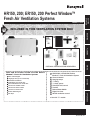
HR150, 200; ER150, 200 Perfect Window™
Fresh Air Ventilation Systems
PRODUCT DATA
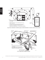
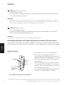
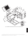
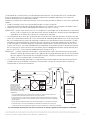
Included In thIs VentIlatIon system Box
Tools and accessories needed to install Perfect
Window™ Fresh Air Ventilation Systems
Wire cutter/stripper
18-gauge wire (up to 5 conductor)
Standard screwdriver
Insulated 6-inch round duct
Non-insulated 6-inch round duct
Two 6-inch weather hoods
Two 6-inch starter collars
1/2-inch I.D. drain hose
Airflow balancing kit
Foil tape
HR150/200 or ER150/200 Perfect
Window™ Fresh Air Ventilation System
Owner’s Manual
Hanging straps
* T-fitting
e
* 2 drain spouts
F1
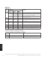
VisionPRO IAQ control
F2
TrueIAQ
F3
Dehumidistat H8908
F4
Digital fan timer
F5
W8150 ventilation control
*
Not with “C” models.
OPTIONAL CONTROLS SOLD SEPARATELY
*
*
e
F1 F3
F4 F5
GETTING
STARTED
MOUNTING PLUMBING WIRING APPENDICESDUCTING
F2


Perfect Window Fresh Air Ventilation Systems
NEED HELP? For assistance with this product please visit http://yourhome.honeywell.com
or call Honeywell Customer Care toll-free at 1-800-468-1502.
Read and save these instructions.
® U.S. Registered Trademark. Patents pending. Copyright © 2010 Honeywell International Inc. All rights reserved.
?
HR150, 200; ER150, 200 Perfect Window™ Fresh Air Ventilation Systems 68-0171EF—01
GETTING
STARTED
MOUNTING PLUMBING WIRING APPENDICESDUCTING
1
GETTING STARTED
Safety Definitions and Precautions . . . . . . . . . . . . . . 2
Application ................................. 3
Features .................................. 3
Planning the Installation . . . . . . . . . . . . . . . . . . . . . . 4
Sizing .................................. 5
Mounting Position and Location. . . . . . . . . . . . . . . . . 6
Balancing Airflow ............................ 9
MOUNTING
Installation ................................ 10
Suspended from Floor Joists .................. 10
PLUMBING
Installing Drain Line and P-Trap . . . . . . . . . . . . . . . 11
WIRING
Heat Recovery Ventilator (HRV) and
Energy Recovery Ventilator (ERV) Connections . . . 12
Digital Fan Timer . . . . . . . . . . . . . . . . . . . . . . . . . . . 12
DUCTING
Airflow Balancing ........................... 16
Balancing Procedure ........................ 16
APPENDICES
Startup and Checkout . . . . . . . . . . . . . . . . . . . . . . . 17
Cleaning Filters and Core .................. 17
Inspecting Exterior Hoods . . . . . . . . . . . . . . . . . 17
Troublshooting ............................. 18
Parts List ................................. 20
Specifications . . . . . . . . . . . . . . . . . . . . . . . . . . . . . 22

GETTING
STARTED
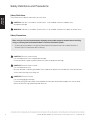
Safety Definitions and Precautions
Safety Definitions
These safety terms identify information you must read.
CAUTION: Indicates a hazardous situation which, if not avoided, could cause bodily injury
or property damage.
WARNING: Indicates a hazardous situation which, if not avoided, could result in death or serious injury.
Safety Precautions
CAUTION: Electrical shock hazard.
Can cause personal injury or equipment damage.
Disconnect power supply to prevent electrical shock or equipment damage.
CAUTION: Electrical Shock Hazard.
Can cause personal injury.
Be sure ventilator is correctly grounded. Confirm polarity of power line switched with safety (disconnect)
switch when cleaning or servicing unit.
CAUTION: Electrical Hazard.
Can cause equipment damage
Disconnect HRV/ERV from power source before connecting or disconnecting digital fan timer or other
device to HRV/ERV high-speed override terminals.
Make sure you read and understand the following safety and/or property hazards before installing,
using, or working with the Perfect Window™ Fresh Air Ventilation System:
All ducting to the outdoors must be terminated above anticipated snow lines and be fitted with a •
weather cap that incorporates bird screening.
HR150, 200; ER150, 200 Perfect Window™ Fresh Air Ventilation Systems 68-0171EF—01
2

GETTING
STARTED
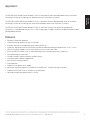
The HR150B and HR200B Perfect Window™ Fresh Air Ventilation Systems provide proper levels of ventilation
with energy savings by transferring heat between the exhaust and fresh air streams.
The ER150B and ER200B Perfect Window™ Fresh Air Ventilation Systems provide proper levels of ventilation
with energy savings by transferring heat and moisture between the exhaust and fresh air streams.
The ER150C and ER200C Perfect Window™ Fresh Air Ventilation Systems are specifically designed for
installations in unconditioned spaces such as attics and garages in regions where the outdoor temperature does
not drop below freezing.
Features
Remotely control two-speed fan.•
Integral balancing dampers for quick installation.•
Provides ventilation that helps contractors meet ASHRAE 62.•
Automatic, economical built-in frost control available for operation to design temperatures of -40°F (-40°C).•
HR150 and HR200 models have an easy-to-clean aluminum cross-flow core.•
ER150 and ER200 models have an advanced energy heat and moisture recovery fixed core.•
Washable energy transfer core.•
Includes vibration isolation hardware and duct collars.•
Insulated cabinet made of rugged steel.•
Permanent (washable) prefilters.•
Quiet operation.•
Digital fan timer option on all models.•
Advanced ventilation algorithms available on VisionPRO IAQ, TrueIAQ and W8150 controls.•
Interlock the ERV/HRV to an air handler or furnace blower.•
Dehumidistat operation deactivated in summer.•
Application
HR150, 200; ER150, 200 Perfect Window™ Fresh Air Ventilation Systems 68-0171EF—01
3

GETTING
STARTED
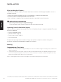
The Fresh Air Ventilation System is designed to
supply fresh air and exhaust stale air. The system
draws fresh outdoor air through the ventilator for
distribution throughout the house.
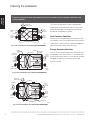
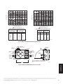
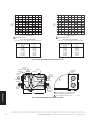
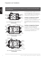
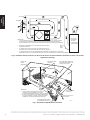
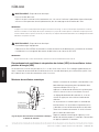
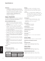
Heat Recovery Ventilator
Stale air is exhausted through the ventilator and to
the outdoors. Heat is transferred from one airstream
to the other as the air passes through the opposite
sides of the heat transfer core. See Fig. 1.
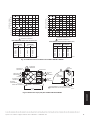
Energy Recovery Ventilator
Stale air is exhausted through the ventilator and to
the outdoors. Heat and moisture is transferred from
one airstream to the other as the air passes through
the opposite sides of the energy transfer core.
See Fig. 2 and 3.
Planning the Installation
Failure to comply with these requirements will result in voided warranty, improper installation, and
service callbacks.
STALE
AIR FROM
INSIDE
DEFROST
PORT
FRESH
AIR TO
INSIDE
FRESH AIR
FROM OUTSIDE
STALE
AIR TO
OUTSIDE
M29739
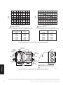
BALANCING DAMPER
FILTERS
Duct connections and airflow (ER150B/ER200B).Fig. 3.
FILTERS (2)
DRAIN
M29853
MOTOR
BLOWERS
FRESH AIR
FROM OUTSIDE
DEFROST
PORT
DRAIN PANS
BALANCING
DAMPER
BALANCING
DAMPER
CORE
STALE
AIR FROM
INSIDE
FRESH
AIR TO
INSIDE
STALE
AIR TO
OUTSIDE
FRESH
AIR TO
INSIDE
FRESH AIR
FROM OUTSIDE
M29861
MOTOR
MOTOR
STALE AIR
FROM HOUSE
ENERGY
TRANSFER
CORE
BALANCING
DAMPER
CORE
STALE AIR
TO OUTSIDE
BALANCING
DAMPER
FILTERS (2)
HR150, 200; ER150, 200 Perfect Window™ Fresh Air Ventilation Systems 68-0171EF—01
4
Duct connections and airflow (HR150B/HR200B).Fig. 1.
Duct connections and airflow (ER150C/ER200C).Fig. 2.

GETTING
STARTED
Sizing
ASHRAE 62.2
There are several methods that can provide
satisfactory results for sizing a ventilator to provide
adequate ventilation for a home. There is a new
residential ventilation standard, ASHRAE 62.2, that
suggests the following:
7.5 CFM per person (count people as 1 per •
bedroom plus 1) plus 1 CFM per 100 sq. ft.
Example:
2200 sq. ft. house with 4 bedrooms
= (7.5 CFM x (4 bedrooms + 1)) + (1 CFM x (2200 sq. ft. / 100))
= (7.5 x 5) + (2200 / 100)
= 37.5 + 22
= 59.5 CFM
In this case 60 CFM continuous would provide
satisfactory ventilation for this home.
ASHRAE 62.1
Some regions still use the previous standard, ASHRAE
62.1, as the code for ventilation in their region.
The ASHRAE Standard 62.1 Ventilation for Acceptable
Indoor Air Quality suggests the following:
.35 air changes per hour (ach) but not less than 15 •
cfm per person for living areas = house size (sq ft)
x ceiling height (ft) / 60 (min) x.35 (ach)
Example:
= 2000 sq ft x 8 ft / 60 min x .35 ach = 93 cfm
50 cfm intermittent or 20 cfm continuous capacity •
for bathrooms
Example:
50 cfm intermittent x 3 bathrooms = 150 cfm
20 cfm continuous x 3 bathrooms = 60 cfm
100 cfm intermittent or 25 cfm continuous capacity •
for kitchens
Example:
100 cfm intermittent x 1 kitchen = 100 cfm
25 cfm continuous x 1 kitchen = 25 cfm
Option 1: Fresh Air Ventilation System provides
continuous fresh air supply of 93 cfm, and intermittent
capacity for bathrooms of 150 cfm. A separate 100
cfm exhaust fan is used for the range hood.
Supply air flow required = 93 cfm
Exhaust air flow required = 150 cfm
Any Honeywell ventilation unit provides suitable
ventilation capacity. See Fig. 22.
Option 2: Fresh Air Ventilation System provides
continuous 93 cfm fresh air supply, 150 cfm
intermittent exhaust capacity for bathrooms and
continuous 50 cfm kitchen ventilation.
Supply air flow required = 93 cfm
Exhaust air flow required = 200 cfm
Honeywell HR200/ER200 have the exhaust capacity
required to meet the ventilation needs of this
application. See Fig. 22.
HR150, 200; ER150, 200 Perfect Window™ Fresh Air Ventilation Systems 68-0171EF—01
5

GETTING
STARTED
Mounting Position and Location
The HR150/ER150 and HR200/ER200 can be
suspended from exposed ceiling joists, ceiling surface
or floor mounted. (Level ventilator so drains function
correctly.)
NOTE: ER150C and ER200C are specifically designed
for installations in unconditioned spaces such as
attics and garages in regions where the outdoor
temperature does not drop below freezing. (These
units are not equipped with drain kits.)
Locate fresh air intake 6 ft (2m) or more from stale •
air exhaust to prevent exhaust air from re-entering.
Locate ventilator where length of ducting required •
is minimal.
Install HR150/ER150 and HR200/ER200 in a
conditioned space using these guidelines:
Pipe drain line (ER150C and ER200C do not have •
drain kits) from the ventilator to a drain.
Use an existing electrical outlet with appropriate •
current rating (or install one) close to ventilator
power cord.
Allow space for drain line by placing the ventilator •
at least 10 in. (254 mm) off the floor.
For access and removal of ventilator core, allow at •
least 25 in. (635 mm) of open space in front of unit.
INSULATED
FLEX DUCT
COLLAR ON
VENTILATOR
SEAL INTERIOR LINING OF
FLEX DUCT TO INSIDE COLLAR
SEAL OUTER LINING OF FLEX
DUCT TO OUTER COLLAR
M6557
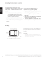
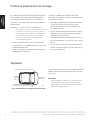
Ducting
Ducting between the ventilator and the outdoors must
be insulated and have a continuous air vapor barrier.
See Fig. 4.
IMPORTANT
All ducting to the outdoors must be terminated above
anticipated snow lines and be fitted with a weather cap
that incorporates bird screening.
HR150, 200; ER150, 200 Perfect Window™ Fresh Air Ventilation Systems 68-0171EF—01
6
Sealing insulated duct terminations.Fig. 4.

GETTING
STARTED
Design and installation of ductwork must be according to standard HVAC practice to deliver required quantities
of fresh air to temperature-controlled space and exhaust equivalent quantities of room air to the outside.
Keep intake and exhaust duct runs as short as possible with few bends or elbows.
Keep duct sizes as large as possible throughout the installation.•
Use a 6 in. diameter round duct for all connections to and from the ventilator.•
Separate outside intake and exhaust vents by at least 6 ft (2m).•
NOTES: Do not locate the fresh air vent where it blows directly onto occupants or the thermostat.
Do not locate the fresh air intake close to known sources of pollutants such as automobile exhaust, a
dryer vent or chimney smoke.
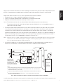
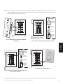
Ducting the supply outlet and/or the exhaust inlet of the ventilator to the return air plenum of the air handler •
is an excellent way to distribute fresh air and exhaust stale air from all parts of the house, while reducing
installation costs. When choosing this method, balance the ventilator when the air handler is running and
interlock the ventilator so that it can run only when the air handler runs. See Fig. 6. An alternate method is to
balance the ventilator when the air handler is not running and let the ventilator run whether the air handler is
running or not, see Fig. 5. An independent installation is shown in Fig. 7.
NOTE: When the home is occupied, continuous operation of the ventilator is recommended. When the furnace air handler
operates, fresh air is distributed through the heating/air conditioning supply registers. When the air handler is off,
fresh air is delivered through both supplies and returns.
An electrical interlock or an automatically powered damper must be used to prevent unwanted entry of •
outside air if the ventilator is turned off while the furnace air handler continues to operate.
COLD AIR
RETURN
EXHAUST AIR FROM
VARIOUS PARTS OF
HOME (BATHROOMS
IF REQUIRED; KITCHENS
IF REQUIRED; ROOMS
WITHOUT OPERABLE WINDOWS,
A
ND POTENTIALLY BASEMENTS).
FORCED AIR
FURNACE
COMBUSTION
OR ELECTRIC
M6549D
RETURN
AIR
OUTDOORS
NOTES:
1.
2.
3.
4.
FURNACE BLOWER NEED NOT OPERATE TO PROVIDE GOOD AIR DISTRIBUTION/QUALITY WITH THIS SYSTEM.
IF FURNACE BLOWER OPERATION IS REQUIRED TO HELP DISTRIBUTE SUPPLY AIR: RUN CONTINUOUSLY
OR INTERLINK ELECTRICALLY (LOW VOLTAGE).
NO SEPARATION REQUIREMENTS ARE NECESSARY BETWEEN DIRECT CONNECTION POINT AND FURNACE.
WEATHER-HOOD ARRANGEMENT IS FOR DRAWING ONLY. 6 FT (2m) MINIMUM SEPARATION REQUIRED,
18 IN. (0.46m) ABOVE GRADE MINIMUM.
HR150, 200; ER150, 200 Perfect Window™ Fresh Air Ventilation Systems 68-0171EF—01
7
Direct connection of supply air stream to furnace cold air return for HRV/ERV.Fig. 5.

GETTING
STARTED
40 IN. (1m) MINIMUM
COLD AIR
RETURN
FORCED AIR
FURNACE
COMBUSTION
OR ELECTRIC
M6548E
RETURN
AIR
OUTDOORS
NOTES:
1.
2.
3.
4.
FURNACE BLOWER IS REQUIRED TO OPERATE WHEN VENTILATION IS REQUIRED.
SET THE FURNACE BLOWER TO RUN CONTINUOUSLY, OR INTERLINK ELECTRICALLY
(LOW VOLTAGE).
MINIMUM SEPARATION OF 40 IN. IS REQUIRED BETWEEN THE TWO
DIRECT CONNECTIONS.
EXHAUST AIR CONNECTION SHOULD BE UPSTREAM OF THE SUPPLY
AIR CONNECTION TO PREVENT EXHAUSTING ANY FRESH AIR.
WEATHER-HOOD ARRANGEMENT IS FOR DRAWING ONLY. 6 FT. (2 m)
MINIMUM SEPARATION REQUIRED, 18 IN. (0.46m) ABOVE GRADE MINIMUM.
ADJUSTABLE FRESH
AIR SUPPLY
ADJUSTABLE DAMPERS FOR
BALANCING AIR FLOW INTO
AND OUT OF THE HOUSE
FRESH AIR
SUPPLY HOOD
STALE AIR
EXHAUST HOOD
FLEXIBLE INSULATED DUCTING
WITH A VAPOR BARRIER
VENTILATOR EXHAUSTS FROM KITCHEN AND/OR
BATHROOMS OR OTHER CENTRAL LOCATIONS
TO OUTDOORS.
VENTILATOR SUPPLIES OUTDOOR AIR DIRECTLY TO
EACH BEDROOM, TO EACH FLOOR WITHOUT A
BEDROOM, AND TO THE PRINCIPAL LIVING AREAS.
ADJUSTABLE
STALE AIR
RETURN
M4911A
NOTES:
1.
2.
HR150, 200; ER150, 200 Perfect Window™ Fresh Air Ventilation Systems 68-0171EF—01
8
Direct connection of ventilator supply air stream and exhaust air stream to furnace cold air return.Fig. 6.
Independent ventilator installation.Fig. 7.

GETTING
STARTED
Balancing Airflow
Balancing the airflow verifies that the Fresh Air
Ventilation System is delivering the intended airflow
and energy performance. Use the Airflow Balancing
instructions in the Installation section to check and
balance the airflow.
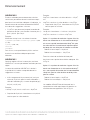
Controls
Remote Override Switch Functions On/Off Control
If continuous ventilation is not required, an on/off
control can be used to activate the ventilator when it is
switched to Standby. Controls that can be used for this
function include dehumidistats, timers, wall switches
and the ventilate function of the VisionPRO IAQ and
TrueIAQ digital controls.
Dehumidistat
If moisture control in bathrooms is a primary function
of the system, a dehumidistat can be used to switch
the ventilator from a Low or Standby setting to the High
setting. Moisture removal throughout the entire home
can only be achieved when the outside air contains
less moisture than the inside air (typically during cold
weather conditions).
An HRV will override a call from the dehumidistat if
the outdoor temperatures exceed 60°F (15.6°C) for
a 24-hour period. The dehumidistat function will be
re-enabled if the unit is unplugged for 3 minutes or if
the outdoor temperature drops below 60°F (15.6°C)
for a 24-hour period. The dehumidistat function is
permanently enabled in ERVs.
IAQ Controls
The VisionPRO IAQ and TrueIAQ controls can
automatically control the ventilator by pressing the
Ventilate button on the control. See the control owner’s
guide for complete instructions.
Digital Fan Timer
The ventilator controls are compatible with the Digital
Fan Timer. If more than one timer is activated, each
runs independently with the ventilator running at high
speed until all timers have timed out. Up to eight timers
can be installed in a system.
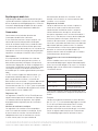
Moisture Control
When a building is new, there is excess moisture in
the wood, plaster, cement and other construction
materials. When the new building is occupied, the
activities of the occupants also increase the moisture
level. There can also be high levels of formaldehyde
and other chemicals that were used in the building
materials. Running the ventilation system on high
speed provides optimum indoor air pollutant reduction.
High speed also provides maximum moisture removal
when the outside air contains less moisture than the
inside air. (Typically during cold weather conditions.)
Operating Damper Frost Control
Some models have an electronically-controlled damper
frost control mechanism to prevent frost buildup on the
core. Defrost timing will change based on incoming
outdoor air temperature.
Outdoor Temperauture Defrost Timer*
27 °F (-3 °C) 3 minute defrost/25 minute run
-4 °F (-20 °C) 4.5 minute defrost/17 minute run
-31 °F (-35 °C) 7 minute defrost/15 minute run
* The R2000 jumper on the control board can be
removed to meet R2000 program requirements.
Example:
When the outside temperature drops below 27 °F
(-3 °C), the defrost timer is activated. At the end of the
25 minute run cycle, when the core can experience
some nominal frost buildup, the timer activates a
motor-driven damper door that simultaneously opens
the defrost port and closes off the supply air port.
HR150, 200; ER150, 200 Perfect Window™ Fresh Air Ventilation Systems 68-0171EF—01
9

MOUNTING
When Installing this Product…
1. Read these instructions carefully. Failure to follow these instructions could damage the product or cause a
hazardous condition.
2. Check the ratings on the product to make sure the product is suitable for your application.
3. Installer must be a trained, experienced service technician.
4. After installation is complete, check out product operation as provided in these instructions.
CAUTION: Electrical Shock Hazard.
Can cause personal injury or equipment damage.
Disconnect power supply to prevent electrical shock or equipment damage.
Unpacking Fresh Air Ventilation System
Check that all the components are included. The Fresh Air Ventilation System is shipped assembled. The carton
contains the following:
Fresh Air Ventilation System.•
Vibration isolation straps (4).•
Drain fittings (2) and T fitting (1).•
Literature package.•
Except for the mounting hardware and drain fittings, the ventilator is ready for installation. Wiring, drain
connections and ducting are required to complete the installation.
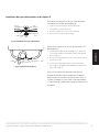
Mounting
Suspended from Floor Joists
Mount the four vibration isolation straps (provided) to the side of the ventilator using the mounting screws located on the 1.
cabinet. See Fig. 23.
Securely fasten the other ends of the straps to the floor joists with wide-head nails (not supplied), making sure the unit 2.
is level. The straps are designed to reduce noise, resonance or harmonics; therefore, using the full length of the strap
between the ventilator and the floor joists is recommended.
NOTE: Removing door and core reduces the weight of the ventilator, making it easier to lift into place.
INSTALLATION
HR150, 200; ER150, 200 Perfect Window™ Fresh Air Ventilation Systems 68-0171EF—01
10

PLUMBING
Installing Drain Line and P-Trap
M6552
DRAIN
PAN
O RING
HR
BOTTOM
WASHER
NUT
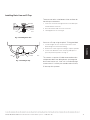
Installing drain line.Fig. 8.
There are two holes at the bottom of the ventilator for
the drain pan connectors.
Insert the connectors through the hole in the drain pan 1.
and the bottom of the unit.
Place the washer and nut on the connector.2.
Hand tighten the nut. See Fig. 8.3.
TO DRAIN
T FITTING
TAPE
M6551
Installing P-trap.Fig. 9.
Construct a P-trap using the plastic T-fitting provided.
Cut two lengths of 1/2 in. ID hose and connect each 1.
drain fitting to the end of the T-fitting.
Position the center leg of the T-fitting so it points upward.2.
Connect the drain line to the center leg and tape it in 3.
place to prevent any kinks. See Fig. 9.
This creates a trap that will hold some condensation
and prevent odors from being drawn up through the
drain hose into the unit. If the unit is installed during a
season when it is unlikely that condensation will form,
fill the trap with tap water.
HR150, 200; ER150, 200 Perfect Window™ Fresh Air Ventilation Systems 68-0171EF—01
11

WIRING
WIRING
CAUTION: Electrical shock hazard.
Can cause personal injury.
Be sure ventilator is correctly grounded. Confirm polarity of power line switched with safety (disconnect)
switch when cleaning or servicing unit.
IMPORTANT
The hot line (black) is the correct line to switch. See Fig. 19. To confirm correct polarity, use voltmeter or test lamp to
verify there is no power after the switch when the door is open. Check between that point and ground (on cabinet). This
process must be used because occasionally some dwellings are incorrectly wired.
CAUTION: Electrical hazard.
Can cause equipment damage.
Disconnect HRV/ERV from power source before connecting or disconnecting digital fan timer or other
device to HRV/ERV high-speed override terminals.
IMPORTANT
Do not connect external power sources to the highspeed override terminals.
Heat Recovery Ventilator (HRV) and Energy Recovery Ventilator (ERV) Connections
The connector is a three-prong, 120 Vac plug with ground. If further wiring is required, Honeywell recommends
that a licensed electrician make all electrical connections. It is very important that the unit be correctly grounded.
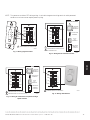
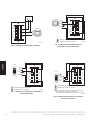
Digital Fan Timer
M29806
HIGH SPEED
STATUS LIGHTS
SELECT BUTTON
INITIATES HIGH
SPEED VENTILATION
FOR 20, 40 OR 60
MINUTES
YELLOW
RED
GREEN
Digital fan timer lights and Select Button.Fig. 10.
Mount digital fan timer in a full or one-half depth
electrical box in the living space. See Fig 10.
Press and release the Select Button to activate high
speed on the ventilator. Change between 20-, 40-, and
60-minute override times by pressing and releasing
the Select Button.
The status light will dim after 10 seconds of run time.
The status light will flash during the last 5 minutes of
override. All timers connected to the unit will illuminate
for the duration of the override.
Set the lockout mode by holding the Select Button for
5 seconds. Unlock by holding for 5 seconds.
HR150, 200; ER150, 200 Perfect Window™ Fresh Air Ventilation Systems 68-0171EF—01
12

WIRING
1
2
3
4
5
6
7
8
9
10
VNT
LOW
RED
YEL
GRN
VNT HI
G
F
R
G
T
DSTAT
M29844
JUMPER BETWEEN VNT COM AND RED.
CHOOSE AMONG AVAILABLE CONTROLS.
ALL WIRE IDENTICALLY.
1
1
2
2
VISIONPRO
IAQ VNT1, 2
TERMINALS
O
10
20
30
40
50
60
W8150
AUX
TERMINALS
CONTROL OPTIONS
MECHANICAL
TIMER DRY
CONTACTS
TRUE IAQ VENT
TERMINALS
68
40
55
1215
:
76
%
%
In
Out
PM
VNT
COM
1
2
3
4
5
6
7
8
9
10
VNT
LOW
RED
YEL
GRN
VNT HI
G
F
R
G
T
DSTAT
M29846
JUMPER BETWEEN VNT COM AND RED.
1
1
20 40 60 TIMER
FAN INTERLOCK
VNT
COM
1
2
3
4
5
6
7
8
9
10
VNT
LOW
VNT
COM
RED
YEL
GRN
VNT HI
G
F
R
G
T
DSTAT
M29845
JUMPER BETWEEN VNT COM AND RED.
JUMPER BETWEEN VNT COM AND VNT LOW.
1
1
VISIONPRO
IAQ VNT1, 2
TERMINALS
O
10
20
30
40
50
60
W8150
AUX
TERMINALS
MECHANICAL
TIMER DRY
CONTACTS
2
TRUE IAQ VENT
TERMINALS
2
68
40
55
1215
:
76
%
%
In
Out
PM
20 40 60 TIMER
FAN INTERLOCK
CONTROL OPTIONS
Wiring digital fan timer.Fig. 11.
Wiring IAQ or ventilation control.Fig. 12.
Wiring for continuous low speed and high Fig. 13.
speed override.
Wiring dehumidistat.Fig. 14.
1
2
3
4
5
6
7
8
9
10
VNT
LOW
VNT
COM
RED
YEL
GRN
VNT
HI
G
F
R
G
T
DSTAT
20 40 60 TIMER
FAN INTERLOCK
M29838
YEL
RED
GRN
JUMPER BETWEEN VNT COM AND RED.
1
1
NOTE: Turn power to ventilator OFF during wiring. A static discharge to the wiring terminals while powered
could cause unit to reset or require power cycling.
HR150, 200; ER150, 200 Perfect Window™ Fresh Air Ventilation Systems 68-0171EF—01
13

WIRING
1
2
3
4
5
6
7
8
9
10
VNT
LOW
VNT
COM
RED
YEL
GRN
VNT HI
G
F
R
G
T
DSTAT
M29848
JUMPER BETWEEN VNT COM AND RED.
JUMPER BETWEEN DHM2 AND VNT1.
1
1
2
2
DHM 1
DHM 2
VNT 1
VNT 2
VisionPRO IAQ
20 40 60 TIMER
FAN INTERLOCK
1
2
3
4
5
6
7
8
9
10
VNT
LOW
VNT
COM
RED
YEL
GRN
VNT HI
G
F
R
G
T
DSTAT
M29849
JUMPER BETWEEN VNT COM AND RED.
JUMPER BETWEEN VENT AND DEHUM.
1
1
2
2
VENT
VENT
DEHUM
DEHUM
68
40
55
1215
:
76
%
%
In
Out
PM
TrueIAQ
20 40 60 TIMER
FAN INTERLOCK
1
2
3
4
5
6
7
8
9
10
VNT
LOW
VNT
COM
RED
YEL
GRN
VNT HI
G
F
R
G
T
DSTAT
M29850
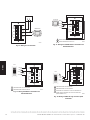
JUMPER BETWEEN VENT AND DEHUM.
JUMPER BETWEEN VNT COM AND RED.
LOW SPEED WILL OPERATE IF TrueIAQ IS CONFIGURED TO
LOWER VENTILATION BASED ON OUTDOOR CONDITIONS
(SETUP NUMBER 115=2).
1
2
2
68
40
55
1215
:
76
%
%
In
Out
PM
VENT
VENT
DEHUM
DEHUM
TrueIAQ
1
3
3
20 40 60 TIMER
FAN INTERLOCK
Wiring for fan interlock.Fig. 15.
Wiring VisionPRO IAQ for ventilation and Fig. 16.
dehumidification.
Wiring TrueIAQ for ventilation and Fig. 17.
dehumidification.
Wiring TrueIAQ for high and low speed Fig. 18.
ventilation.
1
2
3
4
5
6
7
8
9
10
VNT
LOW
VNT
COM
RED
YEL
GRN
VNT HI
G
F
R
G
T
DSTAT
M29847
THERMOSTAT
R
G
FURNACE
G
R
20 40 60 TIMER
FAN INTERLOCK
HR150, 200; ER150, 200 Perfect Window™ Fresh Air Ventilation Systems 68-0171EF—01
14

WIRING
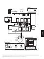
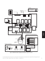
LEGEND
HIGH VOLTAGE
12V LOW VOLTAGE
M29742
K7K2 K3
P2
RED
THERMISTOR
(NOT ON ALL UNITS)
BLACK
GREEN
NEUTRAL
LINE
AUTO-
TRANSFORMER
SEE
DEFROST
DETAIL
WHITE
P4
BLUE
K4
K6 K1
P3
FAN O/P
T8T7
P1
T3T2
T9
T1
K5
DIRECT
MOUNTED
CAPACITOR
CAPACITOR
DEFROST DETAILS
PCB PLUG-IN
PLUG IN
CONNECTOR
BLACK
RED
ORANGE
ORANGE
12
P1
34
PIN 1–BLACK
PIN 2–ORANGE
PIN 3–RED
PIN 4–SPARE
RED
BLACK
BI-DIRECTIONAL
DAMPER MOTOR
PCB PLUG-IN
12
P1
34
PIN 1–RED
PIN 2–ORANGE
PIN 3–BLACK
PIN 4–SPARE
FAN
MOTOR
BROWN
BROWN
GREEN
BLACK
WHITE
VNT
LOW
VNT
COM
RED
YEL
GRN
VNT HI
G
F
R
G
T
DSTAT
AUTO-TRANSFORMER DETAIL
PIN 1–BLUE
PIN 2–YELLOW
PIN 3–BROWN
PIN 4–RED
PIN 5–WHITE
PIN 6–BLACK
PIN 1–GREEN
PIN 2–GREEN
P5
AUTO
TRANSFORMER
4
5
6
1
2
3
1
2
P6
P5
PLUG-IN CONNECTOR
P6
Internal schematic for fresh air ventilation systems.Fig. 19.
HR150, 200; ER150, 200 Perfect Window™ Fresh Air Ventilation Systems 68-0171EF—01
15

DUCTING
Airflow Balancing
Volume-balanced airflow in the ventilator is required. Volume of outside air brought in must equal the volume of
air the unit exhausts. If airflow is not correctly balanced:
unit does not operate at its maximum efficiency.•
negative or positive air pressure can occur in the house.•
unit will not defrost properly.•
warranty can be voided.•
Excessive positive pressure can drive moist indoor air into building external walls where it can condense (in cold
weather) and degrade structural components. Moist indoor air can also cause keyholes to freeze.
Excessive negative pressure can have several undesirable side effects; in some geographic locations, soil
gases such as methane and radon can be drawn into the home through basement/ground contact areas.
Excessive negative pressure can also cause back drafting of vented combustion equipment when adequate
combustion air supply is not provided.
Balancing Procedure
Six-inch (150 mm) diameter flow collars connected to inclined or digital manometer, or magnehelic, with
range of 0 to.25 in. (0 to 62.5 Pa) of water are recommended for accurate airflow measurements. To avoid
airflow turbulence and incorrect readings, flow stations should be located at a distant point of at least five duct
diameters; for example, 6 in. (150 mm) duct requires five diameters x 6 in. (150 mm) = 30 in. (76 cm) from
nearest valve or flow restriction. This requirement applies to both stale air to exchanger duct and fresh air to
house duct.
Before balancing, make sure:
all sealing of the ductwork system is completed.•
all of the ventilator system components are in place and functioning properly.•
balancing dampers are fully open.•
unit is on High speed.•
airflows in branch lines to specific areas of house are adjusted before balancing the unit. (A smoke pencil •
used at the grilles is a good indicator of relative airflow for each branch line.)
HVAC fan is on for models ducted into HVAC system.•
PUSH AND TURN WITH
SLOTTED SCREWDRIVER.
DAMPER AUTOMATICALLY
LOCKS WHEN PRESSURE
IS RELEASED.
M13462
Balancing airflow.Fig. 20.
After taking readings in stale air and fresh air ducts,
duct with lower cfm (L/s) velocity reading should
remain as is, while duct with higher reading should be
dampered back to match lower reading. See Fig. 20.
Return unit to appropriate fan speed for normal
operation.
HR150, 200; ER150, 200 Perfect Window™ Fresh Air Ventilation Systems 68-0171EF—01
16

APPENDICES
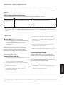
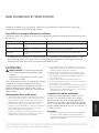
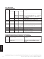
When the ventilator is powered up it will go through a self-test and turn on both fan speeds and check damper
operation.
LED on Terminal Board of Ventilator
The terminal board has an LED that flashes to indicate the current mode of the ventilator.
Ventilator Mode Flashing Sequence Description
Standby, Ventilating,
or Off*
½ sec. on followed by 10 sec. off This is the normal operation of the ventilator.
Self-Test 2-½ sec. on followed by ½ sec. off Self-test will turn on both fan speeds and check damper
operation.
Defrost ½ sec. on followed by ½ sec. off See page 9 for defrost operation
* In Off mode the ventilator will not come on. The ventilator is in Off mode when there is no jumper between
VNT COM and RED. The jumper can be replaced with an ON/OFF light switch to provide an easy positive off
switch.
STARTUP AND CHECKOUT
SERVICE
CAUTION: Electrical shock hazard.
Can cause personal injury or equipment damage.
Disconnect power to unit before starting
maintenance.
For maximum efficiency, the Fresh Air Ventilation
System must be maintained on a regular basis.
Honeywell recommends checking and cleaning at
least twice a year, preferably at the beginning of each
heating and cooling season.
Cleaning Filters and Core
Open ventilator door by loosening draw latches on top of 1.
unit and swinging door open. For easier access, remove
door by moving it right to disengage hinges.
Carefully grip ends of core, (be careful not to damage 2.
aluminum fins); then pull evenly outward. Core fits tightly,
but slides out of channels.
Once core is removed, filters can be removed by 3.
removing clips holding them in place. Note clip
installation for reassembly.
ERV core: Vacuum the ERV core or rinse with cold water. 4a.
Do not use soap, dishwasher, or a pressure washer.
HRV core: Soak and rinse the HRV core in warm soapy 4b.
water. Do not use cleaning solutions, dishwasher or a
pressure washer.
Wash the filters in warm soapy water.5.
Place the clean filter (wet or dry) over the core and 6.
secure it in place with the clips.
Reinstall core by sliding it into the four corner channels. 7.
(Water cannot damage gasket and label on core ends,
so it is not necessary to remove them from the core.)
Inspecting Exterior Hoods
Inspect exterior hoods at least monthly. Be sure
exhaust and fresh air supply hoods are not blocked
or restricted by leaves, grass or snow. In winter, be
sure snow does not block hoods and frost does not
accumulate on wire mesh bird screen.
IMPORTANT
Blocked hoods can cause house/building pressure
change that can lead to possible combustion product
spillage from heating appliances.
HR150, 200; ER150, 200 Perfect Window™ Fresh Air Ventilation Systems 68-0171EF—01
17

APPENDICES
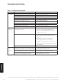
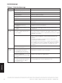
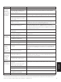
Table 1. Troubleshooting Guide.
Symptom Cause Solution
Poor airflow Plugged outside hood 1/4 in. (6 mm) mesh.• Clean exterior hoods or vents•
Filters plugged.• Remove and clean filter.•
Core obstructed.• Remove and clean core.•
House grilles closed or blocked.• Check and open grilles.•
Dampers (if installed) are closed.• Open and adjust dampers•
Poor power supply at site.• Have electrician check supply voltage at house.•
Ductwork is restricting airflow.• Check duct installation.•
Improper speed control setting.• Increase speed of ventilator.•
Ventilator airflow improperly balanced.• Have contractor balance ventilator airflow.•
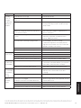
Supply air
feels cold
Poor location of supply grilles, airflow can •
irritate the occupant.
Locate grilles high on walls or under baseboard •
heaters; install ceiling-mounted diffuser or
grilles to avoid blowing directly on occupants
(example: over a sofa).
Outdoor temperature extremely cold.• Turn down ventilator supply speed.•
Use a small duct heater (1 kW) to temper the •
supply air.
Placement of furniture or closed doors is •
restricting movement of air in the home.
If supply air is ducted in furnace return, run •
furnace fan continuously to distribute ventilation
air comfortably.
Ventilator airflow can be incorrectly balanced.• Have a contractor balance ventilator airflow.•
Dehumidistat
is not
operating
Incorrect connection to external 24-volt control.•
Staple/nail is shorting out external low voltage.•
Check that correct wires were used.•
Check external wiring for a short.•
Check dehumidistat setting; it could be at Off.• Set dehumidistat at the desired setting.•
Dehumidistat is disabled when the outdoor •
temperature is above 60F for 24 hours.
Check the LED on the terminal block for long •
flash followed by a short flash.
TROUBLESHOOTING
HR150, 200; ER150, 200 Perfect Window™ Fresh Air Ventilation Systems 68-0171EF—01
18
La page est en cours de chargement...
La page est en cours de chargement...
La page est en cours de chargement...
La page est en cours de chargement...
La page est en cours de chargement...
La page est en cours de chargement...
La page est en cours de chargement...
La page est en cours de chargement...
La page est en cours de chargement...
La page est en cours de chargement...
La page est en cours de chargement...
La page est en cours de chargement...
La page est en cours de chargement...
La page est en cours de chargement...
La page est en cours de chargement...
La page est en cours de chargement...
La page est en cours de chargement...
La page est en cours de chargement...
La page est en cours de chargement...
La page est en cours de chargement...
La page est en cours de chargement...
La page est en cours de chargement...
La page est en cours de chargement...
La page est en cours de chargement...
La page est en cours de chargement...
La page est en cours de chargement...
La page est en cours de chargement...
La page est en cours de chargement...
La page est en cours de chargement...
La page est en cours de chargement...
La page est en cours de chargement...
La page est en cours de chargement...
La page est en cours de chargement...
La page est en cours de chargement...
La page est en cours de chargement...
La page est en cours de chargement...
-
 1
1
-
 2
2
-
 3
3
-
 4
4
-
 5
5
-
 6
6
-
 7
7
-
 8
8
-
 9
9
-
 10
10
-
 11
11
-
 12
12
-
 13
13
-
 14
14
-
 15
15
-
 16
16
-
 17
17
-
 18
18
-
 19
19
-
 20
20
-
 21
21
-
 22
22
-
 23
23
-
 24
24
-
 25
25
-
 26
26
-
 27
27
-
 28
28
-
 29
29
-
 30
30
-
 31
31
-
 32
32
-
 33
33
-
 34
34
-
 35
35
-
 36
36
-
 37
37
-
 38
38
-
 39
39
-
 40
40
-
 41
41
-
 42
42
-
 43
43
-
 44
44
-
 45
45
-
 46
46
-
 47
47
-
 48
48
-
 49
49
-
 50
50
-
 51
51
-
 52
52
-
 53
53
-
 54
54
-
 55
55
-
 56
56


Honeywell ER150B Guide d'installation
- Taper
- Guide d'installation
- Ce manuel convient également à
dans d''autres langues
- English: Honeywell ER150B Installation guide
Documents connexes
-
Honeywell VNT5150H1000 Manuel utilisateur
-
Honeywell TrueCLEAN Manuel utilisateur
-
-
-
-
-
-
Honeywell Dehumidifier H8908C/D Manuel utilisateur
-
Honeywell Dehumidifier DR90 Manuel utilisateur
-
Autres documents
-
Lifebreath RNC series Le manuel du propriétaire
-
Fantech 405335 Guide d'installation
-
NAPOLEON NHRV75S Manuel utilisateur
-
 Venmar K7 HRV Mode d'emploi
-
Fantech FIT 70E Guide d'installation
-
Air King DH55 Manuel utilisateur
-
-
-
Bryant ERVCRSVB Le manuel du propriétaire
-
