

ATTAX 100™ Manual
Foreword
Thank you for choosing a Hughes & Kettner® product.
With the ATTAX 100™, you now own a unique
guitar-driven sound system that offers everything
you need to have a blast at rehearsals and on stage.
We factored the wishes and suggestions of many
guitarists into the design of the ATTAX 100™, aiming
to turn up a modern guitar amp that would stand as a
benchmark DFX amp. We accomplished what we set
out to achieve. No comparable amp comes close to
matching the ATTAX 100™’s sound quality, flexibility,
performance and handling convenience.
Your ATTAX 100™’s nerve center is the inno-
vative Autostore FX MATRIX™. For the first time,
an amp in this class is able to store individual effect
settings separately for every channel. And it does
this automatically, without requiring additional
programming steps. Finally, an ingenious function has
arrived that makes the DFX amp a true gigging rig!
The ATTAX 100™ is equipped with a digital multi FX
processor offering popular effects such as REVERB,
DELAY, CHORUS, FLANGER and TREMOLO in
remarkably high quality. Four channels, a Current
Feedback power amp and 12" RockDriver Ultra
speakers deliver the goods – soul-stirring tone. When
you power up and plug in, you’ll hear 20 years of
Hughes & Kettner® amp engineering experience
reflected in that tone.
Whether you opted for the combo or the head, rest
assured that the ATTAX 100™ delivers the kind of
inspiring response that is sure to supercharge your
playing while practicing and performing on the big
stage. You wanted it all – powerful and G-force sound
pressure, crystal-clear clean sounds, creamy CRUNCH
and lead tones, fire-breathing ULTRA sounds, and
authentic effects. Now you got it, in a great, easily
handled gigging amp to boot.
Here’s wishing you tons of fun
with your new ATTAX 100™!
Table of Content
1 Overview of Control Features
and Connectors 9
1.1 Selecting Channels and Effect Parameters 9
1.2 Instrument Inputs, Channels and Master Volume 9
1.3 Mains Switch and Mains Socket 9
1.4 Speaker out 9
1.5 Headphones out 9
1.6 LINE OUT 10
1.7 CD/LINE INPUT 10
1.8 FX SEND/RETURN 10
1.9 FOOTSWITCH 10
1.10 FX ON/OFF 10
1.11 FX-ON/OFF Programming 10
2
The ATTAX 100’s four Channels 10
2.1 CLEAN 10
2.1.1 CLEAN VOL 10
2.1.2 CLEAN Voicing Section 10
2.2 CRUNCH 10
2.2.1 CRUNCH GAIN 11
2. 2.2 CRUNCH VOL 11
2.3 LEAD 11
2.3.1 LEAD/ULTRA-GAIN 11
2.3.2 LEAD VOL 11
2.4 ULTRA 11
2.4.1 ULTRA VOL 11
2.5 CRUNCH, LEAD, ULTRA Voicing Section 11
3
The ATTAX 100’s Effects 11
3.1 MOD FX 11
3.1.1 CHORUS 11
3.1.2 FLANGER 11
3.1.3 TREMOLO 11
3.2 DELAY 11
3.3 REVERB 11
4
Technical Specifications 12
8

ATTAX 100™ Manual
english
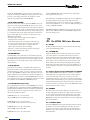
1 Overview of Control
Features and Connectors
1.1 Selecting channels and effect parameters
Use buttons 1 to 4 to select the ATTAX 100™’s four channels, CLEAN,
CRUNCH, LEAD and ULTRA. These buttons correspond to the buttons
on the included footswitch. When the footswitch is connected, buttons
1 to 4 serve display purposes only, and the footswitch switches
channels.
Use knobs 5 to 8 to adjust the effect for the given channel. The FX
MATRIX Autostore function automatically saves the edited effect
settings for every channel. You do not need to store settings separately.
Even if the amp is suddenly switched off or power fails, the FX MATRIX
will recall your settings.
1.2 Instrument inputs, channels and master volume
Connect your guitar to input 9. Please use high-quality shielded cords only.
Use knobs 10 to 21 to shape the sound and determine the volume of
individual channels. You’ll find a detailed description of the channels in
section 2. Knob 22 determines the amp’s overall volume level. Always
turn the MASTER knob all the way down – that is, counterclockwise as
far as it will go - before powering your amp up.
Knobs 10 to 22 work in the same tried-and-true manner as the controls
on a classic amp. These settings are not stored. This means that the
actual position of the knob determines the amp’s sounds.
1.3 Mains switch and mains socket
Use switch 23 to turn the ATTAX 100 on and off. Make a habit of
checking to make sure that the switch is set to the OFF position before
you connect the power cable to a mains power supply. The ATTAX 100
ships with a separate power cord that connects to socket 24. Please
ensure that the mains voltage matches the value indicated on the back
panel of the ATTAX 100™. Get in touch with your Hughes & Kettner®
dealer immediately if this is not the case or the included mains cord’s
plug does not fit into the wall outlet.
1.4 Speaker out
Use jack or jack pair 25, EXTERNAL SPEAKER or SPEAKERS, to connect
speakers. All speakers are connected in parallel for both the combo and
the head.
ATTAX 100™ COMBO
EXTERNAL SPEAKER: Connect cabinets with 8 ohms minimum
impedance to this jack. The impedance of connected speakers must
never be lower than 8 ohms!
ATTAX 100™ HEAD
SPEAKERS: You can connect two cabinets to the head. The minimum
impedance is 4 ohms; ensure your rig’s impedance never drops below
4 ohms! If you plug cabs into both jacks, each cabinet’s impedance
must be 8 ohms or higher. If you plug a cab into just one jack, its
impedance must be 4 ohms or higher.
1.5 Headphones out
Connect standard stereo headphones to jack 26, HEADPHONES.
Adjust the volume via the MASTER knob. Always plug in a stereo 1/4"
jack when connecting headphones. The headphones output may be
damaged if you insert a mono plug into the jack. The ATTAX 100™
speaker output is deactivated when a plug is inserted into this jack.
1.6 LINE OUT
Use jack 27, LINE OUT, (mono 1/4" jack) to patch out the amp’s signal,
including all effects, to another power amp or a DI box (for example,
the Hughes & Kettner® RED BOX®).
1.7 CD/LINE INPUT
9
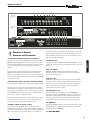
24 25 26 27 28 29 30 31
910 20191817161514
1
1211 2322
21
13
2 3 4 5 6 7 8
ATTAX 100™
Combo
Rear
ATTAX 100 Head Rear
32
ATTAX 100™
Combo/Head
Front

ATTAX 100™ Manual
Use jack 28, CD/LINE INPUT, to patch in any type of line signal. For
example, you could plug in a CD player to play along with a recorded
track. Use a cord equipped with stereo 1/4" jack plugs to do this.
Adjust the level using knob 22, MASTER VOLUME.
1.8 FX SEND/RETURN
Connect an effect device’s output to jack 29, FX RETURN; connect an
effect device’s input to jack 30, FX SEND. The effects loop is a serial
circuit, so adjust the effect amount (or wet-to-dry balance) at the effect
device. The entire preamp signal is routed through the inserted effector
and processed there. Please note that your rig’s sound quality depends
to a considerable extent on the quality of the employed effect device.
A poor-quality signal processor can have an adverse effect on the
ATTAX 100’s sound quality.
• Use high-quality patch cords only to prevent signal loss,
background noise and drop-outs.
• Ensure that the effect device is not being overdriven. Be sure
to keep an eye on whatever type of level meter, gain indicator
or overload lamp the effects device is equipped with, and
adjust its input and output controls accordingly.
• Fuzz boxes, overdrives and distortion units don’t belong in an
FX loop. Plug them into the amp’s input.
1.9 FOOTSWITCH
Your ATTAX 100™ comes with a four-way footswitch that plugs into
jack 31. The buttons on the footswitch correspond to buttons 1 to 4 on
the ATTAX 100’s front panel. When the footswitch is plugged into the
amp, buttons 1 to 4 serve display purposes only, and the footswitch
switches channels.
1.10 FX ON/OFF
Especially for live performances, the ATTAX 100™ enables you to
turn the internal effects on and off individually, in addition to the 4
switchable channels. To do this, you need to connect a footswitch to
the stereo 32 FX ON/OFF jack. Using a simple footswitch (such as the
Hughes & Kettner® FS-1) will enable you to switch the modulation ef-
fects and DELAY at the same time, leaving REVERB unaffected. You can
use a double footswitch (such as the Hughes & Kettner® FS-2) to switch
the modulation effects and DELAY, and REVERB seperately.
1.11 FX-ON/OFF Programming
The switching function of the stereo socket FX-ON/OFF on the back of
the ATTAX 100 can be programmed by turning the MOD FX knob and
holding CLEAN and LEAD pressed down. The following configurations
show which effects blocks are assigned in this way to switch 1 and
switch 2 of the double foot switch:
1) MOD FX knob is in 6 −9 o‘clcok position
switch 1: MOD+DLY, switch 2: REV (factory preset)
2) MOD FX knob is in 9 −12 o‘clcok position
switch 1: MOD, switch 2: DLY (reverb is not connected)
3) MOD FX knob is in 12 −15 o‘clcok position
switch 1: MOD, switch 2: DLY + REV
4) MOD FX knob is in 15 −18 o‘clcok position
switch 1: MOD+DLY+REV, switch 2 remains free (as “global bypass
when single footswitch is used”)
After switching-on, the ATTAX 100 confirms the selected configuration
by making all four channel selecting switches blink on and off a
corresponding number of times. For example, once for combination 1,
and twice for combination 2, etc.. As soon as the LEDs are flashing, you
can let go of CLEAN and LEAD.
ATTENTION: If CLEAN and ULTRA are kept pressed down at the same
time, the entire AMP (all sounds and the FX-ON/OFF configuration) is
reset to the factory presets.
2
The ATTAX 100’s four Channels
2.1 CLEAN
The Clean channel is tweaked to sound sweet when driven by single-
coil as well as humbucking pickups.
2.1.1 CLEAN VOL
Adjusts the CLEAN channel’s volume level. Players who opt for this
class of amp demand a clean channel with enough head-room to
ensure it remains clean. This amp certainly does that. Depending on
the pickups’ output power, you may also be able to dial in a touch of
grit. For single-coils, we recommend that you turn the knob well up.
Do this, and the amp will reward you with tight & punchy midrange
response that is both crisp and fat. If your axe sports humbuckers, set
this knob somewhere around the 12 o‘clock position for crystal-clear
clean tone.
2.1.2 Clean Voicing Section: BASS, MID and TREBLE
knobs. MID and TREBLE controls influence each other, as is standard
and desirable in the tube amps that this voicing section is patterned
on. If you boost the high end, mids are cut and vice versa. This
sound-shaping feature lets you to dial in a wide variety of subtle tonal
variations. We recommend that you go easy on the bass for the CLEAN
channel. Generally, the more mids you dial in, the more assertive your
clean tone in the band’s soundscape. Note that the TREBLE knob shapes
your guitar signal’s bell-like overtones.
2.2 CRUNCH
Overdriven sounds à la carte! This channel covers a diverse tonal
spectrum ranging from squeaky clean to gritty overdrive. It responds
to every nuance in your picking attack, granting you precise control
over the amount of overdrive via your guitar‘s volume knob. Higher
CRUNCH knob settings elicit warm sustain that is ideal for singing leads
with breathy dynamics.
2.2.1 CRUNCH GAIN
Controls the CRUNCH channel’s input sensitivity and thus the amount
of saturation. You can dial in anything from tone that is just sweet
enough to pass for clean to throaty tones that are distinctly rough
around the edges. Again, crank the knob for single-coils; back it off a
bit for humbuckers.
10

ATTAX 100™ Manual
english
2.2.2 CRUNCH VOL
Controls the CRUNCH channel’s level; use it to determine the balance
between it and the other channels.
2.3 LEAD
Yields hard-hitting, snarling British rock tone.
2.3.1 LEAD/ULTRA GAIN
Controls the LEAD and ULTRA channel’s input sensitivity and thus
the amount of saturation, with distortion option ranges from creamy
smooth to British grit and chunky NuMetal thunder.
2.3.2 LEAD Vol
Controls the LEAD channel’s level; use it to determine the balance
between it and the other channels.
2.4 ULTRA
Beware! The ATTAX 100’s heart of darkness, this channel offers fierce
high-gain sounds of a flavor favored by popular NuMetal bands. This
brand of distortion is best described as an angry roar. Depending on
this channel’s settings, you can dial monster NuMetal tone, grinding
post-grunge and alternative sounds, and thunderous death and Gothic
metal noise.
2.4.1 ULTRA VOL
Controls the ULTRA channel’s level; use it to determine the balance
between it and the other channels.
2.5 CRUNCH, LEAD, ULTRA Voicing Section
For handling ease, the ATTAX 100’s three overdrive channels share
common voicing controls. However, behind these tone controls are
three different EQ circuits that are automatically switched along with
the channel. This is why an EQ setting that you have dialed in for the
LEAD channel works so well with the CRUNCH and ULTRA channels.
3
The ATTAX 100’s Effects
The ATTAX 100 features three independent effects - modulation, DELAY
and REVERB. All three effect models may be used simultaneously and
adjusted independently. The FX MATRIX automatically stores settings
for each channel.
3.1 MOD FX
The ATTAX 100 puts at your disposal the three most sought-after
modulation effects: A CHORUS, FLANGER and TREMOLO are all
assigned to one knob. CHORUS is assigned to the first third of the
knob’s control range, FLANGER to the second, and TREMOLO to the
final third. You can sweep the knob within each third to adjust the
effect’s characteristics. We staked out the parameters so that you can
swiftly and easily dial in settings that elicit good-sounding, useful
variations of the desired effect. To switch off modulation effects, simply
twist the knob to the far left. Twisting the knob clockwise adjust the
modulation effect’s rate. Modulation depth is adjusted automatically
according to the rate setting so that every knob position yields a hip
effect sound offering real-world utility.
3.1.1 CHORUS
Low CHORUS settings yield a slow throb for thick, underwater sounds
that work great with ballads. Courtesy of automatic effect depth
adjustment, higher CHORUS settings do not evoke that dreaded
“seasick” tone.
3.1.2 FLANGER
Slow FLANGER settings yield a stately sweeping whoosh effect, while
faster settings give you swirly effects often heard in contemporary rock
and pop tunes.
3.1.3 TREMOLO
Though the classic TREMOLO effect is great for recreating the sounds
of ‘60s, it also serves up some hip effects that work wonders for
contemporary tunes.
3.2 DELAY
DELAY is controlled via two knobs: TIME is an infinitely variable knob
that sweeps smoothly to the next repetition from 80 ms
to 1400 ms. Feedback is adjusted accordingly and automatically.
Short DELAYs with minimal feedback conjure great slap-back rockabilly
sounds, while medium-length DELAYs are perfect for
U2-style jangle. Long DELAY times let you come up with cascading,
Queen-style licks. The VOLUME knob determines the level of
repetitions, with a control range sweeping from off to as loud as the
original signal.
3.3 REVERB
The REVERB is an authentic-sounding emulation of a classic spring
reverb. It handles and responds just like the original: Simply twist the
REVERB knob to adjust the spring REVERB’s volume.
11

ATTAX 100™ Manual
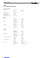
4
Technical Specifications
Safety-related Data
Primary fuses: 220 – 230 V T 1.25 A
120 V T 2.5 A
100 V T 3.15 A
Secondary fuses: T 2.5 A (2 each)
Max. power consumption: 300 watts
Continuous power: 100 watts
Minimum impedance: 4 ohms
Operational temperature range: -10°C – +35°C
Inputs
INPUT: Jack type: 1/4"
Input impedance: 1 Mohms
Sensitivity: - 16 dBV
Max. input level: + 4 dBV
FX Return: Jack type: 1/4"
Input impedance: 6 Kohms
Sensitivity: + 3 dBV
Max. input level: + 14 dBV
CD INPUT: Jack type: 1/4“
Input impedance 22 Kohms
Sensitivity: - 2 dBV
Max. input level: + 14 dBV
Outputs
FX Send: Jack type: 1/4"
Output impedance: 500 ohms
Output level: 3 dBV
Max. output level: + 10 dBV
LINE Output: Jack type: 1/4"
Output impedance: 220 ohms
Output level: 6 dBV
Max. output level: + 20 dBV
External Speaker ATTAX 100: Jack type: 1/4"
Circuit: parallel
Impedance: 8 to 16 ohms
Speakers: (HEAD only) Jack type: Two 1/4"
Circuit: parallel
Impedance: 1x4 to 2x16 ohms
Headphones: Jack type: 1/4" stereo
Output impedance: 550 ohms
Output level: 100 mW an 4 - 600 ohms
12

english español
IMPORTANT ADVICE ON SAFETY! PLEASE
READ BEFORE USE AND KEEP FOR LATER
USE!
• The unit has been built by Hughes & Kettner in accordance with IEC 60065 and left the
factory in safe working order. To maintain this condition and ensure non-risk operation, the
user must follow the advice and warning comments found in the operating instructions. The
unit conforms to Protection Class 1 (protectively earthed).
HUGHES & KETTNER ONLY GUARANTEES THE SAFETY, RELIABILITY AND EFFICIENCY OF THE
UNIT IF:
• Assembly, extension, re-adjustment, modifications or repairs are carried out by Hughes &
Kettner or by persons authorized to do so.
• The electrical installation of the relevant area complies with the requirements of IEC (ANSI)
specifications.
• The unit is used in accordance with the operating instructions.
• The unit is regularly checked and tested for electrical safety by a competent technician.
WARNING:
• If covers are opened or sections of casing are removed, except where this can be done
manually, live parts can become exposed.
• If it is necessary to open the unit this must be isolated from all power sources. Please take
this into account before carrying out adjustments, maintenance, repairs and before replacing
parts.
• The appliance can only be insulated from all power sources if the mains connection is
unplugged.
• Adjustment, maintenance and repairs carried out when the unit has been opened and is still
live may only be performed by specialist personnel who are authorized by the manufacturer
(in accordance with VBG 4) and who are aware of the associated hazards.
• Loudspeaker outputs which have the IEC 417/5036 symbol (Diagram 1, below) can carry
voltages which are hazardous if they are made contact with. Before the unit is switched on,
the loudspeaker should therefore only be connected using the lead recommended by the
manufacturer.
• Where possible, all plugs on connection cables must be screwed or locked onto the casing.
• Replace fuses only with IEC 127 type and specified rating.
• It is not permitted to use repaired fuses or to short-circuit the fuse holder.
• Never interrupt the protective conductor connection.
• Surfaces which are equipped with the „HOT“ mark (Diagram 2, below), rear panels or covers
with cooling slits, cooling bodies and their covers, as well as tubes and their covers are
purposely designed to dissipate high temperatures and should therefore not be touched.
• High loudspeaker levels can cause permanent hearing damage. You should therefore avoid
the direct vicinity of loudspeakers operating at high levels. Wear hearing protection if
continuously exposed to high levels.
MAINS CONNECTION:
• The unit is designed for continuous operation.
• The set operating voltage must match the local mains supply voltage.
• Caution: The unit mains switch must be in position OFF before the mains cable is connected.
• The unit is connected to the mains via the supplied power unit or power cable.
• Power unit: Never use a damaged connection lead. Any damage must be rectified by a
competent technician.
• Avoid connection to the mains supply in distributor boxes together with several other power
consumers.
• The plug socket for the power supply must be positioned near the unit and must be easily
accessible.
PLACE OF INSTALLATION:
• The unit should stand only on a clean, horizontal working surface.
• The unit must not be exposed to vibrations during operation.
• Place the product always in a way that the mains switch is easily accessible.
• Keep away from moisture and dust where possible.
• Do not place the unit near water, baths, wash basins, kitchen sinks, wet areas, swimming
pools or damp rooms. Do not place objects containing liquid on the unit - vases, glasses,
bottles etc.
• Ensure that the unit is well ventilated.
• Any ventilation openings must never be blocked or covered. The unit must be positioned at
least 20 cm away from walls. The unit may only be fitted in a rack if adequate ventilation is
ensured and if the manufacturer’s installation instructions are followed.
• Keep away from direct sunlight and the immediate vicinity of heating elements and radiant
heaters or similar devices.
• If the unit is suddenly moved from a cold to a warm location, condensation can form inside
it. This must be taken into account particularly in the case of tube units. Before switching on,
wait until the unit has reached room temperature.
• Accessories: Do not place the unit on an unsteady trolley, stand, tripod, base or table. If the
unit falls down, it can cause personal injury and itself become damaged. Use the unit only
with the trolley, rack stand, tripod or base recommended by the manufacturer or purchased
together with the unit. When setting the unit up, all the manufacturer’s instructions must be
followed and the setup accessories recommended by the manufacturer must be used. Any
combination of unit and stand must be moved carefully. A sudden stop, excessive use of force
and uneven floors can cause the combination of unit and stand to tip over.
• Additional equipment: Never use additional equipment which has not been recommended
by the manufacturer as this can cause accidents.
• To protect the unit during bad weather or when left unattended for prolonged periods, the
mains plug should be disconnected. This prevents the unit being damaged by lightning and
power surges in the AC mains supply.
Diagram 1 Diagram 2
¡INDICACIONES DE SEGURIDAD
IMPORTANTES!
¡LÉANSE ANTES DE UTILIZAR EL APARATO Y
GUARDENSE PARA SU USO POSTERIOR!
• El aparato ha sido producido por Hughes & Kettner según el IEC 60065 y salió de la
fábrica en un estado técnicamente perfecto. Para conservar este estado y asegurar un
funcionamiento sin peligros el usuario debe tener en cuenta las indicaciones y advertencias
contenidas en las instrucciones de manejo. El aparato corresponde a la clase de protección l
(toma de tierra protegida).
• LA SEGURIDAD, LA FIABILIDAD Y EL RENDIMIENTO DEL APARATO SOLO ESTAN
GARANTIZADOS POR HUGHES & KETTNER CUANDO:
• el montaje, la ampliación, el reajuste, los cambios o las reparaciones se realicen por Hughes
& Kettner o por personas autorizadas para ello;
• la instalación eléctrica del recinto en cuestión corresponda a los requisitos de la
determinación del IEC (ANSI);
• el aparato se use de acuerdo con las indicaciones de uso.
ADVERTENCIA:
• Si se destapan protecciones o se retiran piezas de la carcasa, exceptuando si se puede hacer
manualmente, se pueden dejar piezas al descubierto que sean conductoras de tensión.
• Si es necesario abrir el aparato, éste tiene que estar aislado de todas las fuentes de
alimentación. Esto se debe tener en cuenta antes del ajuste, de un entretenimiento, de una
reparación y de una sustitución de las piezas.
• Un ajuste, un entretenimiento o una reparación en el aparato abierto y bajo tensión sólo
puede ser llevado a cabo por un especialista autorizado por el productor (según VBG 4) que
conozca a fondo los peligros que ello conlleva.
• Las salidas de altavoces que estén provistas de la característica IEC 417/5036 (figura 1, véase
abajo) pueden conducir tensiones peligrosas al contacto. Por ello es indispensable que antes
de poner en marcha el aparato; la conexión se haya realizado únicamente con el cable de
empalmes recomendado por el productor.
• Las clavijas de contacto al final de los cables conectores tienen que estar atornilladas o
enclavadas a la carcasa, en tanto que sea posible.
• Sólo se pueden utilizar del tipo IEC 127 con la intensidad de corriente nominal indicada.
• El empalme del conductor de protección no se puede interrumpir en ningún caso.
• Las superficies provistas de la característica „HOT“ (figura 2, véase abajo), los paneles de
fondo trasero o las protecciones con ranuras de ventilación, los cuerpos de ventilación y
sus protecciones, así como las válvulas electrónicas y sus protecciones pueden alcanzar
temperaturas muy altas durante el funcionamiento y por ello no se deberían tocar.
• Niveles elevados de la intensidad de sonido pueden causar continuos daños auditivos; por
ello debe evitar acercarse demasiado a altavoces que funcionen a altos niveles. En tales
casos utilice protecciones auditivas.
ACOMETIDA A LA RED:
• El aparato está proyectado para un funcionamiento continuo.
• La tensión de funcionamiento ajustada tiene que coincidir con la tensión de la red del lugar.
• Advertencia: el interruptor de la red del aparato tiene que estar en la posición OFF cuando se
conecte el cable de red.
• La conexión a la red eléctrica se efectuará con la fuente de alimentación o con el cable de
red que se entreguen con el aparato.
• Fuente de alimentación: una linea de conexión dañada no se puede sustituir. La fuente de
alimentación no puede volver a ponerse en funcionamiento.
• Evite una conexión de la red eléctrica a distribuidores con muchas tomas de corriente.
• El enchufe para el suministro de corriente tiene que estar cerca del aparato y ser de fácil
acceso.
SITUACION:
• El aparato debería estar situado en una superficie limpia y totalmente horizontal.
• El aparato no puede estar expuesto a ningún tipo de sacudidas durante su funcionamiento.
• Coloque el dispositivo de forma que el interruptor de la red quede accessible facilmente.
• Se deben evitar la humedad y el polvo.
• El aparato no puede ponerse en funcionamiento cerca del agua, la bañera, el lavamanos,
la pila de la cocina, un recinto con tuberías de agua, la piscina o en habitaciones húmedas.
Tampoco se pueden poner objetos llenos de líquido - jarrones, vasos, botellas, etc. - encima
de él.
• Procure que el aparato tenga suficiente ventilación.
• Las aberturas de ventilación existentes no se deben bloquear ni tapar nunca. El aparato
debe estar situado como mínimo a 20 cm de la pared. El aparato sólo se puede montar en
un rack, si se ha procurado la suficiente ventilación y se han cumplido las indicaciones de
montaje del productor.
• Evite los rayos del sol directos así como la proximidad a radiadores, electro-radiadores o
aparatos similares.
• Si el aparato pasa repentinamente de un lugar frío a otro caliente, se puede condensar
humedad en su interior. Esto se debe tener en cuenta sobretodo en los aparatos con válvulas
electrónicas. Antes de poner en marcha el aparato se debe esperar hasta que éste haya
adquirido la temperatura ambiental.
• Accesorios: el aparato no se puede colocar encima de carros, estantes, trípodes, soportes o
mesas inestables. Si el aparato se cae puede causar daños personales y se puede estropear.
Coloque el aparato sólo en un carro, rack, estante, trípode o soporte recomendado por el
productor o que se le haya vendido junto con el aparato. En la instalación se deben seguir
las indicaciones del productor así como utilizar los accesorios recomendados por el mismo
para colocarlo encima. El conjunto del aparato con el pedestal se debe mover con mucho
cuidado. Un paro brusco, la aplicación de una fuerza desmesurada o un suelo irregular puede
ocasionar la caida de todo el conjunto.
• Piezas adicionales: no utilice nunca piezas adicionales que no estén recomendadas por el
productor, ya que se podrían provocar accidentes.
• Para protejer el aparato de una tormenta o si no se supervisa ni utiliza durante algún tiempo,
se debería desconectar la clavija de la red. Así se evitan daños en el aparato a causa de un
rayo y golpes de tensión en la red de corriente alterna.
Figura 1 Figura 2

francais italano
CONSEILS DE SECURITE IMPORTANTS!
PRIERE DE LIRE AVANT L’EMPLOI ET A
CONSERVER POUR UTILISATION ULTERIEURE!
• L’appareil a été conçu par Hughes & Kettner selon la norme IEC 60065 et a quitté
l’entreprise dans un état irréprochable. Afin de conserver cet état et d’assurer un
fonctionnement sans danger de l’appareil nous conseillons à l’utilisateur la lecture des
indications de sécurité contenues dans le mode d’emploi. L’appareil est conforme à la
classification I (mise à terre de protection).
• SURETE, FIABILITE ET EFFICACITE DE L’APPAREIL NE SONT GARANTIS PAR HUGHES &
KETTNER QUE SI:
• Montage, extension, nouveau réglage, modification ou réparation sont effectués par
Hughes & Kettner ou par toute personne autorisée par Hughes & Kettner.
• L’installation électrique de la pièce concernée correspond aux normes IEC (ANSI).
• L’utilisation de l’appareil suit le mode d’emploi.
AVERTISSEMENT
• A moins que cela ne soit manuellement possible, tout enlèvement ou ouverture du boîtier
peut entrainer la mise au jour de pieces sous tension.
• Si l’ouverture de l’appareil est nécessaire, celui-ci doit être coupé de chaque source de
courant. Ceci est à prendre en considération avant tout ajustement, entretien, réparation ou
changement de pieces.
• Ajustement, entretien ou réparation sur l’appareil ouvert et sous tension ne peuvent être
éffectués que par un spécialiste autorisé par le fabricant (selon VBG4). Le spécialiste étant
conscient des dangers liés à ce genre de réparation.
• Les sorties de baffles qui portent le signe IEC 417/5036 (fig. 1, voir en bas) peuvent être
sous tension dangereuse. Avant de brancher l’appareil utiliser uniquement le câble de
raccordement conseillé par le fabricant pour raccorder les baffles.
• Toutes les prises des câbles de raccordement doivent être, si possible, vissées ou verrouillées
sur le boîtier.
• L’utilisation de fusibles rafistolés ou court-circuites est inadmissible.
• Ne jamais interrompre la connexion du circuit protecteur.
• Il est conseillé de ne pas toucher aux surfaces pourvues du signe „HOT“ (fig. 2, voir en bas),
aux parois arrières ou caches munis de fentes d’aération, éléments d’aération et leurs caches
ansi qu’aux tubes et leurs caches. Ces éléments pouvant atteindre des températures élévées
pendant l’utilisation de l’appareil.
• Les Niveaux de puissance élévés peuvent entrainer des lésions auditives durables. Evitez
donc la proximité de haut-parleurs utilisés à haute puissance. Lors de haute puissance
continue utilisez une protection auditive.
BRANCHEMENT SUR LE SECTEUR
• L’appareil est conçu pour une utilisation continue.
• La tension de fonctionnement doit concorder avec la tension secteur locale.
• Attention: L’interrupteur de secteur de l’appareil doit être sur la position OFF, lorsque le
câble de réseau est raccordé.
• Le raccordement au réseau éléctrique s’effectue avec l’adaptateur ou le cordon
d´alimentation livré avec l’appareil.
• Adaptateur: Un câble de raccordement abimé ne peut être remplacé. L’adaptateur est
inutilisable.
• Evitez un raccordement au réseau par des boîtes de distribution surchargées.
• La prise de courant doit être placée à proximité de l’appareil et facile à atteindre.
LIEU D’INSTALLATION
• L’appareil doit être placé sur une surface de travail propre et horizontale.
• L’appareil en marche ne doit en aucun cas subir des vibrations.
• Posez l´appareil en place de sorte que l´interrupteur du réseau reste accessible facilement.
• Evitez dans la mesure du possible poussière et humidité.
• L’appareil ne doit pas être placé à proximité d’eau, de baignoire, lavabo, évier, pièce d’eau,
piscine ou dans une pièce humide. Ne placez aucun vase, verre, bouteille ou tout objet
rempli de liquide sur l’appareil.
• L’appareil doit être suffisamment aéré.
• Ne jamais recouvrir les ouvertures d’aération. L’appareil doit être placé à 20 cm du mur au
minimum. L’appareil peut être monté dans un Rack si une ventilation suffisante est possible
et si les conseils de montage du fabricant sont suivis.
• Evitez les rayons de soleil et la proximité de radiateurs, chauffages etc.
• Une condensation d’eau peut se former dans l’appareil si celui-ci est transporté brusquement
d’un endroit froid à un endroit chaud. Ceci est particulièrement important pour des appareils
à tubes. Avant de brancher l’appareil attendre qu’il ait la température ambiante.
• Accessoires: L’appareil ne doit être placé sur un chariot, support, trépied, bâti ou table
instable. Une chute de l’appareil peut entrainer aussi bien des dommages corporels que
techniques. Utilisez l’appareil uniquement avec un chariot, Rack, support, trépied ou bâti
conseillé par le fabricant ou vendu en combinaison avec l’appareil. Les indications du
fabricant pour l’installation de l’appareil sont à suivre, et les accessoires d’installation
conseillés par le fabricant sont à utiliser. Un ensemble support et appareil doit être déplacé
avec précaution. Des mouvements brusques et des revêtements de sol irreguliers peuvent
entrainer la chute de l´ensemble.
• Equipements supplémentaires: Ne jamais utiliser un équipement supplémentaire n’ayant pas
été conseillé par le fabricant, ceci pouvant entrainer des accidents.
• Afin de protéger l’appareil pendant un orage ou s’il ne doit pas être utilisé pendant un
certain temps, il est conseillé d’enlever la prise au secteur. Ceci évite des dommages dûs à
la foudre ou à des coups de tension dans le réseau à courant alternatif.
Fig. 1 Fig. 2
IMPORTANTI AVVERTIMENTI DI SICUREZZA!
LEGGERE ATTENTAMENTE PRIMA DELL’USO E
CONSERVARE PER UN UTILIZZO SUCCESSIVO
• L’apparecchio è stato costruito dalla Hughes & Kettner secondo la normativa europea IEC
60065 ed ha lasciato il nostro stabilimento in stato ineccepibile. Per garantire il mantenimento
di tale stato e un utilizzo assolutamente privo di rischi l’utente è tenuto ad osservare le
indicazioni e gli avvertimenti di sicurezza contenuti nelle istruzioni per l’uso. L’apparecchio
rispecchia il livello di sicurezza I (collegato a terra).
• Sicurezza, affidabilità e prestazioni dell’apparecchio vengono garantiti dalla Hughes & Kettner
solo ed esclusivamente se:
• Montaggio, ampliamento, rimessa a punto, modifiche e riparazioni vengono eseguite dalla
Hughes & Kettner stessa o da personale da essa autorizzato.
• Gli impianti elettrici nei locali prescelti per l’uso dell’apparecchio rispondono alle normative
stabilite dall’ANSI.
• L’apparecchio viene utilizzato come indicato nel libretto delle istruzioni per l’uso.
Avvertimenti:
• In caso di apertura di parti di rivestimento o rimozione di parti dell’involucro, a meno
che non si tratti di pezzi rimovibili semplicemente a mano, possono venire alla luce parti
dell’apparecchio conduttrici di tensione.
• Se l’apertura dell’apparecchio dovesse risultare necessaria è indispensabile staccare
precedentemente quest’ultimo da tutte le fonti di tensione. Rispettare tale misura di
prevenzione anche prima di un allineamento, di operazioni di manutenzione, della messa in
esercizio o della sostituzione di componenti all’interno dell’apparecchio.
• Allineamento, operazioni di manutenzione o eventuali riparazioni dell’apparecchio in
presenza di tensione vanno eseguite esclusivamente da personale specializzato ed
autorizzato, in grado di eseguire tali operazioni evitandone i rischi connessi.
• Le uscite degli altoparlanti contrassegnate dai caratteri IEC 417/5036 (vedi illustrazione 1 a
fondo pag.) possono essere conduttrici di tensione pericolosa con cui evitare il contatto. Per
questo motivo, prima di accendere l’apparecchio, collegare quest’ultimo agli altoparlanti
servendosi esclusivamente del cavetto d’allacciamento indicato dal produttore.
• Tutte le spine e i cavi di collegamento devono essere avvitati o fissati all’involucro
dell’apparecchio per quanto possibile.
• Utilizzare esclusivamente fusibili del tipo IEC 127 con la indicata corrente nominale.
• L’utilizzo di fusibili di sicurezza non integri e la messa in corto circuito del sostegno di metallo
sono proibite.
• Non interrompere mai il collegamento con il circuito di protezione.
• Superfici contrassegnate dalla parola „HOT“ (vedi illustrazione 2 a fondo pag.), cosi come
griglie di aerazione, dispositivi di raffreddamento e i loro rivestimenti di protezione, oppure
valvole e i relativi rivestimenti protettivi possono surriscaldarsi notevolmente durante l’uso e
per questo motivo non vanno toccate.
• L’ascolto di suoni ad alto volume può provocare danni permanenti all’udito. Evitate perciò
la diretta vicinanza con altoparlanti ad alta emissione di suono e utilizzate cuffie protettive in
caso ciò non sia possibile.
Alimentazione:
• L’apparecchio è concepito per il funzionamento continuo.
• La tensione di esercizio deve corrispondere alla tensione di rete a cui ci si allaccia.
• Attenzione: l’interruttore di alimentazione dell’apparecchio deve essere in posizione OFF
quando viene allacciato il cavetto d’alimentazione.
• L’allacciamento alla rete elettrica avviene tramite alimentatore o cavetto d’alimentazione
consegnato insieme all’apparecchio.
• Alimentatore: un cavo di connessione danneggiato non può essere sostituito. L’alimentatore
non può più essere utilizzato.
• Evitate un allacciamento alla rete di corrente utilizzando cassette di distribuzione sovraccariche.
• La spina di corrente deve essere situata nelle vicinanze dell’apparecchio e facilmente
raggiungibile in qualsiasi momento.
Locali di collocamento:
• Opportuno collocare l’apparecchio su una superficie pulita e orizzontale.
• Non sottoporre l’apparecchio in funzione a scosse e vibrazioni.
• L’apparecchio deve essere posizionato sempre in modo da assicurare il libero accesso
all’interruttore di alimentazione.
• Proteggere l’apparecchio per quanto possibile da umidità e polvere.
• Non collocare l’apparecchio vicino ad acqua, vasche da bagno, lavandini, lavelli da cucina,
locali umidi o piscine. Non appoggiare recipienti contenenti liquidi - vasi, bicchieri, bottiglie,
ecc. - sull’apparecchio.
• Provvedere ad una buone aerazione dell’apparecchio.
• Eventuali aperture previste per la ventilazione dell’apparecchio non vanno ne bloccate, ne
mai coperte. L’apparecchio va collocato ad almeno 20 cm di distanza dalle pareti circostanti e
può essere inserito tra altre componenti di un impianto solo in caso di sufficiente ventilazione
e qualora le direttive di montaggio del produttore vengano rispettate.
• Evitare di esporre l’apparecchio ai raggi del sole e di collocarlo direttamente nelle vicinanze
di fonti di calore come caloriferi, stufette, ecc.
• Se l’apparecchio viene trasportato rapidamente da un locale freddo ad uno riscaldato
può succedere che al suo interno si crei della condensa. Ciò va tenuto in considerazione
soprattutto in caso di apparecchi a valvole. Attendere che l’apparecchio abbia assunto la
temperatura ambiente prima di accenderlo.
• Accessori: non collocare l’apparecchio su carrelli, supporti, treppiedi, superfici o tavoli
instabili. Se l’apparecchio dovesse cadere a terra potrebbe causare danni a terzi o
danneggiarsi irreparabilmente. Utilizzate per il collocamento dell’apparecchio supporti,
treppiedi e superfici che siano consigliate dal produttore o direttamente comprese nell’offerta
di vendita. Per il collocamento dell’apparecchio attenetevi strettamente alle istruzioni del
produttore, utilizzando esclusivamente accessori da esso consigliati. L’apparecchio in
combinazione ad un supporto va spostato con molta attenzione. Movimenti bruschi o il
collocamento su pavimenti non piani possono provocare la caduta dell’apparecchio e del suo
supporto.
• Accessori supplementari: non utilizzate mai accessori supplementari che non siano consigliati
dal produttore, potendo essere ciò causa di incidenti.
• Per proteggere l’apparecchio in caso di temporali o nel caso questo non venisse utilizzato per
diverso tempo si consiglia di staccarne la spina di corrente. In questo modo si evitano danni
all’apparecchio dovuti a colpi di fulmine o ad improvvisi aumenti di tensione nel circuito di
corrente alternata.
Illustrazione 1 Illustrazione 2

This is to certify that
HUGHES & KETTNER ATTAX 100™
complies with the provisions of the Directive of the Council
of the European Communities on the approximation of
the laws of the Member States relating to electromagnetic
compatibility (EMC Directive 89/336/EEC) and the
low voltage Directive (73/23/EEC). This declaration of
conformity of the European Communities is the result
of an examination carried out by the Quality Assurance
Department of STAMER GmbH in accordance with European
Standards EN 50081-1, EN 50082-1and EN 60065 for low
voltage, as laid down in Article 10 of the EMC Directive.
Stamer Musikanlagen GmbH*
Magdeburger Str. 8
66606 St.Wendel
Lothar Stamer Dipl.Ing.
Managing Director
St.Wendel, June/2007
Für das folgend bezeichnete Erzeugnis
HUGHES & KETTNER ATTAX 100™
wird hiermit bestätigt, dass es den wesentlichen
Schutzanforderungen entspricht, die in der Richtlinie
des Rates zur Angleichung der Rechtsvorschriften der
Mitgliedsstaaten über die elektromagnetische Verträglichkeit
(89/336/ EWG) und der Niederspannungsrichtlinie
(73/23/EWG) festgelegt sind. Diese Erklärung gilt für alle
Exemplare, und bestätigt die Ergebnisse der Messungen,
die durch die Qualitätssicherung der Fa. Stamer
Musikanlagen GmbH durchgeführt wurden. Zur Beurteilung
des Erzeugnisses hinsichtlich elektromagnetischer
Verträglichkeit wurden folgende Normen herange zogen:
EN 50081-1 • EN 50082-1. Zur Beurteilung der Einhaltung
der Niederspannungsrichtlinie wurde folgende Norm
herangezogen: EN 60065
Diese Erklärung wird verantwortlich für den Hersteller
Stamer Musikanlagen GmbH*
Magdeburger Str. 8
66606 St.Wendel
abgegeben durch
Lothar Stamer Dipl.Ing.
Geschäftsführer
St.Wendel, Juni 2007
31

-
 1
1
-
 2
2
-
 3
3
-
 4
4
-
 5
5
-
 6
6
-
 7
7
-
 8
8
-
 9
9
-
 10
10


Hughes & Kettner ATTAX 100 Head Manuel utilisateur
- Taper
- Manuel utilisateur
- Ce manuel convient également à
dans d''autres langues
Documents connexes
-
Hughes & Kettner Access ATTAX 100 Manuel utilisateur
-
-
-
-
-
Hughes & Kettner 60 DFX Manuel utilisateur
-
-
-
-