Esoteric F-01 Le manuel du propriétaire
- Catégorie
- Équipement musical supplémentaire
- Taper
- Le manuel du propriétaire
Ce manuel convient également à


3
English
IMPORTANT SAFETY INSTRUCTIONS
CAUTION: TO REDUCE THE RISK OF ELECTRIC SHOCK,
DO NOT REMOVE COVER (OR BACK). NO USER-
SERVICEABLE PARTS INSIDE. REFER SERVICING TO
QUALIFIED SERVICE PERSONNEL.
<The lightning flash with arrowhead symbol, within an
equilateral triangle, is intended to alert the user to the
presence of uninsulated “dangerous voltage” within the
product’s enclosure that may be of sufficient magnitude
to constitute a risk of electric shock to persons.
BThe exclamation point within an equilateral triangle is
intended to alert the user to the presence of important
operating and maintenance (servicing) instructions in
the literature accompanying the appliance.
WARNING: TO PREVENT FIRE OR SHOCK HAZARD,
DO NOT EXPOSE THIS APPLIANCE TO RAIN OR
MOISTURE.
CAUTION
oDO NOT REMOVE THE EXTERNAL CASES OR CABINETS TO EXPOSE
THE ELECTRONICS. NO USER SERVICEABLE PARTS ARE INSIDE.
oIF YOU ARE EXPERIENCING PROBLEMS WITH THIS PRODUCT,
CONTACT THE STORE WHERE YOU PURCHASED THE UNIT FOR
A SERVICE REFERRAL. DO NOT USE THE PRODUCT UNTIL IT HAS
BEEN REPAIRED.
oUSE OF CONTROLS OR ADJUSTMENTS OR PERFORMANCE OF
PROCEDURES OTHER THAN THOSE SPECIFIED HEREIN MAY RESULT
IN HAZARDOUS RADIATION EXPOSURE.
1) Read these instructions.
2) Keep these instructions.
3) Heed all warnings.
4) Follow all instructions.
5) Do not use this apparatus near water.
6) Clean only with dry cloth.
7) Do not block any ventilation openings. Install in accordance with
the manufacturer’s instructions.
8) Do not install near any heat sources such as radiators, heat
registers, stoves, or other apparatus (including amplifiers) that
produce heat.
9) Do not defeat the safety purpose of the polarized or grounding-
type plug. A polarized plug has two blades with one wider than
the other. A grounding type plug has two blades and a third
grounding prong. The wide blade or the third prong are provided
for your safety. If the provided plug does not fit into your outlet,
consult an electrician for replacement of the obsolete outlet.
10) Protect the power cord from being walked on or pinched par-
ticularly at plugs, convenience receptacles, and the point where
they exit from the apparatus.
11) Only use attachments/accessories specified by the manufacturer.
12) Use only with the cart, stand, tripod, bracket,
or table specified by the manufacturer, or
sold with the apparatus. When a cart is
used, use caution when moving the cart/
apparatus combination to avoid injury from
tip-over.
13) Unplug this apparatus during lightning storms or when unused
for long periods of time.
14) Refer all servicing to qualified service personnel. Servicing is
required when the apparatus has been damaged in any way,
such as power-supply cord or plug is damaged, liquid has been
spilled or objects have fallen into the apparatus, the apparatus
has been exposed to rain or moisture, does not operate nor-
mally, or has been dropped.
oThe apparatus draws nominal non-operating power from the AC
outlet with its POWER or STANDBY/ON switch not in the ON position.
oThe mains plug is used as the disconnect device; the disconnect
device shall remain readily operable.
oCaution should be taken when using earphones or headphones
with the product because excessive sound pressure (volume) from
earphones or headphones can cause hearing loss.
WARNING
Products with Class ! construction are equipped with a power
supply cord that has a grounding plug. The cord of such a prod-
uct must be plugged into an AC outlet that has a protective
grounding connection.
IN USA/CANADA, USE ONLY ON 120V SUPPLY.

4
IMPORTANT SAFETY INSTRUCTIONS (continued)
CAUTION
oDo not expose this apparatus to drips or splashes.
oDo not place any objects filled with liquids, such as vases, on
the apparatus.
oDo not install this apparatus in a confined space such as a
book case or similar unit.
oThe apparatus should be located close enough to the AC
outlet so that you can easily reach the power cord plug at any
time.
oIf the product uses batteries (including a battery pack or
installed batteries), they should not be exposed to sunshine,
fire or excessive heat.
oCAUTION for products that use replaceable lithium batteries:
there is danger of explosion if a battery is replaced with an
incorrect type of battery. Replace only with the same or equiva-
lent type.
V Precautions concerning batteries
Misuse of batteries could cause them to rupture or leak leading to
fire, injury or the staining of nearby things. Please read and observe
the following precautions carefully.
oBe sure to insert the batteries with correct positive (¥) and nega-
tive (^) orientations.
oUse batteries of the same type. Never use different types of batter-
ies together.
oIf the remote control is not used for a long time (more than a
month), remove the batteries to prevent them from leaking.
oIf the batteries leak, wipe away the leakage inside the battery
compartment and replace the batteries with new ones.
oDo not use batteries of types other than those specified. Do not
mix new batteries with old ones or use different types of batteries
together.
oDo not heat or disassemble batteries. Never throw batteries into
fire or water.
oDo not carry or store batteries with other metallic objects. The bat-
teries could short circuit, leak or explode.
oNever recharge a battery unless it is confirmed to be a recharge-
able type.
oDo not expose batteries to extremely low air pressure as it could
result in an explosion or leakage of flammable liquids or gases.
Supplier’s Declaration of Conformity
Model number: F-01/F-02
Trade name: ESOTERIC
Responsible party: 11 Trading Company, LLC
Address: 3502 Woodview Trace #200 Indianapolis, IN 46268 U.S.A.
URL: https://11tradingcompany.com/contact-us/
This device complies with Part.15 of FCC Rules.
Operation is subject to the following two conditions:
1) This device may not cause harmful interference
2) This device must accept any interference received, including
interference that may cause undesired operation.
Information
This equipment has been tested and found to comply with the
limits for a Class B digital device, pursuant to Part 15 of the FCC
Rules. These limits are designed to provide reasonable protection
against harmful interference in a residential installation. This equip-
ment generates, uses, and can radiate radio frequency energy and,
if not installed and used in accordance with the instructions, may
cause harmful interference to radio communications. However,
there is no guarantee that interference will not occur in a particular
installation. If this equipment does cause harmful interference to
radio or television reception, which can be determined by turning
the equipment off and on, the user is encouraged to try to correct
the interference by one or more of the following measures:
• Reorient or relocate the equipment and/or the receiving antenna.
• Increase the separation between the equipment and receiver.
• Connect the equipment into an outlet on a circuit different from
that to which the receiver is connected.
• Consult the dealer or an experienced radio/TV technician for help.
CAUTION
Changes or modifications not expressly approved by the party
responsible for compliance could void the user’s authority to
operate the equipment.
Model for Canada
This Class B digital apparatus complies with Canadian ICES-003.
Model for Europe
This product complies with the European
Directives request, and the other Commission
Regulations.
Model for UK
This product complies with the applicable UK
regulations.

5
English
ESOTERIC is a trademark of TEAC CORPORATION, registered in the U.S.
and other countries.
Other company names, product names and logos in this document
are the trademarks or registered trademarks of their respective owners.
For European Customers
Disposal of electrical and electronic equipment and
batteries and/or accumulators
a) All electrical/electronic equipment and waste batteries/accu-
mulators should be disposed of separately from the municipal
waste stream via collection facilities designated by the govern-
ment or local authorities.
b) By disposing of electrical/electronic equipment and waste
batteries/accumulators correctly, you will help save valu-
able resources and prevent any potential negative effects on
human health and the environment.
c) Improper disposal of waste electrical/electronic equipment
and batteries/accumulators can have serious effects on the
environment and human health because of the presence of
hazardous substances in the equipment.
d) The Waste Electrical and Electronic Equipment (WEEE)
symbols, which show wheeled bins that have been
crossed out, indicate that electrical/electronic equip-
ment and batteries/accumulators must be collected
and disposed of separately from household waste.
If a battery or accumulator contains more than the
specified values of lead (Pb), mercury (Hg), and/or
cadmium (Cd) as defined in the Battery Directive
(2006/66/EC, 2013/56/EU), then the chemical symbols
for those elements will be indicated beneath the WEEE symbol.
e) Return and collection systems are available to end users. For
more detailed information about the disposal of old electri-
cal/electronic equipment and waste batteries/accumulators,
please contact your city office, waste disposal service or the
shop where you purchased the equipment.
Pb, Hg, Cd

6
Contents
Thank you for purchasing this ESOTERIC product.
In order to provide you with the best audio quality for many years, we
manufacture ESOTERIC products with strict quality control one unit at
a time.
Read this manual carefully to get the best performance from this
product. After reading it, keep it in a safe place with the warranty card
for future reference.
Before use
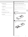
Included accessories
Check to be sure the box includes all the supplied accessories shown
below. Please contact the store where you purchased this product if
any of these accessories are missing or have been damaged during
transportation.
Power cord × 1
Remote control (RC-1339) × 1
Batteries for remote control (AA) × 2
Felt pads × 4
Owner’s manual (this document) × 1
Warranty card × 1
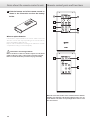
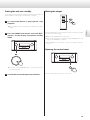
Note about pinpoint feet
High-precision metal pinpoint feet are attached to the bottom plate
of this unit.
The pinpoint feet and their stands are loose, but when the unit is
placed in position, it is supported by these pinpoint feet, which effec-
tively disperse vibrations.
Chassis
Pinpoint foot (metal)
Foot-stand (metal)
After
placement
oIf there is a gap between a chassis and a pinpoint foot after place-
ment, turn the pinpoint foot in the direction that tightens the
screw to eliminate the gap.
oApply the included felt pads to the bottoms of the foot-stands to
avoid scratching the surface where the unit is placed.
oThis unit is very heavy, so take care to avoid injury during installation.
IMPORTANT SAFETY INSTRUCTIONS ................................3
Before use ..........................................................6
Precautions for use .................................................7
Connections ........................................................8
Connecting speakers ..............................................10
Connections for use as a preamp ..................................11
Connecting using ES-LINK Analog .................................12
Connecting headphones ..........................................13
Main unit parts and functions ......................................14
Notes about the remote control ...................................15
Remote control parts and functions. . . . . . . . . . . . . . . . . . . . . . . . . . . . . . . . 16
Basic operation ....................................................18
Settings ...........................................................21
MENU1 ...........................................................22
MENU2 ...........................................................24
MENU3 ...........................................................26
Notes about the protection circuits ................................28
Troubleshooting ...................................................28
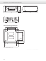
F-01/F-02 specifications. . . . . . . . . . . . . . . . . . . . . . . . . . . . . . . . . . . . . . . . . . . . 29
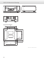
F-01/F-02 dimensional drawings ...................................30

7
English
Precautions for use
Maintenance
Use a soft dry cloth to wipe the surface of the unit clean.
For stubborn smudges, use a damp cloth that has been thoroughly
wrung out to remove excess moisture.
V For safety, disconnect the power plug from the out-
let before cleaning.
oNever spray liquid directly on this unit.
oDo not use chemically-treated wipes, thinner or similar substances
because they could damage the surface of the unit.
oAvoid allowing rubber or plastic materials to touch the unit for
long periods of time because they could damage the cabinet.
oThis equipment is very heavy, so take care to avoid injury when
opening the packaging and when moving it.
oPlace the unit in a stable location near the stereo system that will
be used with it.
oDo not install this unit in a location that could become hot. This
includes places that are exposed to direct sunlight or near a radia-
tor, heater, stove or other heating equipment. Moreover, do not
place it on top of another amplifier or equipment that generates
heat. Doing so could cause discoloration or deformation.
oAvoid locations that are subject to vibrations or exposed to exces-
sive dust, cold or moisture.
oIn order to enable good heat dissipation, leave at least 20cm (8")
between this unit and walls and other equipment when install-
ing it. If you put it in a rack, for example, leave at least 30cm (12")
open above and 20cm (8") open behind it.
Failure to provide these gaps could cause heat to build up inside
and result in fire.
oDo not install the unit face up or on its side.
oDo not place anything, not even CDs, CD-Rs, LP records or cassette
tapes, on top of the unit.
oDo not put cloth on top of the unit or place it on top of bedding
or thick carpet. Doing so could cause it to overheat or damage it.
oDo not move the unit during use.
oSupply voltage to the unit that matches the voltage as printed on
its back. If you are in any doubt regarding this matter, consult an
electrician.
oDo not open the body of the unit as this might result in damage
to the circuitry or cause electric shock. If a foreign object should
get into the unit, contact your dealer.
oWhen removing the power plug from the wall outlet, always pull
directly on the plug; never yank on the cord.
oFor F-01 only:
Since the unit includes a class A amp, there is nothing unusual
about the top of the unit becoming hot, even when using head-
phones or the pre-out.
oIf the unit becomes too hot, the overheating protection circuit
(page28) will activate, so please use care when placing the unit.

8
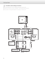
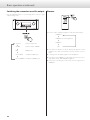
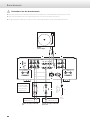
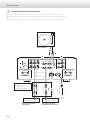
Connections
V Precautions when making connections
oAfter completing all other connections, plug the power plug into a power outlet.
oRead the owner’s manuals of all devices that will be connected, and follow their instructions.
oDo not bundle connecting cables with power cords. Doing so could cause noise.
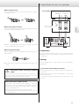
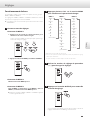
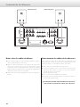
XLR pin assignment
1. COMMON
2. HOT (+)
3. COLD (−)
Included power cord
Record player
RCA cables
XLR cables
Audio output
(AUDIO OUT, etc.)
Audio output
(AUDIO OUT, etc.)
Super Audio CD player,
tuner, etc.
Super Audio CD player, etc.
c
Wall outlet

9
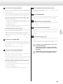
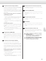
English
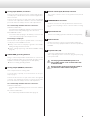
A Analog input (INPUTS) connectors
Connect the analog output connectors of Super Audio CD play-
ers, DVD players, cassette decks, tuners and other equipment to
these connectors.
Connect the R connector of a pair on this unit to the right (R)
connector of an output device and the L connector of the same
pair on this unit to the left (L) connector of the output device.
Use commercially-available cables for connections.
XLR: balanced XLR cables
Insert the balanced XLR plugs until the connector levers lock.
Press these levers and pull the plugs out to disconnect.
RCA, PHONO: RCA cables
Connect the white pin plugs to the white (L) connectors and
connect the red pin plugs to the red (R) connectors.
Connecting record players
This unit has a built-in phono equalizer. When connecting a
record player, use the PHONO connectors.
oAlways connect the record player’s ground to the SIGNAL
GND grounding terminal on this unit.
oSet the cartridge type being used with the PHONO> setting
(page26).
B SIGNAL GND grounding terminal
Using a commercially-available sheathed wire to connect this
to the grounding terminal of a Super Audio CD player, power
amplifier or other device might improve the audio quality.
oThis is not a safety grounding terminal.
C Analog output (PRE OUT) connectors
These output 2 channels of analog audio.
To use this unit as a preamp, see “Connections for use as a pre-
amp” on page11.
Connect the R connector of a pair on this unit to the right (R)
connector of an input device and the L connector of the same
pair on this unit to the left (L) connector of the input device.
Use commercially-available cables for connections.
XLR: balanced XLR cables
Insert the balanced XLR plugs into the connectors until they
lock.
ESL-A: balanced XLR cables
Use commercially-available shielded cables (page12).
D Remote control input (RS-232C) connector
This control connector is for use by professionals (custom
installers).
E TRIGGER IN/OUT connectors
Use these connectors to control power from an external source.
Do not connect anything to these connectors when not using
them.
F Optional board slot
This slot is for installing optional boards that are sold separately.
G DC IN connector
Use this connector to connect an external power supply unit.
Do not connect any equipment that has not been specified by
ESOTERIC.
H AC power inlet (~IN)
Connect the supplied power cord to this AC inlet.
After completing all other connections, plug the power plug
into a power outlet.
VUse only a genuine ESOTERIC power cord.
Use of other power cords could result in fire
or electric shock.
VDisconnect the power plug from the outlet if
you will not use the unit for a long time.

10
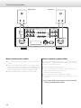
Connecting speakers
Notes about speaker cables
oUse commercially-available speaker cables to connect the
speakers.
oUse the shortest speaker cables possible. The longer the cable, the
greater the resistance value and the more that damping perfor-
mance is reduced. Moreover, length also increases inductance and
capacitance, degrading the sound quality of high frequencies.
oUse left and right speaker cables that have the same length.
How to connect speaker cables
Use commercially-available speaker cables to connect the + terminal
of the unit to the + terminal of the speaker and the − terminal of the
unit to the − terminal of the speaker.
oUse speakers with at least 4Ω impedance.
oIf the exposed tip of the core wire of a speaker cable contacts
another cord or terminal, a short could occur.
Never allow a speaker cable to short.
oDo not connect more than one amplifier to a speaker.
oDo not bundle speaker cables with power cords. Doing so could
cause noise.
VThe power plug should always be disconnected
when connecting speaker cables.
Right speaker Left speaker

11
English
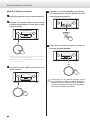
When using bare wires
Loosen the cap and insert the core wire into the hole in the terminal.
Then, tighten the cap.
When using spade connectors
Loosen the cap and insert the spade connector between the cap and
base of the terminal. Then, tighten the cap.
oWhen connecting speakers with spade connectors, they should
have inside diameters of at least 8mm.
When using banana plugs
With the cap tightened, insert the plug into the opening in the end
of the terminal.
oCarefully read the instructions for the banana plugs that you are
using.
VPrecautions when connecting speaker
cables
Connect the cables securely so that they do not become loose
and the core wires or terminals at their ends do not become
exposed and contact other metal parts or the unit.
Notice about the European model
In accordance with European safety regulations, connecting
banana plugs to speaker terminals is not allowed on European
models. The holes into which banana plugs could be inserted have
been covered with black caps.
Connect speakers using bare wires or spade connectors.
If a black cap should become separated from its terminal, return it
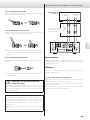
to its original position.
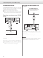
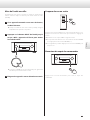
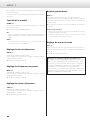
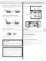
Connections for use as a preamp
Power amplifier
Connect using a set
of only one type.
XLR cables
Audio input
AUDIO IN
ES-LINK Analog
input connectors
ESL-A
Connections
Use commercially-available XLR cables to connect the analog output
(PRE OUT) connectors on this unit to the analog input connectors on
the power amp.
Settings
Press the OUTPUT button to set the output connectors to SP+PRE or
PRE (page20).
VPrecautions when making connections
After completing all other connections, plug the power plug into a
power outlet.
Read the owner’s manuals of all devices that will be connected, and
follow their instructions.
Do not bundle connecting cables with power cords. Doing so could
cause noise.

12
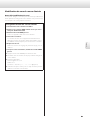
Connecting using ES-LINK Analog
ES-LINK Analog overview
The current transmission method utilizes the performance of HCLD
buffer circuits that feature the ability to supply strong current at high
speed. This suppresses the impact of impedance on signal paths,
enabling pure and powerful transmission of signals.
oUse connection cables that are shielded and balanced.
oOrdinary balanced cables (with XLR connectors) are used for
connection. These connectors can only be used with compatible
devices, however, because the transmission format is unique.
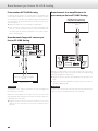
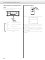
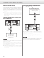
Connecting source devices using ES-LINK
Analog
Source device
XLR cables
Analog audio output (ESL-A)
connectors
ATTENTION
Set the analog output setting to ESLA on the source device before
connecting it.
Use XLR cables to connect the analog audio output (ESL-A) con-
nectors on the source device to the analog audio input (ESL-A)
connectors on this unit.
oSet the operation mode to ESLA for the input connectors on this
unit that are connected to the source device (page26).
Connecting to a power amplifier using
ES-LINK Analog
XLR cables
ES-LINK Analog input (ESL-A)
connectors
Power amplifier that supports
ES-LINK Analog
Use XLR cables to connect the analog audio output (ESL-A) connec-
tors on this unit to the ES-LINK Analog input (ESL-A) connectors on
the power amplifier.
oSet the power amplifier input selector to ESLA.
oPress the OUTPUT button to set the output connectors to SP+PRE
or PRE (page20).
ATTENTION
The ESL-A output connectors of this unit are female-type connectors
to prevent accidental connection with XLR output connectors.

13
English
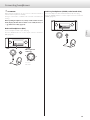
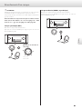
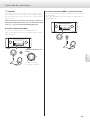
Connecting headphones
VATTENTION
While wearing headphones, do not connect or disconnect them or
turn the unit on or put it into standby.
Doing so could result in a sudden loud noise that could harm your
hearing.
Before putting headphones on, always set the volume to mini-
mum (display should show “0” when set to “STEP (0–99.9)” or
“− ” when set to “dB”) (page18).
Balanced headphones (BAL)
Connect headphones with a 4-pin XLR plug.
Press the OUTPUT button to set the output connector to Phones
(BAL) (page20).
PIN assignments
of this unit
1
23
4
1: L+, 2: L−
3: R+, 4: R−
Ordinary headphones (UNBAL, unbalanced drive)
Connect headphones with a standard 6.3mm (1/4") stereo plug.
Press the OUTPUT button to set the output connector to Phones
(UNBAL) (page20).

14
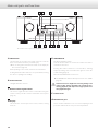
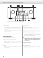
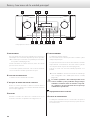
Main unit parts and functions
A INPUT knob
Turn this knob to select the active input. Select the connector
that is connected to the device you want to play.
oYou can change the names that are shown on the display for
the connectors (page23).
When inputting a source name, use this to select characters.
Holding this down makes it function as a power button, turning
the unit on or putting it into standby.
B Power indicator
This lights when the unit is on.
C Remote control signal receiver
This receives signals from the remote control. When using the
remote control, point the end of it toward this receiver panel
(page15).
D Display
This shows the current input source name, volume, setting
items, etc.
E VOLUME knob
Use this to adjust the volume.
Turn this knob clockwise to increase the volume and counter-
clockwise to decrease it.
Pressing this makes it function as a mute button, enabling
temporary muting of the sound. Press this again to restore the
volume setting (page19).
When muted, “MUTE” blinks on the screen.
oThe VOLUME knob will not affect input sources set to THRU>
(page26).
VSudden loud noises might cause hearing damage and
other trouble. Always minimize the volume before
starting playback, and adjust it to an appropriate level
after playback begins.
F Control cover
G Maintenance port
This is used for maintenance. Do not connect anything to this
port unless instructed to do so by our service department.
The control cover is open in the illustration above.

15
English
H Headphones jacks
Connect headphones plugs (standard 6.3mm (1/4") stereo or
4-pin XLR) here (page13).
I OUTPUT button
Press this to switch which connector outputs analog audio
(page20).
Press this when in setting mode to return the display to normal.
J MENU button
Press this to enter setting mode.
K Setting adjustment (l/;) buttons
Use these to change setting values when in setting mode.
L Open button
Press this to open the control cover below the display.
Notes about the remote control
Precautions when using the remote control
oWhen using the remote control, point it toward the remote con-
trol signal receiver on the main unit from a distance of 7m (23ft)
or less. Do not place obstructions between the main unit and the
remote control.
oThe remote control might not work if the remote control signal
receiver is exposed to direct sunlight or bright light.
oBeware that use of this remote control could cause the unin-
tentional operation of other devices that can be controlled by
infrared rays.
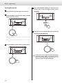
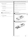
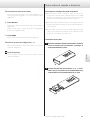
Installing batteries
1 Slide the bottom end of the remote control as
shown in the illustration, and pull out the battery
holder.
2 Insert two AA batteries with ¥ and ^ oriented
as shown in the holder, and put the holder in
again.
Continued on the next page e

16
Remote control parts and functions
When the main unit and the remote control both have buttons
with the same functions, this manual explains how to use one
of the buttons. The other corresponding button can be used in
the same manner.
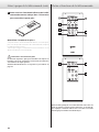
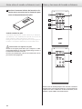
3 Slide the bottom end of the remote control as
shown in the illustration to close the battery
holder.
When to replace batteries
If the distance required between the remote and the main unit
decreases or if the unit stops responding to the remote buttons,
replace both batteries with new ones.
Dispose of the used batteries according to the instructions on them
or requirements set by your local municipality.
V
Precautions concerning batteries
Misuse of batteries could cause them to rupture or leak, which
might result in fire, injury or the staining of nearby materials.
Please read and observe the precautions on page4 carefully.
Notes about the remote control (cont.)

17
English
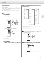
h Mode selection buttons
Press the SACD button to put the remote control into SACD
mode, enabling use of the PLAYER buttons to control the SACD
player/transport.
Press the NET button to put the remote control into NET mode,
enabling use of the PLAYER buttons to control the network
player.
After switching modes, the mode will be retained until the
SACD/NET button is pressed again or the batteries are replaced.
i DIMMER button
Use this to adjust the brightness of the main unit’s display
(page20).
j PLAYER buttons
Use these to control an ESOTERIC player.
oThis remote control can also be used for other ESOTERIC products.
a ON/STANDBY buttons
Use these to turn the unit on or put it into standby mode.
b Input selection buttons
Press these buttons to switch between input sources. Select the
connector that is connected to the device you want to play.
XLR
Press this to cycle through the input connectors that have
their operation mode set to XLR.
ESL-A
Press this to cycle through the input connectors that have
their operation mode set to ESLA.
RCA
Press this to cycle through the RCA connectors.
PHONO
Press this when PHONO input is selected to switch the car-
tridge type (MM/MC).
OPTION
Press this to select input connectors that have been added
using the optional board slot.
oWhen inputting source names, use the ESL-A and XLR but-
tons to select characters.
c Setting adjustment (l/;) buttons
Use these to change setting values when in setting mode.
d MENU button
Press this to enter setting mode (page21).
e OUTPUT button
Press this to switch which connector outputs analog audio
(page20).
Press this when in setting mode to complete changing settings.
f VOLUME (+/−) buttons
Use these to adjust the volume. Press the + button to increase
the volume and the − button to decrease it.
oThe VOLUME (+/−) buttons will not affect input sources set to
THRU> (page26).
g MUTE button
Press this button to temporarily mute the sound. Press this again
to restore the volume setting (page19).
oWhen muted, “MUTE” blinks on the screen.

18
Basic operation
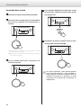
4 Press the OUTPUT button to select the con-
nector type used to output analog audio
(page20).
5 Play the source, and then adjust the volume by
turning the VOLUME knob.
VSudden loud noises might cause hearing damage
and other trouble. Always minimize the volume
before starting playback, and adjust it to an
appropriate level after playback begins.
Turning the unit on
1 Turn on the connected input source devices.
2 Press the INPUT knob until the power indicator
lights to turn the unit on.
oWhen using this unit as a preamp, turn on the power ampli-
fier last.
oThe remote control ON button can also be used to turn on
the unit.
3 Turn the INPUT knob to select an input source.

19
English
Muting the output
Press the MUTE button to temporarily mute the sound. Press it again
to restore the volume setting.
oWhen muted, “MUTE” blinks on the screen.
oYou can also restore the sound by turning the VOLUME knob or by
pressing the VOLUME (+/−) buttons.
oThe VOLUME knob on the unit can also be pressed to mute the
sound.
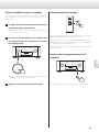
Opening the control cover
Press the open button to open the control cover.
Putting the unit into standby
There might be noise from the speakers if the unit is turned off sud-
denly. Follow the steps below to put the unit into standby.
1 If a connected device is playing back, stop
playback.
oWhen using this unit as a preamp, turn off the power ampli-
fier first.
2 Press the INPUT knob on the unit until “OFF”
appears on the display to activate standby
mode.
oThe remote control STANDBY button can also be used to put
the unit in standby.
3 Turn o the connected input source devices.

20
Basic operation (continued)
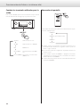
Switching the connectors used for output
Press the OUTPUT button to cycle through which connector type
outputs analog audio.
Speakers
c
SP+PRE
c
PRE
c
Phones (BAL)
c
Phones (UNBAL)
Speaker output only
Speaker output + PREOUT
PREOUT only
Headphones (BAL) only
Headphones (UNBAL) only
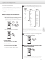
Dimmer
This can be used to adjust the brightness of the main unit’s display.
DIMMER3
c
DIMMER2
c
DIMMER1
c
(off)
(normal brightness)
oEven when the dimmer is off, the display will light at normal
brightness for a few seconds when you press a button or turn a
knob.
oIn setting mode, the display lights at normal brightness.
oEven when set to DIMMER1 or off, setting menus and error mes-
sages will be shown with DIMMER2 brightness.
oPressing and holding the button will set the brightness to
DIMMER2.
La page charge ...
La page charge ...
La page charge ...
La page charge ...
La page charge ...
La page charge ...
La page charge ...
La page charge ...
La page charge ...
La page charge ...
La page charge ...
La page charge ...
La page charge ...
La page charge ...
La page charge ...
La page charge ...
La page charge ...
La page charge ...
La page charge ...
La page charge ...
La page charge ...
La page charge ...
La page charge ...
La page charge ...
La page charge ...
La page charge ...
La page charge ...
La page charge ...
La page charge ...
La page charge ...
La page charge ...
La page charge ...
La page charge ...
La page charge ...
La page charge ...
La page charge ...
La page charge ...
La page charge ...
La page charge ...
La page charge ...
La page charge ...
La page charge ...
La page charge ...
La page charge ...
La page charge ...
La page charge ...
La page charge ...
La page charge ...
La page charge ...
La page charge ...
La page charge ...
La page charge ...
La page charge ...
La page charge ...
La page charge ...
La page charge ...
La page charge ...
La page charge ...
La page charge ...
La page charge ...
La page charge ...
La page charge ...
La page charge ...
La page charge ...
La page charge ...
La page charge ...
La page charge ...
La page charge ...
-
 1
1
-
 2
2
-
 3
3
-
 4
4
-
 5
5
-
 6
6
-
 7
7
-
 8
8
-
 9
9
-
 10
10
-
 11
11
-
 12
12
-
 13
13
-
 14
14
-
 15
15
-
 16
16
-
 17
17
-
 18
18
-
 19
19
-
 20
20
-
 21
21
-
 22
22
-
 23
23
-
 24
24
-
 25
25
-
 26
26
-
 27
27
-
 28
28
-
 29
29
-
 30
30
-
 31
31
-
 32
32
-
 33
33
-
 34
34
-
 35
35
-
 36
36
-
 37
37
-
 38
38
-
 39
39
-
 40
40
-
 41
41
-
 42
42
-
 43
43
-
 44
44
-
 45
45
-
 46
46
-
 47
47
-
 48
48
-
 49
49
-
 50
50
-
 51
51
-
 52
52
-
 53
53
-
 54
54
-
 55
55
-
 56
56
-
 57
57
-
 58
58
-
 59
59
-
 60
60
-
 61
61
-
 62
62
-
 63
63
-
 64
64
-
 65
65
-
 66
66
-
 67
67
-
 68
68
-
 69
69
-
 70
70
-
 71
71
-
 72
72
-
 73
73
-
 74
74
-
 75
75
-
 76
76
-
 77
77
-
 78
78
-
 79
79
-
 80
80
-
 81
81
-
 82
82
-
 83
83
-
 84
84
-
 85
85
-
 86
86
-
 87
87
-
 88
88


Esoteric F-01 Le manuel du propriétaire
- Catégorie
- Équipement musical supplémentaire
- Taper
- Le manuel du propriétaire
- Ce manuel convient également à
dans d''autres langues
- English: Esoteric F-01 Owner's manual
- español: Esoteric F-01 El manual del propietario
Documents connexes
-
Esoteric Grandioso F1 Le manuel du propriétaire
-
Esoteric Grandioso C1X Le manuel du propriétaire
-
-
-
-
-
-