Lifetime 90568 Le manuel du propriétaire
- Taper
- Le manuel du propriétaire

Icon Legend................................2
Notices....................................3
Initial Setup...............................4
Pole Assembly.............................7
Extension Arm Assembly............10
Handle Assembly......................14
Backboard-to-Rim Assembly......17
Parts Identifi er..........................i-iv
Backboard-to-Pole Assembly......24
Final Assembly..........................27
Maintenance Instructions..........32
Registration........................33
Warning Sticker........................34
Warranty................................35
TABLE OF CONTENTSTOOLS REQUIRED
3/4" (x2)
5/16"
(x1, included) Rubber Mallet
Electric Drill
Carpenter’s Level Shovel
(80 lb bag x 13)
Concrete Mix
Tape Measure
1/2" (x2)
3/8"
(x1, included)
9/16" (x2)
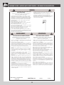
CONTACT LIFETIME CUSTOMER SERVICE:
Call: 1-800-225-3865
7:00 am–5:00 pm (Monday–Friday) MST
and 9:00 am–1:00 pm Saturday MST
QUESTIONS? Model Number: 90568
Product ID:
For Customer Service in Mainland
Europe and the United Kingdom,
E-mail: [email protected]
Live Chat:
www.lifetime.com/customerservice
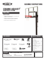
ASSEMBLY INSTRUCTIONS
MODEL 90568
CRANK ADJUST®
BASKETBALL SYSTEM
• Requires at least 1040 lb (472 kg) of concrete mix to fi ll
a volume of 7.78 ft3 (0.22 m3)
• Requires at least 3 days (72 hours) for concrete to
cure, plus 3–4 hours to complete assembly steps
• At least 3 people recommended for setup
BEFORE ASSEMBLY:

2
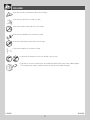
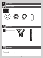
• Indicates the parts to be used for a section.
• Indicates special heed should be taken when reading.
• Indicates the hardware to be used for a section.
• Indicates the tools to be used for a section.
• Indicates no hardware required for a specifi c page.
• Indicates no parts required for a specifi c section.
• Indicates to use/not to use an electric drill for a specifi c step.
ICON LEGEND
• Indicates the use of a centerlock nut. A nut with this marking will require some effort to tighten.
This hardware was designed with this feature in order to prevent loosening later.
1189604 D 10/20/2020

3
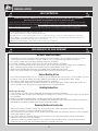
WARNINGS & NOTICES
Most injuries are caused by misuse and/or not following instructions. Use caution when using this product.
To ensure safety, do not attempt to assemble this product without following the instructions carefully. Check entire box and inside all packing
material for parts and/or additional instruction material. Before beginning assembly, read the instructions and identify parts using the hardware
identifi er and parts list in this document. Proper and complete assembly, use and supervision are essential for proper operation and to reduce the
risk of accident or injury. A high probability of serious injury exists if this product is not installed, maintained, and operated properly.
FAILURE TO FOLLOW THESE WARNINGS MAY RESULT IN SERIOUS INJURY OR PROPERTY DAMAGE AND WILL VOID WARRANTY.
Owner must ensure that all players know and follow these rules for safe operation of the system.
• If using a ladder during assembly, use extreme caution.
• Three capable adults are recommended for this operation.
• Assemble the pole sections properly. Failure to do so could cause the pole sections to separate during play or transport.
• Before digging, contact utility company to locate underground power cables, gas, and water lines. Ensure that there are no
overhead power lines within 20' (7 m) radius of pole locations.
• Minimum operational height is 6'-6" (1.98 m) to the bottom of the backboard.
SAFETY INSTRUCTIONS
SAFE HANDLING OF THE GLASS BACKBOARD
BEFORE & DURING ASSEMBLY
1. Thoroughly inspect the backboard before beginning assembly. Do not use the backboard if there are any chips,
cracks, or other defects in the board. Call our customer service department if any problems are found.
2. Use extreme caution when handling or working around the backboard.
3. Keep tools, hardware, and other sharp and heavy objects away from the backboard.
4. Never rest the backboard directly on a hard surface, such as concrete or pavement. Always place cardboard or
other cushioning material between the backboard and the ground or other hard surfaces.
5. Always lay the backboard fl at. Never place it in a position where it might tip over and break.
6. Glass is very heavy. Always use at least two adults when picking up or moving the backboard.
General Handling & Care
1. Inspect the backboard before each use. Do not use the backboard if there are any chips, cracks, or other defects in
the board. If any signs of damage are found, follow the instructions for “handling broken glass” below.
2. Use extreme caution when handling or working around the backboard.
3. The backboard was designed for use with a basketball. Do not use other types of balls or other objects with the
system. Do not use this system for any purpose other than its designed purpose.
Handling Broken Glass
At the fi rst sign of breakage:
1. Keep everyone, especially children, away from the immediate area of the backboard.
2. Put on eye protection, and wear thick utility gloves and long sleeves. Small pieces of tempered glass may pop out of
the backboard.
3. Lower the backboard to its lowest height, and completely cover the backboard with a tarp.
4. Do not remove the backboard from the system without fi rst lowering the system to its lowest setting. Carefully read
and follow the “removing backboard from system” instructions below.
Removing Backboard from System
1. With the backboard at its lowest height, have at least two capable adults support the system while one adult
removes the hardware securing the pole to the playing surface.
2. Have at least three capable adults carefully lay the system down. Make sure to rest the rim on a sheet of cardboard
or other non-abraisive surface.
3. Loosen and remove the hardware from the steps performed in the backboard to pole assembly section of this
manual in reverse order. Keep the hardware.
4. Loosen and remove the hardware from the steps performed inthe backboard to rim assembly section to safely
remove the rim. Keep all parts and hardware from this section for reassembly.

4
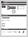
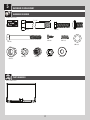
Metal Parts
AOE (x8)
AE0 (x1) CYV (x1)
AEZ (x4)
AKT (x1)
AEI (x4)
Carpenter’s Level Shovel
(80 lb bag x 13)
Concrete Mix
Tape Measure
3/4"
(x2)
Hardware Blister Pack
TOOLS REQUIRED
PARTS REQUIRED
HARDWARE REQUIRED
INITIAL SETUP
1
FNG

5
TOOLS AND HARDWARE REQUIRED
u SECTION 1 (CONTINUED)
AE0 (x1) CYV (x1)
1
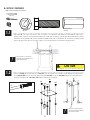
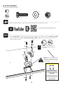
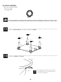
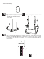
• Dig a hole 30" (76.2 cm) deep and 21" (53 cm) square. The edge of the hole should be flush with the edge of the
playing court. If you live in an area where frost heaves may pose a problem, consult your local building inspector to
determine the appropriate hole depth. Bell out the bottom of the hole as illustrated. We recommend building a form
to keep the top of the concrete level and square. Place the form so it is level with the playing surface.
21"
30"
21"
Before digging, call to locate any buried utility lines.
CAUTION
!
3/4" (x2)
1.1
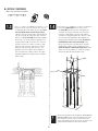
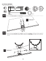
!• There must be a 3' (92 cm) area
behind the pole to allow the user to
adjust the Rim height.
• Thread a nut (AOE) all the way onto each J-bolt (AEI). Slide the threaded ends of the J-bolts through the corner holes
in the template (AKT), and secure them completely with nuts (AOE). Insert the bolt (AEO) through the center hole in the
template and tighten the nut coupler (CYV) onto the bolt as far as it will go.
1.2
AKT
CYV
AOE
AOE
AOE
AOE
AEO
AEI
AOE
!• Ensure the curved ends of the
J-bolts point outward away from
the corners as shown.
AOE (x8)

6
TOOLS AND HARDWARE REQUIRED
u SECTION 1 (CONTINUED)
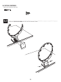
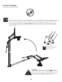
• Center the template (AKT) over the hole. Insert
the J-bolts (AEI) into the concrete and agitate the
Template assembly to eliminate any air bubbles.
Push the J-bolts into the concrete mix until the
Template is resting flat against the concrete. Form
the concrete into a downward slope toward the
playing surface to allow water runoff. The lower four
nuts (AOE) will be in the concrete permanently. Clean
off any concrete on the template or the exposed
portion of the J-bolts. Using a carpenter’s level,
ensure the Template is square to the playing surface. Plate
should be level and about 1/2" above the playing
surface for water to drain off of the steel.
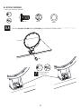
18" (20 cm)
AEZ
80 lb (x13)
• If you are using concrete mix, mix the concrete
according to the instructions on the bags. Please
note that a thicker mix of concrete will dry stronger.
Pour the concrete into the hole, stopping about
18" (46 cm) from the top of the hole. Push the
four pieces of 24" rebar (AEZ) firmly to the bottom
of the hole. The rebar should be arranged in a
square about 8" (20 cm) wide in the center of
the hole so each piece will be next to a J-bolt
when it is placed in the concrete mix. Finish
filling the hole to the top with concrete. The
top of the concrete should extend about 1/2"
(13 mm) above the playing surface and slope
downward toward the playing surface to allow
water runoff.
1.3
AKT
AEI
AOE
Playing surface
!• You are now finished with the initial assembly steps. DO NOT PROCEED
WITH THE ASSEMBLY until the concrete has fully cured. Curing will
take a minimum of 72 hours (3 days). In humid climates or wet
weather, allow additional time for the concrete to cure. Never use the
system without first following the initial setup instructions.
1.4

7
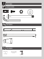
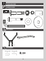
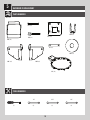
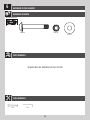
Hardware Blister Pack
HARDWARE REQUIRED
POLE ASSEMBLY
2
CMV (x1)
EJG (x2)
CUB (x2)
BCO
PARTS REQUIRED
ALH (x1)
ALE (x1)
EJS (x2)
Large Parts
TOOLS REQUIRED
9/16" (x1)
5/16"
(x1, included)
EJH (x4)
Electric Drill
ELW (x1)

8
TOOLS AND HARDWARE REQUIRED
u SECTION 2 (CONTINUED)
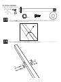
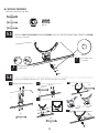
2.1
The gussets and small hole
face the same direction
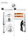
WARNING
The Poles must be seated together! Even if the Poles cover
the slots before seating, they must be struck on a hard
surface three times! Failure to seat the Poles correctly
could allow the Poles to separate during use, which could
lead to serious personal injuries or property damage.
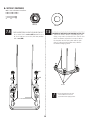
2.2 • Raise the pole assembly about 12 inches off
the ground. Strike the end of the poles against
a piece of scrap wood or thick cardboard three
times to ensure the poles are seated properly.
WARNING
Do not hit your feet with the Pole Sections, as
serious injury could occur.
6x
ALH
ALE 3x
• Slide the flared end of the top pole (ALH) onto
to the swaged end of the bottom pole (ALE). The
small hole in the bottom of the top pole should
face away from the playing surface.
Small
hole

9
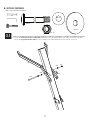
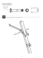
TOOLS AND HARDWARE REQUIRED
u SECTION 2 (CONTINUED)
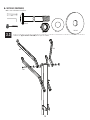
• Attach the pole brackets (EJS) to the top pole (ALH) with the hardware shown.
CMV (x1)
CMV
2.3 • Use the screw (CMV) provided to secure the top pole to the bottom pole. You may need to use a hex driver or
chuck the screw directly into an electric drill.
9/16"
5/16"
EJG (x2)
EJG
ALH
EJG
CUB (x2) EJH (x4)
EJH
EJH
EJH
CUB
EJS
EJS
CUB
EJH
2.4

10
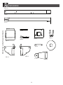
CUG (x2)
AEG (x4)
CYF (x2)
EJM (x2)
EJL (x1)
DIQ (x4)
CZF
Hardware Blister Pack
HARDWARE REQUIRED
EXTENSION ARM ASSEMBLY
3
CUB (x1)
AKE (x1)
Metal Parts
TOOLS REQUIRED
PARTS REQUIRED
AKD (x2)
3/4"
3/8" (included)
9/16"
5/16" (included)
Rubber Mallet
AOQ (x1)

11
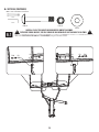
TOOLS AND HARDWARE REQUIRED
u SECTION 3 (CONTINUED)
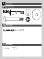
CUG
AEG
AEG CYF
DIQ
DIQ
AKE
3/4"
3/8"
CUG (x1)
AEG (x2)
CYF (x1)
DIQ (x2)
3.1 • Secure the lower extension arm assembly (AKE) through the first set of holes on the pole above the handle brackets.
Ensure the large plastic washers (DIQ) are placed between the extension arms and the pole on each side.

12
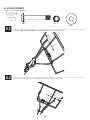
TOOLS AND HARDWARE REQUIRED
u SECTION 3 (CONTINUED)
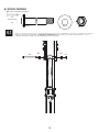
3.2 • Install the hardware indicated in the location shown.
EJL
EJM
EJM CUB
EJM (x2)
EJL (x1) CUB (x1)
9/16"
5/16"

13
TOOLS AND HARDWARE REQUIRED
u SECTION 3 (CONTINUED)
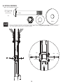
3.3 • Attach the upper extension arms (AKD) to the pole as shown.
CUG (x1)
CUG AEG
AEG CYF
DIQ DIQ
CYF (x1) AEG (x2)
DIQ (x2)
3/4"
3/8"
AKD AKD

14
EJQ (x1)
Hardware Blister Pack
HARDWARE REQUIRED
HANDLE ASSEMBLY
4
CUG (x1)
CYF (x2)
AEG (x4)
DIQ (x2)
BCT
ELX (x1)
PARTS REQUIRED
Large Parts
TOOLS REQUIRED
3/4" 3/8"

15
TOOLS AND HARDWARE REQUIRED
u SECTION 4 (CONTINUED)
AEG AEG CYF
CYF (x1)
3/4"
3/8"
CUG (x1) AEG (x2)
CUG
ELX
• Align the spacer at the top of the crank adjust assembly (ELX) with the holes in the lower extension arms. Secure
using the hardware shown, but do not overtighten this hardware.
4.1

16
TOOLS AND HARDWARE REQUIRED
u SECTION 4 (CONTINUED)
3/4"
3/8"
4.2 • Install the hardware indicated in the location shown. Make sure the large plastic spacers (DIQ) are placed between
the crank adjust assembly and the handle brackets.
CYF (x1)
EJQ (x1)
AEG (x2)
AEG AEG CYF
DIQ DIQ
EJQ
DIQ (x2)

17
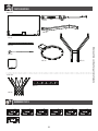
BACKBOARD-TO-RIM ASSEMBLY
5
Hardware Blister Pack
PARTS REQUIRED
HARDWARE REQUIRED
AJI (x1)
Glass and Metal Parts
ANK (x4)
ABK (x4)
ADX (x2) BGZ (x1)
ANL (x1)
5 9/16"
AAX (x1) ABD (x8)
ANM (x2)
ABB (x2) ANN (x2)
ANJ (x2)
ELG (x2)
BCS

18
BACKBOARD-TO-RIM ASSEMBLY
5
TOOLS REQUIRED
Metal Parts
PARTS REQUIRED
AMB (x1)
AMA (x1)
BGY (x1)
AMC (x1)
AMK (x1)
BPZ (x1)
BQA (x1)
1/2" 9/16" 3/4"
(1) (2) (2) (2)
ALX (x1)
ALY (x1)
ANO (x1)

i
This page intentionally left blank
Remove this section for quick reference
PARTS IDENTIFIER

ii
PARTS IDENTIFIER
Remove this section for quick reference
Metal Parts
AMB (x1)
AMA (x1)
BGY (x1)
AMC (x1)
AMK (x1)
BPZ (x1)
BQA (x1)
ALY (x1)
ALH (x1)
ALE (x1)
EJS (x2)
ANO (x1)
La page est en cours de chargement...
La page est en cours de chargement...
La page est en cours de chargement...
La page est en cours de chargement...
La page est en cours de chargement...
La page est en cours de chargement...
La page est en cours de chargement...
La page est en cours de chargement...
La page est en cours de chargement...
La page est en cours de chargement...
La page est en cours de chargement...
La page est en cours de chargement...
La page est en cours de chargement...
La page est en cours de chargement...
La page est en cours de chargement...
La page est en cours de chargement...
La page est en cours de chargement...
La page est en cours de chargement...
La page est en cours de chargement...
La page est en cours de chargement...
-
 1
1
-
 2
2
-
 3
3
-
 4
4
-
 5
5
-
 6
6
-
 7
7
-
 8
8
-
 9
9
-
 10
10
-
 11
11
-
 12
12
-
 13
13
-
 14
14
-
 15
15
-
 16
16
-
 17
17
-
 18
18
-
 19
19
-
 20
20
-
 21
21
-
 22
22
-
 23
23
-
 24
24
-
 25
25
-
 26
26
-
 27
27
-
 28
28
-
 29
29
-
 30
30
-
 31
31
-
 32
32
-
 33
33
-
 34
34
-
 35
35
-
 36
36
-
 37
37
-
 38
38
-
 39
39
-
 40
40


Lifetime 90568 Le manuel du propriétaire
- Taper
- Le manuel du propriétaire
dans d''autres langues
- English: Lifetime 90568 Owner's manual
Documents connexes
-
Lifetime 90734 Le manuel du propriétaire
-
Lifetime 90602 Le manuel du propriétaire
-
-
-
-
-
-
-