
Cappa
Cooker hood
Hotte de cuisine
Dunstabzugshaube
Dampkap
ZHP 637
ZHP 631
MANUALE DI INSTALLAZIONE, USO E MANUTENZIONE
INSTALLATION, USE AND MAINTENANCE HANDBOOK
MANUEL D’INSTRUCTIONS POUR L’INSTALLATION, L’EMPLOI ET L’ENTRETIEN
HANDBUCH FÜR INSTALLATION, BEDIENUNG UND WARTUNG
INSTRUCTIES VOOR MONTAGE, GEBRUIK EN ONDERHOUD

10
GB
Dear Customer,
If you follow the recommendations
contained in this Instruction Manual, your
appliance will give you constant high
performance and will remain efficient for
many years to come.
CONTENTS
RECOMMENDATIONS AND SUGGESTIONS
11
CHARACTERISTICS
12
INSTALLATION
13
USE
15
MAINTENANCE
16

11
GB
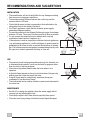
RECOMMENDATIONS AND SUGGESTIONS
INSTALLATION
• The manufacturer will not be held liable for any damages resulting
from incorrect or improper installation.
• The minimum safety distance between the cooker top and the
extractor hood is 650 mm.
• Check that the mains voltage corresponds to that indicated on the
rating plate fixed to the inside of the hood.
• For Class I appliances, check that the domestic power supply
guarantees adequate earthing.
• Connect the extractor to the exhaust flue through a pipe of minimum
diameter 120 mm. The route of the flue must be as short as possible.
• Do not connect the extractor hood to exhaust ducts carrying
combustion fumes (boilers, fireplaces, etc.).
• If the extractor is used in conjunction with non-electrical appliances
(e.g. gas burning appliances), a sufficient degree of aeration must be
guaranteed in the room in order to prevent the backflow of exhaust
gas. The kitchen must have an opening communicating directly with
the open air in order to guarantee the entry of clean air.
USE
• The extractor hood has been designed exclusively for domestic use
to eliminate kitchen smells. Never use the hood for purposes other
than for which it has ben designed.
• Never leave high naked flames under the hood when it is in
operation.
• Adjust the flame intensity to direct it onto the bottom of the pan only,
making sure that it does not engulf the sides.
• Deep fat fryers must be continuously monitored during use:
overheated oil can burst into flames.
• The hood should not be used by children or persons not instructed in
its correct use.
MAINTENANCE
• Switch off or unplug the appliance from the mains supply before
carrying out any maintenance work.
• Clean and/or replace the Filters after the specified time period.
• Clean the hood using a damp cloth and a neutral liquid detergent.
650 mm min.

12
GB
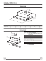
CHARACTERISTICS
Dimensions
Components
Hood Type 45 50 55 60 70 80 90
L
448 498 548 598 698 798 898
Ref. Q.ty Product Components
1 1 Hood Body, complete with: Controls, Light,
Blower, Filters
8 1 Directional Air Outlet grille
20 1 Closing element
Ref. Q.ty Installation Components
12a 4 Screws 4,2 x 44,4
12e 2 Screws 2,9 x 9,5
Q.ty Documentation
1 Instruction Manual
0÷152
280
L
175
ø 120
0÷152
280
L
175
ø 120
12e
8
1
12a
20

13
GB
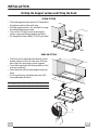
INSTALLATION
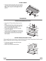
Drilling the Support surface and Fitting the Hood
SCREW FITTING
SNAP-ON FITTING
• The hood support surface must be 135 mm above
the bottom surface of the wall units.
• Drill the support with a ø 4.5 mm drill bit, using
the drilling template provided.
• Cut a hole ø 125 mm in size on the support
surface, using the drilling template provided.
• Fix using the 4 screws 12a (4,2 x 44,4) provided.
• The hood can be installed either directly on the
bottom surface of the wall units (min. 650 mm
above the hob) using snap-on side supports.
• Cut a fitted opening in the bottom surface of the
wall unit, as shown.
• Insert the hood until the side supports snap into
place.
• Lock in position by tightening the screws Vf
from underneath the hood.
Hood Type 45 50 55 60 70 80 90
L1 352 402 452 502 602 702 802
12a
135
125125
15
264
L1
Vf

14
GB
CLOSING ELEMENT
Connections
RECIRCULATION VERSION AIR OUTLET
DUCTED VERSION AIR EXHAUST SYSTEM
When installing the ducted version, connect the hood to the chimney using either a flexible or rigid
pipe ø 120 mm, the choice of which is left to the installer.
• The space between the edge of the hood and the
rear wall can be closed by applying the element
20 provided, using the screws supplied for this
purpose.
• Cut a hole ø 125 mm in the wall unit over the
hood.
• Connect the hood body outlet to the top part of
the wall unit using a rigid or flexible pipe ø120
mm, to be selected by the installer.
• Fix the pipe in position using sufficient pipe
clamps (not supplied).
• Fix the directional grille 8 on the recirculation air
outlet using the 2 screws 12e (2,9 x 9,5) provided.
• Ensure that the activated charcoal filters have
been inserted.
• Fix the pipe in position using sufficient pipe
clamps (not supplied).
• Remove any activated charcoal filters.
20
12e
8
9
125125
ø 120

15
GB
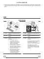
ELECTRICAL CONNECTION
• Connect the hood to the mains through a two-pole switch having a contact gap of at least 3 mm.
• When opening the sliding carriage for the first time after installing the hood, pull it out briskly until it
clicks.
USE
Control panel
L Light Switches the lighting system on
and off
L Light Switches the lighting system on
and off
M Motor Switches the extractor motor on
and off
M Motor Switches the extractor motor on
and off
V Speed Sets the operating speed of the
extractor:
1. Low speed, used for a
continuous and silent air
change in the presence of
light cooking vapour.
2. Medium speed, suitable for
most operating conditions
given the optimum treated air
flow/noise level ratio.
3. Maximum speed, used for
eliminating the highest
cooking vapour emission,
including long periods
V Speed Sets the operating speed of the
extractor:
Low speed, used for a continuous
and silent air change in the
presence of light cooking vapour.
Maximum speed, used for
eliminating the highest cooking
vapour emission, including long
periods
L
M-V
L
M - V
0
1
0
1
2
3

16
GB
MAINTENANCE
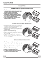
Grease filters
CLEANING METAL SELF-SUPPORTING GREASE FILTERS
CLEANING MULTILAYER METAL GREASE FILTERS
REPLACING SYNTHETIC GREASE FILTER
• The filters must be cleaned every two months of
operation, or more frequently with heavy usage,
and can be washed in a dishwasher.
• Remove the filters one at a time, after
disconnecting the relative fastening elements.
• Wash the filters, taking care not to bend them.
Allow them to dry before refitting.
• When refitting the filters, make sure that the
handle is visible on the outside.
• The filters must be cleaned every two months of
operation, or more frequently with heavy usage,
and can be washed in a dishwasher.
• Release the filter retaining grill using the lateral
sliding handles.
• Remove the filter retaining clips.
• Remove and wash the filters. Allow them to dry
before refitting.
• Replace the filters on the grill, fix them in
position using the filter retaining clips and close
the filter retaining grill.
• The filter is not washable and cannot be
regenerated, and must be replaced approximately
every two months of use, or more frequently with
heavy usage.
• Release the filter holder frame using the lateral
sliding handles.
• Remove the fIlter retaining clips.
• Replace the saturated synthetic filter.
• Fix the new synthetic filter using the retaining
clips and close the filter holder frame.

17
GB
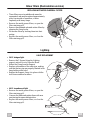
Odour filters (Recirculation version)
REPLACING ACTIVATED CHARCOAL FILTERS
Lighting
LIGHT REPLACEMENT
• These filters are not washable and cannot be
regenerated, and must be replaced approximately
every four months of operation, or more
frequently with heavy usage.
• Remove the metal grease filters, or open the
filter retaining grill.
• Remove the saturated activated carbon filters by
releasing the fixing hooks.
• Fit the new filters by hooking them into their
seating.
• Replace the metal grease filters, or close the
filter retaining grill.
• 20 W halogen light.
• Remove the 2 Screws fixing the Lighting
support, and pull it out of from the Hood.
• Extract the Lamp from the Support.
• Replace with another of the same type, making
sure that the two pins are properly inserted in the
lamp holder socket holes.
• Replace the Support, fixing it in place with the
two Screws removed as above.
• 40 W incandescent light
• Remove the metal grease filters, or open the
filter retaining grill.
• Unscrew the bulbs and replace them with new
ones having the same characteristics.
• Replace the metal grease filters, or close the
filter retaining grill.

Quest’apparecchio é conforme alla norma europea sulla bassa tensione C.E.E. 73/23 relativa
alla sicurezza elettrica e alle norme europee: C.E.E. 89/336 relativa alla compatibilità elettro-
magnetica e C.E.E. 93/68 relativa alla marcatura CE.
This appliance complies with European regulations on low voltages, EEC Directive 73/23 on
electrical safety, and with the following European regulations: EEC Directive 89/336 on
electromagnetic compatibility and EEC Directive 93/68 on EC marking.
Cet équipement est conforme à la norme européenne sur la basse tension C.E.E. 73/23 relati-
ve à la sécurité électrique et aux normes européennes: C.E.E. 89/336 relative à la compatibilité
électromagnétique et C.E.E. 93/68 relative au marquage CE.
Dieses Gerät entspricht den europäischen Niederspannungsrichtlinien 73/23/EWG zur
elektrischen Sicherheit, den europäischen Richtlinien 89/336/EWG zur elektromagnetischen
Verträglichkeit und den Richtlinien 93/68/EWG zur CE-Kennzeichnung
Dit apparaat voldoet aan de Europese Laagspanningsrichtlijn 72/23/EEG inzake de elektrische
veiligheid en aan de Europese normen 89/336/EEG inzake de elektromagnetische compatibiliteit
en 93/68/EEG inzake de CE-markering.
436000562 02 - 020520
-
 1
1
-
 2
2
-
 3
3
-
 4
4
-
 5
5
-
 6
6
-
 7
7
-
 8
8
-
 9
9
-
 10
10


Zanussi ZHP615N Manuel utilisateur
- Catégorie
- Hottes
- Taper
- Manuel utilisateur
dans d''autres langues
- English: Zanussi ZHP615N User manual