3M DBI-SALA® Ultra-Lok™ Self Retracting Lifeline 3503805, 20 ft (6.1m) Rope, 1 ea Mode d'emploi
- Taper
- Mode d'emploi

© 3M 2019
1
Smart Lock SRL SRL-LE
Arc
Flash
ASTM
F887
SRL
LL L W D
x 1
ANSI CSA OSHA
A
LL
D
L
W
B
LL
W
L
D
A
3503800
√
9501479 + 9502194
30 ft
(9 m)
23.5 in
(59.69cm)
9 in
(22.86cm)
4 in
(10.16cm)
310 lb
(140 kg)
310 lb
(140 kg)
420 lb
(191 kg)
A
3503801
√
9501613 + 2100044
30 ft
(9 m)
23.5 in
(59.69cm)
9 in
(22.86cm)
4 in
(10.16cm)
310 lb
(140 kg)
310 lb
(140 kg)
420 lb
(191 kg)
A
3503803
√
9501479 + 9502194
20 ft
(6 m)
23.5 in
(59.69cm)
9 in
(22.86cm)
4 in
(10.16cm)
310 lb
(140 kg)
310 lb
(140 kg)
420 lb
(191 kg)
A
3503804
√
9501613 + 2100044
20 ft
(6 m)
23.5 in
(59.69cm)
9 in
(22.86cm)
4 in
(10.16cm)
310 lb
(140 kg)
310 lb
(140 kg)
420 lb
(191 kg)
A
3503820
√
3500076 + 9502194
35 ft
(10.7 m)
25 in
(63.5cm)
10 in
(25.4cm)
4.3 in
(10.92cm)
310 lb
(140 kg)
310 lb
(140 kg)
420 lb
(191 kg)
A
3503821
√
9501613 + 2100044
35 ft
(10.7 m)
25 in
(63.5cm)
10 in
(25.4cm)
4.3 in
(10.92cm)
310 lb
(140 kg)
310 lb
(140 kg)
420 lb
(191 kg)
A
3503823
√
9501613 + 2100044
50 ft
(15 m)
25 in
(63.5cm)
10 in
(25.4cm)
4.3 in
(10.92cm)
310 lb
(140 kg)
310 lb
(140 kg)
420 lb
(191 kg)
A
3503824
√
9501479 + 9502194
50 ft
(15 m)
25 in
(63.5cm)
10 in
(25.4cm)
4.3 in
(10.92cm)
310 lb
(140 kg)
310 lb
(140 kg)
420 lb
(191 kg)
B
3503802
√
9501087 + 1246446
20 ft
(6 m)
31.5 in
(80.01cm)
9 in
(22.86cm)
4 in
(10.16cm)
310 lb
(140 kg)
310 lb
(140 kg)
310 lb
(140 kg)
B
3503822
√
9501087 + 1246446
30 ft
(9 m)
32.5 in
(82.55cm)
10 in
(25.4cm)
4.3 in
(10.92cm)
310 lb
(140 kg)
310 lb
(140 kg)
310 lb
(140 kg)
C
3503848
√
9501087 + 1246446 +
9501441 + 9506214
30 ft
(9 m)
32.5 in
(82.55cm)
10 in
(25.4cm)
4.3 in
(10.92cm)
310 lb
(140 kg)
N/A
310 lb
(140 kg)
D
1246500 1246446
1.3 ft
(0.4 m)
N/A N/A N/A N/A N/A N/A
A
3503805
√ √
3500075 + 9502194
20 ft
(6 m)
23.5 in
(59.69cm)
9 in
(22.86cm)
4 in
(10.16cm)
310 lb
(140 kg)
310 lb
(140 kg)
420 lb
(191 kg)
C D
LL
INSTRUCTION MANUAL
ANSI Z359.14 Class B OSHA
CSA Z259.2.2-17 Class SRL CSA Z259.2.2-17 Class SRL-LE
FORM NO: 5908284 REV:E
Smart Lock
SELF-RETRACTINg DEvICES

2
2
A
C
D
B
A
F
E
B
C
D
B
A
F
G
E
C
H
I
3
A B
FC
C
4C
FC

3
4
A
C
B
SRL:
130 - 310 lbs
(59 - 140 kg)
B
<4 ft
(1.2m)
4 ft
(1.2m)
5 ft
(1.5m)
6 ft
(1.8m)
7 ft
(2.1m)
8 ft
(2.4m)
9 ft
(2.7m)
>10 ft
(3m)
A
8 ft
(2.4m)
0 ft
(0m)
2.5 ft
(0.76m)
3.7 ft
(1.13m)
4.9 ft
(1.49m)
6 ft
(1.83m)
7 ft
(2.13m)
8 ft
(2.44m)
10 ft
(3m)
0 ft
(0m)
3.1 ft
(0.94m)
4.6 ft
(1.4m)
5.9 ft
(1.8m)
7.1 ft
(2.16m)
8.2 ft
(2.5m)
9.3 ft
(2.83m)
20 ft
(6.1m)
0 ft
(0m)
5.4 ft
(1.65m)
7.7 ft
(2.35m)
9.6 ft
(2.93m)
11.3 ft
(3.44m)
12.8 ft
(3.9m)
14.2 ft
(4.33m)
30 ft
(9.1m)
0 ft
(0m)
7 ft
(2.13m)
10 ft
(3.05m)
12.3 ft
(3.75m)
14.4 ft
(4.39m)
16.2 ft
(4.94m)
17.9 ft
(5.46m)
50
(15.2)
0 ft
(0m)
9.4 ft
(2.87m)
13.4 ft
(4.08m)
16.5 ft
(5.03m)
19.1 ft
(5.82m)
21.5 ft
(6.55m)
23.7 ft
(7.22m)
70 ft
(21.3m)
0 ft
(0m)
11.3 ft
(3.44m)
16.1 ft
(4.91m)
19.8 ft
(6.04m)
22.9 ft
(6.98m)
25.7 ft
(7.83m)
28.3 ft
(8.63m)
C
SRL:
311 - 420 lbs (140 - 191 kg)
SRL-LE:
130 - 310 lbs (59 - 140 kg)
B
<6 ft
(1.8m)
6 ft
(1.8m)
7 ft
(2.1m)
8 ft
(2.4m)
9 ft
(2.7m)
>10 ft
(3m)
A
8 ft
(2.4m)
0 ft (0m) 2.5 ft
(0.76m)
3.8 ft
(1.16m)
4.9 ft
(1.49m)
6 ft
(1.83m)
10 ft
(3m)
0 ft (0m)
3.1 ft
(0.94m)
4.6 ft
(1.4m)
5.9 ft
(1.8m)
7 ft
(2.13m)
20 ft
(6.1m)
0 ft (0m)
5.3 ft
(1.62m)
7.6 ft
(2.32m)
9.5 ft
(2.9m)
11.2 ft
(3.41m)
30 ft
(9.1m)
0 ft (0m)
6.9 ft
(2.1m)
9.9 ft
(3.02m)
12.2 ft
(3.72m)
14.3 ft
(4.36m)
50
(15.2)
0 ft (0m)
9.3 ft
(2.83m)
13.3 ft
(4.05m)
16.4 ft
(5m)
19 ft
(5.79m)
70 ft
(21.3m)
0 ft (0m)
11.3 ft
(3.44m)
16 ft
(4.88m)
19.7 ft
(6m)
22.8 ft
(6.95m)
C
5 6
A B C
A. B. C. D.
E. F. G.
7
≥90°
þ OK
ý NO
<90°

4
8
C
B
A
A
B
C
SRL-LE:
130 - 310 lbs
(59 - 140 kg)
B
0 ft
(0.00m)
2 ft
(0.61m)
5 ft
(1.52m)
10 ft
(3.05m)
15 ft
(4.57m)
20 ft
(6.1m)
25 ft
(7.62m)
>25 ft
(>7.62m)
A
2 ft
(0.61m)
15 ft
(4.57m)
15.8 ft
(4.82m)
5 ft
(1.52m)
15 ft
(4.57m)
15.4 ft
(4.69m)
17.1 ft
(5.21m)
10 ft
(3.05m)
15 ft
(4.57m)
15.2 ft
(4.63m)
16.2 ft
(4.94m)
19.1 ft
(5.82m)
15 ft
(4.57m)
15 ft
(4.57m)
15.1 ft
(4.6m)
15.8 ft
(4.82m)
18 ft
(5.49m)
21.2 ft
(6.46m)
20 ft
(6.1m)
15 ft
(4.57m)
15.1 ft
(4.6m)
15.6 ft
(4.75m)
17.4 ft
(5.3m)
20 ft
(6.1m)
23.3 ft
(7.1m)
25 ft
(7.62m)
15 ft
(4.57m)
15.1 ft
(4.6m)
15.5 ft
(4.72m)
16.9 ft
(5.15m)
19.2 ft
(5.85m)
22 ft
(6.71m)
25.4 ft
(7.74m)
30 ft
(9.14m)
15 ft
(4.57m)
15.1 ft
(4.6m)
15.4 ft
(4.69m)
16.6 ft
(5.06m)
18.5 ft
(5.64m)
21.1 ft
(6.43m)
24.1 ft
(7.35m)
35 ft
(10.67m)
15 ft
(4.57m)
15.1 ft
(4.6m)
15.4 ft
(4.69m)
16.4 ft
(5m)
18.1 ft
(5.52m)
20.3 ft
(6.19m)
23 ft
(7.01m)
40 ft
(12.19m)
15 ft
(4.57m)
15 ft
(4.57m)
15.3 ft
(4.66m)
16.2 ft
(4.94m)
17.7 ft
(5.39m)
19.7 ft
(6m)
22.2 ft
(6.77m)
50 ft
(15.24m)
15 ft
(4.57m)
15 ft
(4.57m)
15.2 ft
(4.63m)
16 ft
(4.88m)
17.2 ft
(5.24m)
18.9 ft
(5.76m)
20.9 ft
(6.37m)
55 ft
(16.76m)
15 ft
(4.57m)
15 ft
(4.57m)
15.2 ft
(4.63m)
15.9 ft
(4.85m)
17 ft
(5.18m)
18.5 ft
(5.64m)
20.4 ft
(6.22m)
C

5
9 10
A
B
A
C
B
D
A
B
A
B
11
1
2
C
C
3
û
12 13 14
A
B
C
A
C
B
ü
û
A
ü

6
15 16 17
A
B
C
D
E
G
F
H
A
B
C
D
E
F
G
H
I
J
B
C
A
D
E
18
SRL
A
F
G
C
E
D
B
N
SRL-LE
A
I
C
J
H
B
D
SRL-LE
3503848
K
ML
A
C
B
D
J
A
B
1
B

7
18
C
1
D
E
4
G
PATENTS PENDING
RESERVE LIFELINE / CORDE D’ASSURANCE DE RÉSERVE:
JOURNAL D’INSPECTION
INITIAL
INSPECTION LOG /
INITIALES INITIALES
DATE
INITIAL
DATE
ISO17025 accredited
verification to ANSI Z359.7
Sound indicator helps inform users of a properly
functioning locking mechanism.
INSPECTION NOTE / REMARQUE POUR L’INSPECTION:
This product is RFID enabled and contains an electronic tag that can be read by compatible readers - providing inspection logs,
inventory management and other safety information. Ce produit est validé dans RFID et contient une étiquette électronique lisible
par des lecteurs compatibles fournissant des journaux d’inspection, la gestion des stocks et d’autres renseignements sur la sécurité.
Inspect for deployment of reserve lifeline by fully extending line. If reserve ferrule (ring fixed to lifeline) or warning label is visible near housing end of line, remove unit from use for repair.
Inspectez le déploiement de la corde d’assurance de réserve en étirant complètement la corde. Si une bague (bague fixée sur la corde d’assurance) de réserve ou une étiquette
d’avertissement est visible près de l’extrémité du boîtier de la corde, retirez l’unité du service pour la réparation.
3M.com/FallProtection
9513637 Rev. F
WARNING/
AVERTISSEMENT
Read instructions before use. Manufacturer's instructions supplied with this product must be followed for proper use.
Failure to follow instructions may result in serious injury or death. This device shall be removed from service when the impact indicator is deployed. Lire les instructions
avant utilisation. Il faut suivre les instructions du fabricant fournies avec ce produit avant toute utilisation. Le non-respect de ces instructions pourrait entraîner de graves
blessures ou la mort. Ce dispositif sera enlevé du service quand l’indicateur d’impact sera déployé.
USE/UTILISATION:
Next Service
Prochain entretien
DO NOT REMOVE THIS LABEL
Max arresting force
Force d’arrêt maximale
Max arresting distance
Distance d’arrêt maximale
INSPECTION:
Before each use, and at least monthly, inspect in accordance with the User Manual including locking function (pull sharply to test),
retraction, lifeline condition, function and condition of connector, housing and fasteners, legibility of labels, and any evidence of defects, damage or missing
parts. Inspection by a competent person required at least annually. In Canada this device shall be returned to the manufacturer or approved service agent no
more than 2 years after the date of manufacture for inspection and maintenance, and annually thereafter. See User Manual. Do not use if inspection reveals
an unsafe condition. Not user repairable. Avant chaque utilisation et au moins une fois par mois, procédez à l’inspection conformément au manuel de
l’utilisateur incluant la fonction de verrouillage (tirez fermement pour la tester), le mécanisme de rétraction, l’état de la corde d'assurance, le fonctionnement et
l’état du connecteur, du boîtier et des dispositifs de fixation et la lisibilité des étiquettes. Assurez-vous en outre qu’il n’y ait aucun défaut ou dommage et aucune
pièce manquante. Une inspection par une personne qualifiée doit être réalisée au moins une fois par an. Au Canada, ce dispositif doit être retourné au fabricant
ou à un agent de service agréé pour inspection et entretien au plus tard deux ans suivant la date de fabrication, et chaque année par la suite. Reportez-vous au
manuel de l’utilisateur. Si une inspection révèle un état non sécuritaire, n’utilisez pas cet équipement. N’est pas réparable par l’utilisateur.
Capacity/Capacité
Avg. arresting force
Force d’arrêt moyenne
NE PAS RETIRER CETTE ÉTIQUETTE
Exposed color band on hook indicates impact loading and must be
removed from service.
La bande de couleur visible sur le crochet indique une charge d’impact
et le dispositif doit être retiré du service.
BREVETS EN INSTANCE
L’indicateur sonore aide à informer les utilisateurs
que le mécanisme de verrouillage fonctionne
correctement.
ANSI / OSHA CSA OSHA
130-310 lbs (59-140 Kg)
1,350 lbs (6.0 kN)
900 lbs (4.0 kN) 900 Ibs. (4.0kN)
30 in. (0.8 m) 47 in. (1.2 m)
1,350 lbs (6.0 kN)
N/A
311-420 lbs (141-191 Kg)
1,800 lbs (8.0 kN)
42 in. (1.1 m)
Mfrd. (yr, mo):
Fabr. (an, mo):
Lot:
Model No.:
N° de modèle :
Material:
Matériau:
Length (m ,ft):
Longueur (m, pi):
Serial No:
N° de série:
SRD (SRL)
X 1
130-311 lbs (59-141 Kg)
WARNING / AVERTISSEMENT
- Avoid lifeline contact with sharp and abrasive surfaces.
- Évitez que la corde d’assurance entre en contact avec des surfaces coupantes ou abrasives.
- Free fall limit = 0’
- Limite de chute libre = 0 pi
- For Vertical use only.
- Pour utilisation à la verticale seulement.
- Do not work above anchorage level.
-
Ne travaillez pas au-dessus du niveau d’ancrage.
Code
Lifeline Base Material Properties
(G)
(S)
(L)
(V)
Galvanized Steel
Stainless Steel
Galvanized Steel
Vectran Rope
7x19
7x19
7x19
12 Strand
5mm (3/16”)
5mm (3/16”)
5.5mm (7/32”)
6mm (1/4”)
Material Construction Size
(K) Technora/Kevlar Rope
Double Braid
5.5mm (7/32”)
(T) Technora/Kevlar Rope
24 strand Double Braid
5.5mm (7/32”)
Code
Propriétés du matériau de base de la corde d’assurance
(G)
(S)
(L)
(V)
Acier galvanisé
Acier inoxydable
Acier galvanisé
Corde Vectran
7x19
7x19
7x19
12 brins
5mm (3/16”)
5mm (3/16”)
5.5mm (7/32”)
6mm (1/4”)
Matériel Taille
Secteur de la construction
(K)
Corde Technora/Kevlar Double tresse
5.5mm (7/32”)
(T)
Corde Technora/Polyester
Double tresse 24 brins
5.5mm (7/32”)
Anchorage strength requirement 22 kN (5000 lb). Anchor unit as directly
above work area as possible to reduce swing fall hazard.
Full body
harness
required for use with this device. For use by trained persons only. This unit is suitable for use with horizontal lifelines. See user manual for additional information
including suitability for horizontal use.
Contact 3M with any questions about the proper use of this product. Normes de résistance d’ancrage 22 kN (5000 lb). Ancrez l’unité le
plus précisément possible au-dessus de la zone de travail pour réduire le risque de chute oscillante. Un harnais de sécurité complet est nécessaire pour utiliser ce dispositif.
Pour une utilisation par des personnes formées uniquement. Cette unité est conçue pour être utilisée avec des cordes d'assurance horizontales. Pour en savoir plus, y compris
sur l’efficacité d’une utilisation horizontale, référez-vous au manuel d’utilisateur. Communiquez avec 3M pour toute question sur la bonne utilisation de ce produit.
F
9514986 Rev. A
N
SRL

8
18
H
5
J
PATENTS PENDING
RESERVE LIFELINE / CORDE D’ASSURANCE DE RÉSERVE:
ISO17025 accredited
verification to ANSI Z359.7
Sound indicator helps inform users of a properly
functioning locking mechanism.
INSPECTION NOTE / REMARQUE POUR L’INSPECTION:
This product is RFID enabled and contains an electronic tag that can be read by compatible readers - providing inspection logs,
inventory management and other safety information. Ce produit est validé dans RFID et contient une étiquette électronique lisible
par des lecteurs compatibles fournissant des journaux d’inspection, la gestion des stocks et d’autres renseignements sur la sécurité.
Inspect for deployment of reserve lifeline by fully extending line. If reserve ferrule (ring fixed to lifeline) or warning label is visible near housing end of line, remove unit from use for repair.
Inspectez le déploiement de la corde d’assurance de réserve en étirant complètement la corde. Si une bague (bague fixée sur la corde d’assurance) de réserve ou une étiquette
d’avertissement est visible près de l’extrémité du boîtier de la corde, retirez l’unité du service pour la réparation.
INSPECTION:
Before each use, and at least monthly, inspect in accordance with the User Manual including locking function (pull sharply to test),
retraction, lifeline condition, function and condition of connector, housing and fasteners, legibility of labels, and any evidence of defects, damage or missing
parts. Inspection by a competent person required at least annually. In Canada this device shall be returned to the manufacturer or approved service agent no
more than 2 years after the date of manufacture for inspection and maintenance, and annually thereafter. See User Manual. Do not use if inspection reveals
an unsafe condition. Not user repairable. Avant chaque utilisation et au moins une fois par mois, procédez à l’inspection conformément au manuel de
l’utilisateur incluant la fonction de verrouillage (tirez fermement pour la tester), le mécanisme de rétraction, l’état de la corde d'assurance, le fonctionnement et
l’état du connecteur, du boîtier et des dispositifs de fixation et la lisibilité des étiquettes. Assurez-vous en outre qu’il n’y ait aucun défaut ou dommage et aucune
pièce manquante. Une inspection par une personne qualifiée doit être réalisée au moins une fois par an. Au Canada, ce dispositif doit être retourné au fabricant
ou à un agent de service agréé pour inspection et entretien au plus tard deux ans suivant la date de fabrication, et chaque année par la suite. Reportez-vous au
manuel de l’utilisateur. Si une inspection révèle un état non sécuritaire, n’utilisez pas cet équipement. N’est pas réparable par l’utilisateur.
Exposed color band on hook indicates impact loading and must be
removed from service.
La bande de couleur visible sur le crochet indique une charge d’impact
et le dispositif doit être retiré du service.
BREVETS EN INSTANCE
L’indicateur sonore aide à informer les utilisateurs
que le mécanisme de verrouillage fonctionne
correctement.
X 1
3
2
PATENTS PENDING
RESERVE LIFELINE / CORDE D’ASSURANCE DE RÉSERVE:
JOURNAL D’INSPECTION
INITIAL
INSPECTION LOG /
INITIALES INITIALES
DATE
INITIAL
DATE
ISO17025 accredited
verification to ANSI Z359.7
Sound indicator helps inform users of a properly
functioning locking mechanism.
INSPECTION NOTE / REMARQUE POUR L’INSPECTION:
This product is RFID enabled and contains an electronic tag that can be read by compatible readers - providing inspection logs,
inventory management and other safety information. Ce produit est validé dans RFID et contient une étiquette électronique lisible
par des lecteurs compatibles fournissant des journaux d’inspection, la gestion des stocks et d’autres renseignements sur la sécurité.
Inspect for deployment of reserve lifeline by fully extending line. If reserve ferrule (ring fixed to lifeline) or warning label is visible near housing end of line, remove unit from use for repair.
Inspectez le déploiement de la corde d’assurance de réserve en étirant complètement la corde. Si une bague (bague fixée sur la corde d’assurance) de réserve ou une étiquette
d’avertissement est visible près de l’extrémité du boîtier de la corde, retirez l’unité du service pour la réparation.
3M.com/FallProtection
9513637 Rev. F
WARNING/
AVERTISSEMENT
Read instructions before use. Manufacturer's instructions supplied with this product must be followed for proper use.
Failure to follow instructions may result in serious injury or death. This device shall be removed from service when the impact indicator is deployed. Lire les instructions
avant utilisation. Il faut suivre les instructions du fabricant fournies avec ce produit avant toute utilisation. Le non-respect de ces instructions pourrait entraîner de graves
blessures ou la mort. Ce dispositif sera enlevé du service quand l’indicateur d’impact sera déployé.
USE/UTILISATION:
Next Service
Prochain entretien
DO NOT REMOVE THIS LABEL
Max arresting force
Force d’arrêt maximale
Max arresting distance
Distance d’arrêt maximale
INSPECTION:
Before each use, and at least monthly, inspect in accordance with the User Manual including locking function (pull sharply to test),
retraction, lifeline condition, function and condition of connector, housing and fasteners, legibility of labels, and any evidence of defects, damage or missing
parts. Inspection by a competent person required at least annually. In Canada this device shall be returned to the manufacturer or approved service agent no
more than 2 years after the date of manufacture for inspection and maintenance, and annually thereafter. See User Manual. Do not use if inspection reveals
an unsafe condition. Not user repairable. Avant chaque utilisation et au moins une fois par mois, procédez à l’inspection conformément au manuel de
l’utilisateur incluant la fonction de verrouillage (tirez fermement pour la tester), le mécanisme de rétraction, l’état de la corde d'assurance, le fonctionnement et
l’état du connecteur, du boîtier et des dispositifs de fixation et la lisibilité des étiquettes. Assurez-vous en outre qu’il n’y ait aucun défaut ou dommage et aucune
pièce manquante. Une inspection par une personne qualifiée doit être réalisée au moins une fois par an. Au Canada, ce dispositif doit être retourné au fabricant
ou à un agent de service agréé pour inspection et entretien au plus tard deux ans suivant la date de fabrication, et chaque année par la suite. Reportez-vous au
manuel de l’utilisateur. Si une inspection révèle un état non sécuritaire, n’utilisez pas cet équipement. N’est pas réparable par l’utilisateur.
Capacity/Capacité
Avg. arresting force
Force d’arrêt moyenne
NE PAS RETIRER CETTE ÉTIQUETTE
Exposed color band on hook indicates impact loading and must be
removed from service.
La bande de couleur visible sur le crochet indique une charge d’impact
et le dispositif doit être retiré du service.
BREVETS EN INSTANCE
L’indicateur sonore aide à informer les utilisateurs
que le mécanisme de verrouillage fonctionne
correctement.
ANSI / OSHA CSA OSHA
130-310 lbs (59-140 Kg)
1,350 lbs (6.0 kN)
900 lbs (4.0 kN) 900 Ibs. (4.0kN)
30 in. (0.8 m) 47 in. (1.2 m)
1,350 lbs (6.0 kN)
N/A
311-420 lbs (141-191 Kg)
1,800 lbs (8.0 kN)
42 in. (1.1 m)
Mfrd. (yr, mo):
Fabr. (an, mo):
Lot:
Model No.:
N° de modèle :
Material:
Matériau:
Length (m ,ft):
Longueur (m, pi):
Serial No:
N° de série:
SRD (SRL)
X 1
130-311 lbs (59-141 Kg)
WARNING / AVERTISSEMENT
- Avoid lifeline contact with sharp and abrasive surfaces.
- Évitez que la corde d’assurance entre en contact avec des surfaces coupantes ou abrasives.
- Free fall limit = 0’
- Limite de chute libre = 0 pi
- For Vertical use only.
- Pour utilisation à la verticale seulement.
- Do not work above anchorage level.
-
Ne travaillez pas au-dessus du niveau d’ancrage.
Code
Lifeline Base Material Properties
(G)
(S)
(L)
(V)
Galvanized Steel
Stainless Steel
Galvanized Steel
Vectran Rope
7x19
7x19
7x19
12 Strand
5mm (3/16”)
5mm (3/16”)
5.5mm (7/32”)
6mm (1/4”)
Material Construction Size
(K) Technora/Kevlar Rope
Double Braid
5.5mm (7/32”)
(T) Technora/Kevlar Rope
24 strand Double Braid
5.5mm (7/32”)
Code
Propriétés du matériau de base de la corde d’assurance
(G)
(S)
(L)
(V)
Acier galvanisé
Acier inoxydable
Acier galvanisé
Corde Vectran
7x19
7x19
7x19
12 brins
5mm (3/16”)
5mm (3/16”)
5.5mm (7/32”)
6mm (1/4”)
Matériel Taille
Secteur de la construction
(K)
Corde Technora/Kevlar Double tresse
5.5mm (7/32”)
(T)
Corde Technora/Polyester
Double tresse 24 brins
5.5mm (7/32”)
Anchorage strength requirement 22 kN (5000 lb). Anchor unit as directly
above work area as possible to reduce swing fall hazard.
Full body
harness
required for use with this device. For use by trained persons only. This unit is suitable for use with horizontal lifelines. See user manual for additional information
including suitability for horizontal use.
Contact 3M with any questions about the proper use of this product. Normes de résistance d’ancrage 22 kN (5000 lb). Ancrez l’unité le
plus précisément possible au-dessus de la zone de travail pour réduire le risque de chute oscillante. Un harnais de sécurité complet est nécessaire pour utiliser ce dispositif.
Pour une utilisation par des personnes formées uniquement. Cette unité est conçue pour être utilisée avec des cordes d'assurance horizontales. Pour en savoir plus, y compris
sur l’efficacité d’une utilisation horizontale, référez-vous au manuel d’utilisateur. Communiquez avec 3M pour toute question sur la bonne utilisation de ce produit.
I
L
K
PATENTS PENDING
RESERVE LIFELINE / CORDE D’ASSURANCE DE RÉSERVE:
ISO17025 accredited
verification to ANSI Z359.7
Sound indicator helps inform users of a properly
functioning locking mechanism.
INSPECTION NOTE / REMARQUE POUR L’INSPECTION:
This product is RFID enabled and contains an electronic tag that can be read by compatible readers - providing inspection logs,
inventory management and other safety information. Ce produit est validé dans RFID et contient une étiquette électronique lisible
par des lecteurs compatibles fournissant des journaux d’inspection, la gestion des stocks et d’autres renseignements sur la sécurité.
Inspect for deployment of reserve lifeline by fully extending line. If reserve ferrule (ring fixed to lifeline) or warning label is visible near housing end of line, remove unit from use for repair.
Inspectez le déploiement de la corde d’assurance de réserve en étirant complètement la corde. Si une bague (bague fixée sur la corde d’assurance) de réserve ou une étiquette
d’avertissement est visible près de l’extrémité du boîtier de la corde, retirez l’unité du service pour la réparation.
INSPECTION:
Before each use, and at least monthly, inspect in accordance with the User Manual including locking function (pull sharply to test),
retraction, lifeline condition, function and condition of connector, housing and fasteners, legibility of labels, and any evidence of defects, damage or missing
parts. Inspection by a competent person required at least annually. In Canada this device shall be returned to the manufacturer or approved service agent no
more than 2 years after the date of manufacture for inspection and maintenance, and annually thereafter. See User Manual. Do not use if inspection reveals
an unsafe condition. Not user repairable. Avant chaque utilisation et au moins une fois par mois, procédez à l’inspection conformément au manuel de
l’utilisateur incluant la fonction de verrouillage (tirez fermement pour la tester), le mécanisme de rétraction, l’état de la corde d'assurance, le fonctionnement et
l’état du connecteur, du boîtier et des dispositifs de fixation et la lisibilité des étiquettes. Assurez-vous en outre qu’il n’y ait aucun défaut ou dommage et aucune
pièce manquante. Une inspection par une personne qualifiée doit être réalisée au moins une fois par an. Au Canada, ce dispositif doit être retourné au fabricant
ou à un agent de service agréé pour inspection et entretien au plus tard deux ans suivant la date de fabrication, et chaque année par la suite. Reportez-vous au
manuel de l’utilisateur. Si une inspection révèle un état non sécuritaire, n’utilisez pas cet équipement. N’est pas réparable par l’utilisateur.
Exposed color band on hook indicates impact loading and must be
removed from service.
La bande de couleur visible sur le crochet indique une charge d’impact
et le dispositif doit être retiré du service.
BREVETS EN INSTANCE
L’indicateur sonore aide à informer les utilisateurs
que le mécanisme de verrouillage fonctionne
correctement.
X 1
J
PATENTS PENDING
RESERVE LIFELINE / CORDE D’ASSURANCE DE RÉSERVE:
JOURNAL D’INSPECTION
INITIAL
INSPECTION LOG /
INITIALES INITIALES
DATE
INITIAL
DATE
ISO17025 accredited
verification to ANSI Z359.7
Sound indicator helps inform users of a properly
functioning locking mechanism.
INSPECTION NOTE / REMARQUE POUR L’INSPECTION:
This product is RFID enabled and contains an electronic tag that can be read by compatible readers - providing inspection logs,
inventory management and other safety information. Ce produit est validé dans RFID et contient une étiquette électronique lisible
par des lecteurs compatibles fournissant des journaux d’inspection, la gestion des stocks et d’autres renseignements sur la sécurité.
Inspect for deployment of reserve lifeline by fully extending line. If reserve ferrule (ring fixed to lifeline) or warning label is visible near housing end of line, remove unit from use for repair.
Inspectez le déploiement de la corde d’assurance de réserve en étirant complètement la corde. Si une bague (bague fixée sur la corde d’assurance) de réserve ou une étiquette
d’avertissement est visible près de l’extrémité du boîtier de la corde, retirez l’unité du service pour la réparation.
3M.com/FallProtection
9513637 Rev. F
WARNING/
AVERTISSEMENT
Read instructions before use. Manufacturer's instructions supplied with this product must be followed for proper use.
Failure to follow instructions may result in serious injury or death. This device shall be removed from service when the impact indicator is deployed. Lire les instructions
avant utilisation. Il faut suivre les instructions du fabricant fournies avec ce produit avant toute utilisation. Le non-respect de ces instructions pourrait entraîner de graves
blessures ou la mort. Ce dispositif sera enlevé du service quand l’indicateur d’impact sera déployé.
USE/UTILISATION:
Next Service
Prochain entretien
DO NOT REMOVE THIS LABEL
Max arresting force
Force d’arrêt maximale
Max arresting distance
Distance d’arrêt maximale
INSPECTION:
Before each use, and at least monthly, inspect in accordance with the User Manual including locking function (pull sharply to test),
retraction, lifeline condition, function and condition of connector, housing and fasteners, legibility of labels, and any evidence of defects, damage or missing
parts. Inspection by a competent person required at least annually. In Canada this device shall be returned to the manufacturer or approved service agent no
more than 2 years after the date of manufacture for inspection and maintenance, and annually thereafter. See User Manual. Do not use if inspection reveals
an unsafe condition. Not user repairable. Avant chaque utilisation et au moins une fois par mois, procédez à l’inspection conformément au manuel de
l’utilisateur incluant la fonction de verrouillage (tirez fermement pour la tester), le mécanisme de rétraction, l’état de la corde d'assurance, le fonctionnement et
l’état du connecteur, du boîtier et des dispositifs de fixation et la lisibilité des étiquettes. Assurez-vous en outre qu’il n’y ait aucun défaut ou dommage et aucune
pièce manquante. Une inspection par une personne qualifiée doit être réalisée au moins une fois par an. Au Canada, ce dispositif doit être retourné au fabricant
ou à un agent de service agréé pour inspection et entretien au plus tard deux ans suivant la date de fabrication, et chaque année par la suite. Reportez-vous au
manuel de l’utilisateur. Si une inspection révèle un état non sécuritaire, n’utilisez pas cet équipement. N’est pas réparable par l’utilisateur.
Capacity/Capacité
Avg. arresting force
Force d’arrêt moyenne
NE PAS RETIRER CETTE ÉTIQUETTE
Exposed color band on hook indicates impact loading and must be
removed from service.
La bande de couleur visible sur le crochet indique une charge d’impact
et le dispositif doit être retiré du service.
BREVETS EN INSTANCE
L’indicateur sonore aide à informer les utilisateurs
que le mécanisme de verrouillage fonctionne
correctement.
ANSI / OSHA CSA OSHA
130-310 lbs (59-140 Kg)
1,350 lbs (6.0 kN)
900 lbs (4.0 kN) 900 Ibs. (4.0kN)
30 in. (0.8 m) 47 in. (1.2 m)
1,350 lbs (6.0 kN)
N/A
311-420 lbs (141-191 Kg)
1,800 lbs (8.0 kN)
42 in. (1.1 m)
Mfrd. (yr, mo):
Fabr. (an, mo):
Lot:
Model No.:
N° de modèle :
Material:
Matériau:
Length (m ,ft):
Longueur (m, pi):
Serial No:
N° de série:
SRD (SRL)
X 1
130-311 lbs (59-141 Kg)
WARNING / AVERTISSEMENT
- Avoid lifeline contact with sharp and abrasive surfaces.
- Évitez que la corde d’assurance entre en contact avec des surfaces coupantes ou abrasives.
- Free fall limit = 0’
- Limite de chute libre = 0 pi
- For Vertical use only.
- Pour utilisation à la verticale seulement.
- Do not work above anchorage level.
-
Ne travaillez pas au-dessus du niveau d’ancrage.
Code
Lifeline Base Material Properties
(G)
(S)
(L)
(V)
Galvanized Steel
Stainless Steel
Galvanized Steel
Vectran Rope
7x19
7x19
7x19
12 Strand
5mm (3/16”)
5mm (3/16”)
5.5mm (7/32”)
6mm (1/4”)
Material Construction Size
(K) Technora/Kevlar Rope
Double Braid
5.5mm (7/32”)
(T) Technora/Kevlar Rope
24 strand Double Braid
5.5mm (7/32”)
Code
Propriétés du matériau de base de la corde d’assurance
(G)
(S)
(L)
(V)
Acier galvanisé
Acier inoxydable
Acier galvanisé
Corde Vectran
7x19
7x19
7x19
12 brins
5mm (3/16”)
5mm (3/16”)
5.5mm (7/32”)
6mm (1/4”)
Matériel Taille
Secteur de la construction
(K)
Corde Technora/Kevlar Double tresse
5.5mm (7/32”)
(T)
Corde Technora/Polyester
Double tresse 24 brins
5.5mm (7/32”)
Anchorage strength requirement 22 kN (5000 lb). Anchor unit as directly
above work area as possible to reduce swing fall hazard.
Full body
harness
required for use with this device. For use by trained persons only. This unit is suitable for use with horizontal lifelines. See user manual for additional information
including suitability for horizontal use.
Contact 3M with any questions about the proper use of this product. Normes de résistance d’ancrage 22 kN (5000 lb). Ancrez l’unité le
plus précisément possible au-dessus de la zone de travail pour réduire le risque de chute oscillante. Un harnais de sécurité complet est nécessaire pour utiliser ce dispositif.
Pour une utilisation par des personnes formées uniquement. Cette unité est conçue pour être utilisée avec des cordes d'assurance horizontales. Pour en savoir plus, y compris
sur l’efficacité d’une utilisation horizontale, référez-vous au manuel d’utilisateur. Communiquez avec 3M pour toute question sur la bonne utilisation de ce produit.
3
2
M
SRL-LE 3503848
SRL-LE

9
SIT 5908239 Rev. C
SAFETY INFORMATION
Please read, understand, and follow all safety information contained in these instructions prior to the use of this Self-Retracting
Device (SRD). FAILURE TO DO SO COULD RESULT IN SERIOUS INJURY OR DEATH.
These instructions must be provided to the user of this equipment. Retain these instructions for future reference.
Intended Use:
This Self-Retracting Device is intended for use as part of a complete personal fall protection system.
Use in any other application including, but not limited to, material handling, recreational or sports related activities, or other activities not
described in the User Instructions, is not approved by 3M and could result in serious injury or death.
This device is only to be used by trained users in workplace applications.
! WARNING
This Self-Retracting Device is part of a personal fall protection system. It is expected that all users be fully trained in the safe installation and
operation of their personal fall protection system. Misuse of this device could result in serious injury or death. For proper selection,
operation, installation, maintenance, and service, refer to these User Instructions including all manufacturer recommendations, see your
supervisor, or contact 3M Technical Services.
• To reduce the risks associated with working with an SRD which, if not avoided, could result in serious injury or death:
- Before each use, inspect the SRD and check for proper locking and retraction.
- If inspection reveals an unsafe or defective condition, remove the device from service and repair or replace according to the User
Instructions.
- If the SRD has been subjected to fall arrest or impact force, immediately remove the SRD from service and label the device ‘UNUSABLE’.
- Ensure the lifeline is kept free from any and all obstructions including, but not limited to; entanglement with moving machinery or
equipment (e.g., the top drive of oil rigs), other workers, yourself, surrounding objects, or impact from overhead objects that could fall
onto the lifeline or the worker.
- Never allow slack in the lifeline. Do not tie or knot the lifeline.
- Attach the unused leg(s) of the Harness Mounted SRD to the parking attachment(s) of the harness if equipped.
- Do not use in applications that have an obstructed fall path. Working on slowly shifting material, such as sand or grain, or within conned
or cramped spaces, may not allow the worker to reach sufcient speed to cause the SRD to lock. A clear path is required to assure
positive locking of the SRD.
- Avoid sudden or quick movements during normal work operation. This may cause the device to lock up.
- Ensure that fall protection systems/subsystems assembled from components made by different manufacturers are compatible and meet
the requirements of applicable standards, including the ANSI Z359 or other applicable fall protection codes, standards, or requirements.
Always consult a Competent and/or Qualied Person before using these systems.
- (DEVICES WITH MAGNETS) Avoid close proximity to implanted medical devices.
• To reduce the risks associated with working at height which, if not avoided, could result in serious injury or death:
- Ensure your health and physical condition allow you to safely withstand all of the forces associated with working at height. Consult with
your doctor if you have any questions regarding your ability to use this equipment.
- Never exceed allowable capacity of your fall protection equipment.
- Never exceed maximum free fall distance of your fall protection equipment.
- Do not use any fall protection equipment that fails pre-use or other scheduled inspections, or if you have concerns about the use or
suitability of the equipment for your application. Contact 3M Technical Services with any questions.
- Some subsystem and component combinations may interfere with the operation of this equipment. Only use compatible connections.
Consult 3M prior to using this equipment in combination with components or subsystems other than those described in the User
Instructions.
- Use extra precautions when working around moving machinery (e.g. top drive of oil rigs) electrical hazards, extreme temperatures,
chemical hazards, explosive or toxic gases, sharp edges, or below overhead materials that could fall onto you or your fall protection
equipment.
- Use Arc Flash or Hot Works devices when working in high heat environments.
- Avoid surfaces and objects that can damage the user or equipment.
- Ensure there is adequate fall clearance when working at height.
- Never modify or alter your fall protection equipment. Only 3M or parties authorized in writing by 3M may make repairs to the equipment.
- Prior to use of fall protection equipment, ensure a rescue plan is in place which allows for prompt rescue if a fall incident occurs.
- If a fall incident occurs, immediately seek medical attention for the worker who has fallen.
- Do not use a body belt for fall arrest applications. Use only a Full Body Harness.
- Minimize swing falls by working as directly below the anchorage point as possible.
- If training with this device, a secondary fall protection system must be utilized in a manner that does not expose the trainee to an
unintended fall hazard.
- Always wear appropriate personal protective equipment when installing, using, or inspecting the device/system.
EN

10
MAGNET SAFETY INFORMATION
! WARNING: (SRDs WITH MAGNETS) To reduce the risks associated with working with SRDs
with magnets which, if not avoided, could result in serious injury or death, avoid close proximity
to implanted medical devices.
Some of the SRDs covered in this instruction manual have strong permanent magnets:
• Permanent magnets are very strong. Handling them with care is necessary to prevent personal injuries,
property damages and magnet damages.
• Permanent magnets are brittle. They can be broken or can splinter in a collision. One should wear gloves and
protective glasses when handling these magnets, because splinters and/or spacers could disengage and y
from the magnets.
• The strong magnetic elds of permanent magnets can damage items such as televisions, computer monitors,
credit cards, bank cards, computers, diskettes and other data carriers, video tapes, mechanical watches,
hearing aids, loud speakers, and VCRs. Pacemakers may be damaged or switch to “Test Mode” in the presence
of a strong magnetic force. If a pacemaker is in use, keep a minimum distance of 1 foot.
• Under no circumstances should you try to cut, saw or drill the magnets. Not only will the magnet break, but
the resulting dust from the magnet is very ammable. Magnets should never be burned, as burning them will
create toxic fumes.

11
;
Before using this equipment, record the product identication information from the ID label in the ‘Inspection and
Maintenance Log’ at the back of this manual.
DESCRIPTION:
Figure 2 identies key components of the 3M™ DBI-SALA
®
Smart Lock Self-Retracting Devices (SRDs). Smart Lock SRDs are
drum wound Cable or Rope Lifelines (A) that retract into a Nylon Housing (B). They can hang from anchorage by a Carabiner (C)
attached through the Swivel Eye (D) on the top of the SRD. A Self-Locking Snap Hook (E) on the end of the Lifeline attaches to
the designated Fall Arrest connection on a Full Body Harness. A Bumper (F), protects the Wire Rope and Ferrules securing the
Snap Hook from abrasion and corrosion.
Figure 1 denes the Smart Lock SRD models covered by this instruction manual. The following SRD Types are available:
• Self-Retracting Lanyard (Figure 2A): Self-Retracting Lanyards (SRLs) are suitable for applications where the SRL is
mounted overhead, the lifeline remains generally vertical during use, and the lifeline will begin to pay out of the SRL at the
onset of a fall.
• Self-Retracting Lanyard with Leading Edge (Figure 2B): Self-Retracting Lanyards with Leading Edge (SRL-LEs) are
suitable for applications where the lifeline remains generally horizontal during use and possible Free Fall is limited to 5 ft
(1.5 m). SRL-LEs have an integral Energy Absorber (G), or similar component, to withstand impact loading of the lifeline
over a sharp or abrasive edge during fall arrest and minimize fall arrest forces on the user.
• Self- Retracting Lanyard with Leading Edge and Modular Connectors (Figure 2C): Self-Retracting Lanyards
with Leading Edge (SRL-LEs) are suitable for applications where the lifeline remains generally horizontal during use, and
possible Free Fall is limited to 5 ft (1.5 m). SRL-LEs with modular connectors (H) include an Energy Absorber 1246500 (I)
to withstand impact loading of the lifeline over a sharp or abrasive edge during fall arrest and minimize fall arrest forces on
the user. The Energy Absorber can be removed from the SRL using the inline Modular Connectors (H). If the user decides
to detach from the SRL-LE, they can choose to detach the SRL lifeline using the accessible modular connector while leaving
the energy absorber attached to the dorsal d-ring. The SRL-LE should never be used without the inline energy absorber
1246500.
;
Arc Flash: SRD models designed for “Arc Flash” meet the test requirements of the ASTM F887 standard and are
designed for use in Environments where potential for an arc ash (electrical explosion) exists.
Table 1 – Specications
Component Specications:
Housing Halves Material
9513609 + 9513622 Nylon - 20 ft (6 m) and 30 ft (9 m) SRLs, 20 ft (6 m) SRL-LEs
9513638 + 9513645 Nylon - 35 ft (10.7 m) and 50 ft (15 m) SRLs, 30 ft (9 m) SRL-LEs
Lifeline Description Hook
9501479 + 9502194 3/16 in (4.76 mm) galvanized steel wire rope, self locking alloy steel swiveling snap hook with indicator. 9502194
9501613 + 2100044 3/16 in (4.76 mm) stainless steel wire rope, self locking stainless steel swiveling snap hook with indicator. 2100044
9501087 + 1246446 7/32 in (5.56 mm) galvanized steel wire rope, EZ-Stop energy absorber with self locking alloy steel swiveling snap hook
with indicator. Model 3503822 contain modular connectors 9501441 and 9506214.
9502194
3500076 + 9502194 1/4 in (6.35 mm) Vectran rope, self locking alloy steel swiveling snap hook with indicator. 9502194
3500075 + 9502194 7/32 in (5.5 mm) Technora/Polyester core with Kevlar sheath rope, self locking alloy steel swiveling snap hook with
indicator.
9502194

12
Table 1 – Specications
Hook Description Material Gate Strength Throat Size
9502194 Swiveling Self-Locking Snap Hook with Impact Indicator Zinc Plated Steel
3,600 lb (16 kN)
.75 in (1.9 cm)
2100044 Swiveling Self-Locking Snap Hook with Impact Indicator Stainless Steel
3,600 lb (16 kN)
.75 in (1.9 cm)
2000112 Carabiner Alloy Steel
3,600 lb (16 kN)
.69 in (1.75 cm)
2000127 Carabiner Stainless Steel
3,600 lb (16 kN)
.69 in (1.75 cm)
Lifeline Tensile Strength:
9501479 - 3/16 in dia. Galvanized Steel - Min. Tensile Strength 4,200 lb (18.7 kN)
9501613 - 3/16 in dia. Stainless Steel - Min. Tensile Strength 3,600 lb (16.0 kN)
9501087
-
7/32
in dia. Galvanized Steel - Min. Tensile Strength 5,600 lb (24.9 kN)
3500076 - 1/4 in dia. Vectran Rope - Min. Tensile Strength 6,375 lb (28.4 kN)
3500075 – 7/32 in dia. Technora/Polyester/Kevlar Rope – Min. Tensile Strength 5,500 lb (24.4 kN)
Modular Connectors:
9501441 - Zinc Plated Steel - 5,000 lb (22kN) Min. Tensile Strength
9506214 - Zinc Plated Steel - 5,000 lb (22kN) Min. Tensile Strength
Performance Specications:
SRL Specications
(Vertical)
ANSI/OSHA CSA OSHA
Capacity Range
130 lb - 310 lb
(59 kg - 140 kg)
130 lb - 310 lb (59 kg - 140 kg) 311 lb -
420 lb (140
kg
- 191 kg)
Maximun Arresting Force
1,350 lb (6 kN) 1,350 lb (6 kN) 1,800 lb (8 kN)
Average Arresting Force
900 lb (4 kN) 900 lb (4 kN)
NA
Claimed Maximum Arresting
Distance¹
30 in (0.8 m) 47 in (1.2 m) 42 in (1.1 m)
Minimum Fall Clearance
Required¹
4 ft (1.2 m) 4 ft (1.2 m) 6 ft (1.8 m)
Maximum Free Fall² 2 ft (0.6 m)
SRL-LE Specications
(Horizontal)
ANSI/OSHA CSA
Capacity Range
130 lb - 310 lb (59 kg - 140 kg) 130 lb - 310 lb (59 kg - 140 kg)
Maximun Arresting Force
1,350 lb (6 kN) 1,350 lb (6 kN)
Average Arresting Force
900 lb (4 kN) 860 lb (3.8 kN)
Claimed Maximum Arresting
Distance¹
42 in (1.1 m) See “Section 2.8 - CSA Z259.2.2-17 Deployment Calculation”
Minimum Fall Clearance
Required¹
6 ft (1.8 m) 6 ft (1.8 m)
Maximum Free Fall² 2 ft (0.6 m)
Maximum Free Fall³ - LE 5 ft (1.5 m)
1- Assumes the SRL is mounted directly above (overhead) the end user.
2- SRL must be mounted above user D-Ring.
3- Measured from user D-Ring to walking/working surface. Refer to Fall Clearance Chart(s) for details.

13
1.0 APPLICATIONS
1.1 PURPOSE: Self-Retracting Devices (SRDs) are designed to be a component in a personal fall arrest system (PFAS). Figure
1 illustrates SRDs covered by this instruction manual. They may be used in most situations where a combination of worker
mobility and fall protection is required (i.e. inspection work, general construction, maintenance work, oil production,
conned space work, etc.).
1.2 STANDARDS: Your SRD conforms to the national or regional standard(s) identied on the front cover of these
instructions. Refer to the local, state, and federal (OSHA) requirements governing occupational safety for additional
information regarding Personal Fall Protection.
1.3 TRAINING: This equipment is intended to be used by persons trained in its correct application and use. It is the responsibility of the
user to assure they are familiar with these instructions and are trained in the correct care and use of this equipment. Users must also
be aware of the operating characteristics, application limits, and the consequences of improper use.
1.4 LIMITATIONS: Always consider the following limitations when installing or using this equipment:
• Capacity: SRDs are for use by one person with a combined weight (clothing, tools, etc.) meeting the Capacity Range
specied in Table 1 for your standard(s). Make sure all of the components in your system are rated to a capacity
appropriate to your application.
• Anchorage: Anchorages selected for fall arrest systems shall have a strength capable of sustaining static loads
applied in the directions permitted by the system of at least:
1. 5,000 lbs. (22.2 kN) for non-certified anchorages, or
2. Two times the maximum arresting force for certified anchorages.
When more than one fall arrest system is attached to an anchorage, the strengths set forth in (1) and
(2) above shall be multiplied by the number of systems attached to the anchorage.
FROM OSHA 1926.502 AND 1910.140: Anchorages used for attachment of personal fall arrest systems shall be
independent of any anchorage being used to support or suspend platforms, and capable of supporting at least 5,000 lbs.
per user attached, or be designed, installed, and used as part of a complete personal fall arrest systems which maintains
a safety factor of at least two, and is under the supervision of a qualied person.
• Locking Speed: Situations which do not allow for an unobstructed fall path should be avoided. Working in confined
or cramped spaces may not allow the body to reach sufficient speed to cause the SRD to lock if a fall occurs. Working
on slowly shifting material, such as sand or grain,may not allow enough speed buildup to cause the SRD to lock. A
clear path is required to assure positive locking of the SRD.
• Free Fall: Properly using an SRD in overhead applications will minimize free fall distance. To prevent an increased free fall
distance, follow the instructions below:
• Never clamp, knot, or otherwise prevent the lifeline from retracting or staying taut.
• Avoid any slack in the lifeline of the SRD.
• Do not work above the level of your anchorage.
• Do not lengthen SRDs by connecting a lanyard or similar component without consulting 3M.
For product-specific information relating to free fall and fall clearance values, please refer to Table 1 of this
instruction.
• Swing Falls: Swing Falls occur when the anchorage point is not directly above the point where a fall occurs. The
force of striking an object in a swing fall may cause serious injury (see Figure 3A). Minimize swing falls by working as
directly below the anchorage point as possible.
• Fall Clearance: Figures 3B and 3C illustrate Fall Clearance. Table 1 species Minimum Fall Clearance (FC) for falls from a
standing position where the SRD is anchored directly overhead (Figure 3B). Falls from a kneeling or crouching position will
require an additional 3 ft (1 m) of Fall Clearance. In swing fall situations (Figure 3C), the total vertical fall distance will
be greater than if the user had fallen directly below the anchorage point and requires additional Fall Clearance. Figure
4 and the accompanying table dene the Maximum Work Radius (C) for various SRD Anchorage Heights (A) and Fall
Clearances (B). The Recommended Work Zone is limited to the area located within the Maximum Work Radius.
• Hazards: Use of this equipment in areas where surrounding hazards exist may require additional precautions to reduce the
possibility of injury to the user or damage to the equipment. Hazards may include, but are not limited to: high heat, caustic
chemicals, corrosive environments, high voltage power lines, explosive or toxic gases, moving machinery, or overhead materials
that may fall and contact the user or fall arrest system. Avoid working where your lifeline may cross or tangle with that of another
worker. Avoid working where an object may fall and strike the lifeline; resulting in loss of balance or damage to the lifeline. Do not
allow the lifeline to pass under arms or between legs.
• Sharp Edges: Avoid working where the lifeline will be in contact with or abrade against unprotected sharp edges.
Where contact with a sharp edge is unavoidable, cover the edge with a protective material.
2.0 USE
2.1 FALL PROTECTION AND RESCUE PLAN: The employer must have a Fall Protection and Rescue Plan in place that meets
the requirements of all applicable standards and regulations. The plan should provide guidelines and requirements for an
employer’s managed fall protection program, including policies, duties and training; fall protection procedures; eliminating
and controlling fall hazards; rescue procedures; incident investigations; and evaluating program effectiveness.

14
2.2 INSPECTION FREQUENCY:
SRDs shall be inspected by the user (authorized person
1
or rescuer
2
) before each use
(See Table 3). Additionally, inspections shall be conducted periodically by a competent person
3
other than the user.
CSA also requires periodic Product Revalidation by an Authorized Service Center. Extreme working conditions (harsh
environment, prolonged use, etc.) may necessitate more frequent Competent Person Inspection and Product Revalidation.
The competent person will use the Inspection Schedule (Table 2) to determine appropriate inspection and revalidation
intervals.
Inspection procedures are described in the Inspection & Maintenance Log (Table 3). Results of the Competent
Person inspection should be recorded in the Inspection and Maintenance Log or recorded with the Radio Frequency
Identification (RFID) system (see Section 5).
2.3 NORMAL OPERATIONS: Normal operation will allow the lifeline to extend and retract with no hesitation or slack as
the worker moves at normal speeds. If a fall occurs, a speed sensing brake system will activate, stopping the fall and
absorbing much of the energy created. Sudden or quick movements should be avoided during normal work operation, as
this may cause the SRD to lock up. For falls which occur near the end of the lifeline travel, a reserve lifeline system or
Energy Absorber has been incorporated to reduce the fall arrest forces.
2.4 BODY SUPPORT: A Full Body Harness must be used with the Self-Retracting Device. The harness connection point must be
above the user’s center of gravity. A body belt is not authorized for use with the Self-Retracting Device. If a fall occurs when
using a body belt it may cause unintentional release or physical trauma from improper body support.
2.5 COMPATIBILITY OF COMPONENTS: Unless otherwise noted, 3M equipment is designed for use with 3M approved
components and subsystems only. Substitutions or replacements made with non approved components or subsystems may
jeopardize compatibility of equipment and may affect safety and reliability of the complete system.
2.6 COMPATIBILITY OF CONNECTORS: Connectors are considered to be compatible with connecting elements when they
have been designed to work together in such a way that their sizes and shapes do not cause their gate mechanisms to
inadvertently open regardless of how they become oriented. Contact 3M if you have any questions about compatibility.
Connectors (hooks, carabiners, and D-rings) must be capable of supporting at least 5,000 lbs. (22.2 kN). Connectors
must be compatible with the anchorage or other system components. Do not use equipment that is not compatible.
Non-compatible connectors may unintentionally disengage (see Figure 5). Connectors must be compatible in size, shape,
and strength. Self-locking snap hooks and carabiners are required. If the connecting element to which a snap hook or
carabiner attaches is undersized or irregular in shape, a situation could occur where the connecting element applies a
force to the gate of the snap hook or carabiner (A). This force may cause the gate to open (B), allowing the snap hook or
carabiner to disengage from the connecting point (C).
2.7 MAKING CONNECTIONS: Snap hooks and carabiners used with this equipment must be self-locking. Ensure all
connections are compatible in size, shape and strength. Do not use equipment that is not compatible. Ensure all
connectors are fully closed and locked. 3M connectors (snap hooks and carabiners) are designed to be used only as
specied in each product’s user’s instructions. See Figure 6 for examples of inappropriate connections. Do not connect
snap hooks and carabiners:
A. To a D-ring to which another connector is attached.
B. In a manner that would result in a load on the gate. Large throat snap hooks should not be connected to standard
size D-rings or similar objects which will result in a load on the gate if the hook or D-ring twists or rotates, unless the
snap hook is equipped with a 3,600 lb (16 kN) gate.
C. In a false engagement, where size or shape of the mating connectors are not compatible and, without visual
conrmation, the connectors seem fully engaged.
D. To each other.
E. Directly to webbing or rope lanyard or tie-back (unless the manufacturer’s instructions for both the lanyard and
connector specically allows such a connection).
F. To any object which is shaped or dimensioned such that the snap hook or carabiner will not close and lock, or that
roll-out could occur.
G. In a manner that does not allow the connector to align properly while under load.
Table 2 – Inspection Schedule
Type of Use Application Examples Conditions of Use
ANSI/CSA CSA
User
Competent
Person
Product Revalidation
Infrequent to Light Rescue and Conned
Space, Factory
Maintenance
Good Storage Conditions, Indoor
or Infrequent Outdoor Use, Room
Temperature, Clean Environments
Before Each
Use
Annually At least every 5 years but
not longer than the interval
required by the manufacturer.
Moderate to Heavy Transportation,
Residential Construction,
Utilities, Warehouse
Fair Storage Conditions, Indoor and
Extended Outdoor Use, All Temperatures,
Clean or Dusty Environments
Before Each
Use
Semi-Annually
to Annually
At least every 2 years but
not longer than the interval
required by the manufacturer.
Sever to Continuous Commercial Construction,
Oil and Gas, Mining,
Foundry
Harsh Storage Conditions, Prolonged
or Continuous Outdoor Use, All
Temperatures, Dirty Environment
Before Each
Use
Quarterly to
Semi-Annually
At least annually but not
longer than the interval
required by the manufacturer.
CSA Inspection Criteria:
• Failure of the Worker to inspect before each use, or failure of the Before Use Inspection, will require inspection by a Competent Person.
• Failure of the Competent Person to inspect at the proper intervals, or failure of the Competent Person Inspection, will require Product Revalidation or disposal.
• The Type of Use category will be determined by a Competent Person.
• SRDs considered non-repairable, or SRDs designed such that internal inspection will render the SRD unserviceable, are not subject to Product Revalidation. These
SRDs will have service life and other inspection requirements as provided in the manufacturer’s instructions.
1 Authorized Person: A person assigned by the employer to perform duties at a location where the person will be exposed to a fall hazard.
2 Rescuer: Person or persons other than the rescue subject acting to perform an assisted rescue by operation of a rescue system.
3 Competent Person: An individual designated by the employer to be responsible for the immediate supervision, implementation, and monitoring of the employer’s
managed fall protection program who, through training and knowledge, is capable of identifying, evaluating, and addressing existing and potential fall hazards, and
who has the employer’s authority to take prompt corrective action with regard to such hazards.

15
2.8 SELF-RETRACTING DEVICES WITH LEADING EDGE (SRD-LE): The SRDs covered by this instruction manual include
Self-Retracting Devices with Leading Edge capabilities (SRD-LEs). See Figure 1 for specic SRD-LE models. SRD-LEs were
tested for horizontal use and falls over a steel edge without burrs. SRD-LEs may be used in situations where a fall may
occur over steel edges, such as found on steel shapes or metal sheeting.
Leading Edge Precautions: Observe the following precautions when using SRD-LEs:
• Users over 310 lbs (140 kg) must not use this device in Leading Edge applications.
• The allowable angle of redirection of the lifeline portion of the SRD-LE at the edge over which a fall might occur
(measured between the two sides formed by the redirected lifeline) shall be at least 90 degrees (see Figure 7).
• The anchor point shall be situated at the same height as the edge at which a fall might occur or above the edge.
Anchor points below the edge are dangerous because they cause the lifeline to redirect at an angle sharper than 90
degrees (see Figure 7).
• Consult Section 1 for limitations to the allowable work area relative to the anchorage point, including factors such
as swing fall and abrasion on the line at the edge and the use of a single anchor point versus anchors that allow
horizontal movement (e.g., Horizontal Lifeline or Horizontal Rail).
• SRD-LEs may be used with a Horizontal Lifeline or Horizontal Rail only as instructed in the product instructions for the
Horizontal Lifeline or Horizontal Rail.
• Do not work on the far side of an opening opposite the SRD-LE anchorage point.
• In the event of a fall over the edge, special rescue measures may be required.
• When planning your Leading Edge application, be sure work area parameters are within the Minimum Setback
Distance, Maximum Free Fall Distance, and Minimum Fall Clearance Required when Falling Over an Edge as indicated
on the SRD-LE labeling.
• For straight line connections, the WrapBack SRD should only be attached to a rigid anchor point if used in a Leading
Edge application.
Leading Edge Fall Clearance Calculation: The Minimum Fall Clearance Required when Falling Over an Edge can be
calculated based on the Setback Distance and Distance Along the Edge of your Leading Edge application (see Figure 8). To
calculate Fall Clearance from the table in Figure 8:
1. Select the value closest to your Setback Distance (A) in the left-side row headings.
2. Select the value closest to your working Distance Along the Edge (B) from the top column headings. Shaded areas
with no values indicate the Distance Along the Edge is outside of the safe Work Radius for your selected Setback
Distance.
3. The Clearance Required when Falling Over an Edge (C) will be the value listed at the intersection of the row selected
in Step 1 and the column selected in Step 2.
4. Repeat the previous steps for every edge over which the worker could potentially fall to determine safe placement of
anchorage and allowable Work Radius.
CSA Z259.2.2-17 Deployment Calculation:
;
Deployment: Deployment is equal to the Deployment Factor (D
m
) times Free Fall Distance (h) for a Maximum
Worker Mass (kg) or deployment based on the results of Dynamic Testing specied in CSA Z259.17, Clause 7.2,
whichever is greater.
• Deployment Factor for a 141 kg mass (D
141
) = 0.7
• When SRD is anchored overhead Maximum Deployment Distance = 1.2 m (47 in)
• When SRD is anchored so free fall is possible, Maximum Deployment Distance = 1.8 m (6 ft)
CE SharpVG 11.60 revision 6 VG 11.54 revision 6

16
3.0 Installation
3.1 PLANNING: Plan your fall protection system before starting your work. Account for all factors that may affect your safety
before, during, and after a fall. Consider all requirements and limitations dened in this manual.
3.2 ANCHORAGE: Figure 9 illustrates typical SRL anchorage connections. The anchorage (A) should be directly overhead to
minimize Free Fall and Swing Fall hazards (see Section 1). Select a rigid anchorage point capable of sustaining the static
loads dened in Section 1.4. The Swivel Eye on the SRL is equipped with a Carabiner (B). Attach the Carabiner directly to
the anchorage structure (rebar, angle iron, etc.), a Tie-Off Adaptor (C), or Anchorage Connection Point (D).
3.3 HARNESS CONNECTION: A Full Body Harness is required for Fall Arrest applications. Connect the Snap Hook (A) on
the SRL Lifeline to the Back Dorsal D-Ring (B) on the Full Body Harness. (see Figure 10). For situations such as ladder
climbing, it may be useful to connect to the front Sternal D-Ring. Consult the harness manufacturer’s instructions for
details regarding use of the harness connection points.
3.4 MODULAR SRL-LE: SRL Model 3503848 is a LE SRL that contains a modular connector between the energy absorder and
Cable Lifeline. The Modular Connector (H) can be seen in Figure 2C. The modular connectors allow the energy absorber
(1246500) to be separated from the SRL. The modular connector eliminates the need to use a separate D-ring extension
between the Full Body Harness Dorsal D-Ring and the SRL snaphook. The energy absorber can remain on the user’s back
and the user can detach the SRL lifeline using the modular connector. If the unit is subjected to a fall arrest, the full unit
(3503848) must be removed from service immediately, marked as “UNUSABLE,” and inspected and serviced as instructed
in Section 5 and 6.
ASSEMBLING THE MODULAR COMPONENTS: (See Figure 11)
STEP 1: Orient the energy absorber female connector and the lifeline male connector. Only use energy absorber model
1246500 with SRL-LE models with modular connectors.
STEP 2: Press the female connector locks (C) on each side of the connector to unlock the device. Insert the male
connector and slide to the bottom of the female connector. Release both locks to capture the male connector. The female
connector locks must return to their fully extended position.
STEP 3: Pull the energy absorber and lifeline in opposite directions to fully seat the male connector. The male connector
must be securely locked in the position shown.
;
Do not use the modular lifeline assembly if the locks do not return to the fully extended position after following
Steps 1,2, and 3 in Figure 11. An example of a failed connection is shown. The lifeline male connector is not fully
inserted and locked within the energy absorber female connector. This is an unsafe condition and the modular lifeline
components must not be used.
4.0 OPERATION
;
First time or infrequent users of Smart Lock Self-Retracting Devices (SRDs) should review the “Safety Information”
at the beginning of this manual prior to use of the SRD.
;
Users must have a written Rescue Plan and the means at hand to implement it when using the equipment.
4.1 BEFORE EACH USE: Before each use of this fall protection equipment carefully inspect it to assure it is in good working
condition. Check for worn or damaged parts. Ensure all bolts are present and secure. Check that the lifeline is retracting
properly by pulling out the line and allowing it to slowly retract. If there is any hesitation in retraction the unit should be
marked as “UNUSABLE” and returned to an authorized service center for service. Inspect the lifeline for cuts, frays, burns,
crushing and corrosion. Check locking action by pulling sharply on the line. See Section 5 for inspection details. Do not use if
inspection reveals an unsafe condition.
4.2 AFTER A FALL: Any equipment which has been subjected to the forces of arresting a fall or exhibits damage consistent
with the effect of fall arrest forces as described in Section 5, must be removed from service immediately, marked as
“UNUSABLE”, and inspected and serviced as instructed in Sections 5 and 6.
4.3 BODY SUPPORT: A full body harness must be worn when using 3M SRLs. For general fall protection use, connect to
the back Dorsal D-Ring. For situations such as ladder climbing, it may be useful to connect to the front Sternal D-Ring.
Consult the harness manufacturer’s instructions for details regarding use of the harness connection points.
4.4 MAKING CONNECTIONS: When using a hook to make a connection, ensure roll-out cannot occur (see Figure 5). Do not
use hooks or connectors that will not completely close over the attachment object. Do not use non-locking snap hooks.
The mounting surface should meet the anchorage strength requirements stated in section 2.2. Follow the manufacturer’s
instructions supplied with each system component.
4.5 OPERATION: Inspect the SRL as described in Section 5.0. Connect the SRL to a suitable anchorage or anchorage
connector as previously described. Connect the Self-Locking Snap Hook on the end of the lifeline to the Dorsal D-Ring on
the Full Body Harness (see Figure 10). Ensure connections are compatible in size, shape, and strength. Ensure hook is
fully closed and locked. Once attached, the worker is free to move about within the recommended working area at normal
speeds. A tag line may be required to extend or retract the lifeline during connection and disconnection operations. A tag
line can be used to prevent uncontrolled retraction of the lifeline into the SRL. Depending on the work site environment

17
and conditions, it may be necessary to restrain the free end of the tag line to prevent interference and entanglement with
equipment or machinery.
5.0 Inspection
5.1 RFID TAG: The Self-Retracting Device includes a Radio Frequency Identication (RFID) tag (see Figure 12). The RFID
tag can be used with the handheld reading device and web based portal to simplify inspection and inventory control and
provide records for your fall protection equipment. For details, contact a 3M Customer Service representative (see back
cover). Follow the instructions provided with your handheld reader, or on the web portal, to transfer your data to your
web log.
5.2 INSPECTION FREQUENCY: The Smart Lock Self-Retracting Device must be inspected at the intervals dened in “Section
2.2 - Inspection Frequency”. Inspection procedures are described in the “Inspection & Maintenance Log” (Table 3).
;
Extreme working conditions (harsh environments, prolonged use, etc.) may require increasing the frequency of
inspections.
5.3 UNSAFE OR DEFECTIVE CONDITIONS: If inspection reveals an unsafe defective condition, remove the
Self-Retracting Device from service immediately, mark as “UNUSABLE”, and send to an authorized service center for
repair.
;
Only 3M or parties authorized in writing may make repairs to this equipment.
5.4 PRODUCT LIFE: The functional life of 3M Self-Retracting Devices is determined by work conditions and maintenance. As
long as the product passes inspection criteria, it may remain in service.
6.0 MAINTENANCE, SERVICE, and STORAGE
6.1 CLEANING: Cleaning procedures for the Self-Retracting Device are as follows:
• Periodically clean the exterior of the SRL using water and a mild soap solution. Position the SRD so excess water can
drain out. Clean labels as required.
• Clean lifeline with water and mild soap solution. Rinse and thoroughly air dry. Do not force dry with heat. An
excessive buildup of dirt, paint, etc. may prevent the lifeline from fully retracting back into the housing causing a
potential free fall hazard. Replace lifeline if excessive buildup is present.
6.2 SERVICE: Additional maintenance and servicing procedures must be completed by an authorized service center. Do not
attempt to disassemble the SRL or lubricate any parts.
6.3 STORAGE AND TRANSPORT: Store and transport Self-Retracting Device in a cool, dry, clean environment out of direct
sunlight. Avoid areas where chemical vapors may exist. Thoroughly inspect the SRL after any period of extended storage.
7.0 Labels
Figure 18 illustrates labels on the the Smart Lock Self-Retracting Devices and their locations. All labels must be present on the
SRD. Labels must be replaced if they are not fully legible. Pictograms on the labels are dened as follows:
1 Read Use Instructions located under the Lifeline Bumper
2 Do not load SRD Casing over an edge.
3 1 Person Capacity (See other side of label for weight range)
4 SRL - Not Leading Edge - Do not use over an edge.
5 SRL-LE - Leading Edge - Can be used over an edge.

18
Table 3 – Inspection & Maintenance Log
Serial Number(s): Date Purchased:
Model Number: Date of First Use:
Inspected By: Inspection Date:
Component: Inspection:
Before
Each Use
Competent
Person
SRL
(Figure 13)
Inspect for loose bolts and bent or damaged parts.
Inspect Housing (A) for distortion, cracks, or other damage.
Inspect the Swivel Eye (B) for distortion, cracks, or other damage. The Swivel Eye should be attached
securely to the SRL, but should pivot freely.
The Lifeline (C) should pull out and retract fully without hesitation or creating a slack line condition.
Ensure device locks up when lifeline is jerked sharply. Lockup should be positive with no slipping.
The labels must be present and fully legible (see Figure 18).
Look for signs of corrosion on the entire unit.
Swivel Snap Hook & Impact
Indicator
(Figure 14)
Inspect the Swivel Snap Hook for signs of damage, corrosion, and working condition. Swivel should
rotate freely. Inspect the Impact Indicator. If the Red Band is displayed (Indicated Mode), impact
loading has occurred and the SRL must be removed from service and inspected. Do not attempt to
reset the Impact Indicator. Return the SRL to an authorized service center for resetting. NOTE: The
Swivel will not turn freely when the Impact Indicator is in Indicated Mode.
Wire Rope Lifeline
(Figure 15)
Inspect wire rope for cuts, kinks (A), broken wires (B), bird-caging (C), welding splatter, (D) corrosion,
chemical contact areas, or severely abraded areas. Slide the Cable Bumper (E) up and inspect ferrules
(F) for cracks or damage and inspect the wire rope for corrosion and broken wires. Replace the wire
rope assembly if there are six or more randomly distributed broken wires in one lay, or three or more
broken wires in one strand in one lay. A “lay” of wire rope is the length of wire rope it takes for a
strand (the larger groups of wires) to complete one revolution or twist along the rope. Replace the
wire rope assembly if there are any broken wires within 1 inch (25 mm) of the ferrules.
With the Cable Bumper up, unroll and inspect the Use Instruction Label (G). The label should be
present and fully legible (see Figure 18).
Inspect the Reserve Lifeline payout. If a fall has been arrested with most of the lifeline out, the
Reserve Lifeline may have been deployed. Pull the lifeline out of the SRL until it stops. If a red band
(H) is visible, the Reserve Lifeline is spent and the unit must be serviced by an authorized service
center before reuse.
Rope Lifeline
(Figure 16)
Inspect rope for abrasion (A), cut strands (B), pulled strands (C), melting or glazing (D), compression
(E), inconsistent diameter (F), and discoloration or degradation (G). Slide the lifeline Bumper (H) up
and inspect for cut strands.
With the Cable Bumper up, unroll and inspect the the Use Instruction Label (I). The label should be
present and fully legible (see Figure 18).
Inspect the Reserve Lifeline payout. If a fall has been arrested with most of the lifeline out, the
Reserve Lifeline may have been deployed. Pull the lifeline out of the SRL until it stops. If a warning
label (J) is visible, the Reserve Lifeline is spent and the unit must be serviced by an authorized service
center before reuse.
SRL-LE Energy Absorber
(Figure 17)
On Self-Retracting Lanyards with Leading Edge capability (SRL-LEs) verify that the integral Energy
Absorber has not been activated. An open cover (A) or torn cover (B), webbing pulled out of the
cover (C), torn (D) or frayed webbing (E), ripped stitching, etc. are indicators of an activated Energy
Absorber.
Modular Hardware Inspect modular connection components for proper operation. Using the procedures in Section 3.4,
conrm the female connector locks move freely when depressed and they securely capture male
connectors when the male and female components are assembled. Inspect for signs of damage,
corrosion, and working condition. Inspect the locks and springs to ensure they are intact and function
correctly.
Corrective Action/Maintenance: Approved By:
Date:
Corrective Action/Maintenance: Approved By:
Date:
Corrective Action/Maintenance: Approved By:
Date:
Corrective Action/Maintenance: Approved By:
Date:
Corrective Action/Maintenance: Approved By:
Date:
Corrective Action/Maintenance: Approved By:
Date:
Corrective Action/Maintenance: Approved By:
Date:
Corrective Action/Maintenance: Approved By:
Date:

19
SIT 5908239 Rév. C
INFORMATION DE SÉCURITÉ
Veuillez lire, comprendre et respecter toutes les informations de sécurité contenues dans ces instructions avant d’utiliser ce dispositif auto-
rétractable. LE NON-RESPECT DE CES INSTRUCTIONS PEUT ENTRAÎNER DES BLESSURES GRAVES, VOIRE LA MORT.
Ces instructions doivent être transmises à l’utilisateur de cet équipement. Veuillez conserver ces instructions pour une utilisation ultérieure.
Utilisation prévue :
Ce dispositif auto-rétractable est prévu pour être utilisé comme partie intégrante d’un système de protection antichute personnelle complet.
L’utilisation dans le cadre d’autres applications comme, sans en exclure d’autres, des activités récréatives ou liées au sport, ou d’autres activités non décrites
dans les instructions destinées à l’utilisateur, n’est pas approuvée par 3M et peut entraîner des blessures graves voire la mort.
Ce dispositif doit être utilisé uniquement par des usagers formés sur les applications du lieu de travail.
! AVERTISSEMENT
Ce dispositif auto-rétractable fait partie intégrante d’un système de protection antichute personnelle. Il est attendu que tous les usagers sont entièrement
formés sur l’installation sécuritaire et le fonctionnement de leur système de protection antichute personnel. Une mauvaise utilisation de ce dispositif peut
entraîner des blessures graves, voire la mort. Pour s'assurer d'un choix, d'un fonctionnement, d'une installation, de travaux d'entretien et de réparation
appropriés, veuillez vous reporter à ces instructions ainsi qu’à toutes les recommandations du fabricant, consulter votre superviseur ou communiquer avec les
services techniques de 3M.
• Pour réduire les risques associés au travail en hauteur avec un dispositif auto-rétractable qui, s’ils ne sont pas évités, pourraient
entraîner de graves blessures, voire la mort :
- Avant chaque utilisation, inspectez le dispositif auto-rétractable pour vous assurer qu’il se verrouille et se rétracte adéquatement.
- Si l’inspection révèle l’existence d’une défectuosité ou d’un problème affectant la sécurité, mettez l’équipement hors service et faites-le réparer ou
remplacez-le conformément à ces instructions.
- Si le dispositif auto-rétractable a subi une force d’impact ou a dû arrêter une chute, retirez-le immédiatement du service et apposez-lui une étiquette
« INUTILISABLE ».
- Veillez à ce que la ligne de vie soit exempte de toute obstruction, incluant, mais sans s’y limiter, emmêlement avec une machinerie ou un
équipement mobile (p. ex. l’entraînement supérieur d’une plateforme pétrolière), les autres travailleurs, vous-même, les objets environnants ou
l’impact provenant d’objets situés au-dessus qui pourraient tomber dans la ligne de vie ou sur le travailleur.
- Veillez à ce que la ligne de vie soit en tout temps exempte de mou. N'attachez pas la ligne de vie et ne la nouez pas.
- Fixez la ou les pattes non utilisées du dispositif auto-rétractable monté sur harnais aux xations d’arrêt le cas échéant.
- N’utilisez pas le système lorsque le chemin de chute est obstrué. Tout travail effectué sur un matériau qui se déplace lentement, par exemple du
sable ou du grain, ou encore dans des espaces connés ou exigus, pourrait ne pas permettre au travailleur d’atteindre une vitesse sufsante pour
que le dispositif auto-rétractable se verrouille. Une trajectoire de chute non obstruée est nécessaire pour que le dispositif auto-rétractable se bloque
normalement.
- Évitez les mouvements brusques ou rapides durant le travail normal. Ce type de mouvements pourrait provoquer le blocage du dispositif.
- Assurez-vous que les systèmes/sous-systèmes de protection antichute assemblés à partir de composants fabriqués par différents fabricants sont
compatibles et répondent aux exigences des normes applicables, y compris la norme ANSI Z359 ou d'autres codes, normes ou exigences de
protection antichute applicables. Consultez toujours une personne qualiée avant d'utiliser ces systèmes.
- (DISPOSITIFS AVEC AIMANTS) Évitez toute proximité avec un dispositif médical implanté
• Pour réduire les risques associés au travail en hauteur qui, s’ils ne sont pas évités, pourraient entraîner des blessures graves, voire la mort :
- Assurez-vous que votre condition physique et votre état de santé vous permettent de supporter en toute sécurité toutes les forces associées au
travail en hauteur. Consultez votre médecin en cas de questions sur votre capacité à utiliser cet équipement.
- Ne dépassez jamais la capacité maximale permise de votre équipement de protection antichute.
- Ne dépassez jamais la distance maximale de chute libre de votre équipement de protection antichute.
- N’utilisez jamais un équipement de protection antichute qui échoue à une inspection préalable à son utilisation ou à toute autre inspection
programmée ou encore si vous vous inquiétez de l’utilisation ou de la pertinence de l’équipement pour votre application. En cas de questions,
n’hésitez pas à communiquer avec les services techniques de 3M.
- Certaines combinaisons de sous-systèmes et de composants peuvent gêner le fonctionnement de cet équipement. N’utilisez que des connecteurs
compatibles. Consultez 3M avant d’employer cet équipement conjointement avec des composants ou des sous-systèmes autres que ceux décrits
dans les instructions à l’utilisateur.
- Prenez des précautions supplémentaires lorsque vous travaillez à proximité d’une machinerie mobile (p. ex. l’entraînement supérieur d’une
plateforme pétrolière), risques électriques, températures extrêmes, risques chimiques, gaz explosifs ou toxiques, bords tranchants ou matériaux en
suspension pouvant endommager l’usager ou l’équipement.
- Lorsque vous travaillez dans un environnement où la chaleur est élevée, utilisez des appareils dont l’usage se fait en environnement chaud ou en
présence d’arc électrique.
- Évitez les surfaces et les objets qui pourraient endommager l’équipement de l’utilisateur.
- Lorsque vous travaillez en hauteur, vériez d’abord que la distance d’arrêt est adéquate.
- Ne modiez jamais votre équipement de protection antichute. Seules 3M ou les parties autorisées par écrit par 3M sont en droit d’effectuer des
réparations sur cet équipement.
- Avant d’utiliser un équipement de protection antichute, assurez-vous qu’un plan de sauvetage est en place et permet un sauvetage rapide en cas de
chute.
- Si un tel incident devait se produire, obtenez des soins médicaux immédiats pour le travailleur tombé.
- N’utilisez pas de ceinture de travail dans les applications de protection antichute. N’utilisez qu’un harnais de sécurité complet.
- Vous pouvez réduire les chutes oscillantes en travaillant aussi près que possible de l’ancrage.
- Si ce dispositif est utilisé en formation, un second système de protection antichute doit être utilisé aussi de façon à ne pas exposer le stagiaire à un
danger de chute involontaire.
- Portez toujours un équipement de protection individuelle approprié lors de l’installation, de l’utilisation ou de l’inspection du dispositif/système.
FR-C

20
INFORMATION SUR LA SÉCURITÉ DE L’AIMANT
! AVERTISSEMENT : (DISPOSITIFS AutoRÉTRACTABLES AVEC AIMANTS) Les risques
associés à un travail avec des dispositifs autorétractables dotés d’aimants, s’ils ne sont pas
évités, pourraient provoquer de graves blessures, voire la mort. Évitez toute proximité avec les
dispositifs médicaux implantés.
Certains des dispositifs autorétractables décrits dans ce manuel d’utilisation comportent de puissants
aimants permanents :
• Les aimants permanents sont puissants forts. Il faut les manipuler avec précaution an de prévenir les
blessures corporelles, ainsi que les dommages matériels et aux aimants.
• Les aimants permanents sont friables. Ils peuvent se casser ou se fendre lors d’un choc. Il faut porter des
gants et des lunettes de protection lorsque ces aimants sont manipulés, car des fragments et/ou des écarteurs
pourraient s’en détacher.
• Les puissants champs magnétiques des aimants permanents peuvent endommager certains articles comme les
téléviseurs, les écrans d’ordinateur, les cartes de crédit, les cartes bancaires, les ordinateurs, les disquettes et
autres moyens de stockage des données, les cassettes vidéo, les montres mécaniques, les appareils auditifs,
les haut-parleurs et les magnétoscopes. Les stimulateurs cardiaques pourraient être endommagés ou passer
en « mode Test » en présence d’une puissante force magnétique. Si vous portez un stimulateur cardiaque,
maintenez une distance minimale de 0,3 m (1 pi) entre vous et l’aimant.
• En aucun cas, vous ne devez tenter de couper, de scier ou de percer les aimants. Non seulement l’aimant se
cassera, mais la poussière de ce dernier est très inammable. Les aimants ne doivent jamais être brûlés, car
cela provoquerait des émanations toxiques.
La page est en cours de chargement...
La page est en cours de chargement...
La page est en cours de chargement...
La page est en cours de chargement...
La page est en cours de chargement...
La page est en cours de chargement...
La page est en cours de chargement...
La page est en cours de chargement...
La page est en cours de chargement...
La page est en cours de chargement...
La page est en cours de chargement...
La page est en cours de chargement...
La page est en cours de chargement...
La page est en cours de chargement...
La page est en cours de chargement...
La page est en cours de chargement...
La page est en cours de chargement...
La page est en cours de chargement...
La page est en cours de chargement...
La page est en cours de chargement...
-
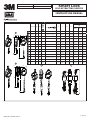 1
1
-
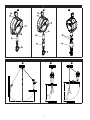 2
2
-
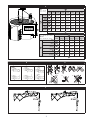 3
3
-
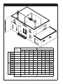 4
4
-
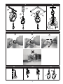 5
5
-
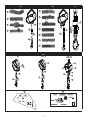 6
6
-
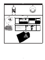 7
7
-
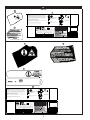 8
8
-
 9
9
-
 10
10
-
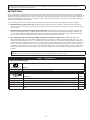 11
11
-
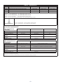 12
12
-
 13
13
-
 14
14
-
 15
15
-
 16
16
-
 17
17
-
 18
18
-
 19
19
-
 20
20
-
 21
21
-
 22
22
-
 23
23
-
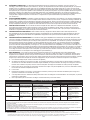 24
24
-
 25
25
-
 26
26
-
 27
27
-
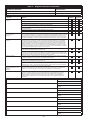 28
28
-
 29
29
-
 30
30
-
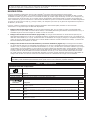 31
31
-
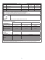 32
32
-
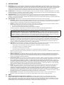 33
33
-
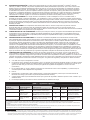 34
34
-
 35
35
-
 36
36
-
 37
37
-
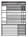 38
38
-
 39
39
-
 40
40


3M DBI-SALA® Ultra-Lok™ Self Retracting Lifeline 3503805, 20 ft (6.1m) Rope, 1 ea Mode d'emploi
- Taper
- Mode d'emploi
dans d''autres langues
Documents connexes
-
3M PROTECTA® Twin-Leg Self Retracting Lifeline Web 3100412, Red, 6 ft. (1.8 m), 1 ea Mode d'emploi
-
-
-
3M 3900109 Mode d'emploi
-
-
-
-
-
3M DBI-SALA® Lad-Saf™ Stainless Steel Cable Lifeline, 1x7 6152100, 1 EA Mode d'emploi
-
3M 3102003 Manuel utilisateur
Autres documents
-
Honeywell Miller MightEvac User Instruction Manual
-
DeLOCK 18894 Fiche technique
-
-
Miller 475 Manuel utilisateur
-
Guardian Diablo Web SRL 2.0 Mode d'emploi
-
 Aptura LT 30 Self-Retracting Lanyard Le manuel du propriétaire
-
 Workman Self-Retracting Lanyard Le manuel du propriétaire
-

