
MALONE
R
MPG351-XLKIT
MALONE
R
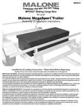
DownLoaderDownLoaderTM
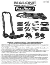
J-STYLE FOLDING KAYAK CARRIER
12’ Safety LinesJawz Universal Adapters Mounting BoltsKayak Carriers Load Straps T-Knobs
60mm
70mm
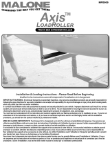
Installation & Loading Instructions - Please Read Before Beginning
Veuillez lire les instructions avant d’entreprendre l’installation et le chargement
1
3
2
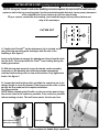
. Insert Mounting Bolt through one hole of a Jawz adapter.
Insert washer and loosely apply a T-knob. See image 2.
. Faites passer le boulon de fixation dans l’un des trous
d’un adaptateur Jawz puis vissez légèrement un bouton
en ‘‘T’’ à la base du boulon. (Figure 2)
. Prior to installation, insert a bolt into the mounting holes in
the bottom of the carriers. Push upward to open the two
mounting hole covers located in the Base pads.
. Insert a Mounting Bolt into one mounting hole from the top
side. Rotate and close the mounting hole cover.
See image 1.
. Insérez un boulon de fixation dans l’un des trous hexagonaux
situés sur le côté supérieur du support.
(Figure 1)
. Place the carrier onto the front cross bar with the boarding
ramp facing out. Swing the Jawz under the cross bar as
shown. See image 3.
. Placez le support sur la barre transversale avant, la rampe
de chargement vers l’extérieur. Faites passer l’adaptateur
Jawz sous la barre transversale, tel qu’indiqué. (Figure 3)
1
Mounting Bolt Washers
Base Pad
Covers
IMPORTANT WARNING: All vehicular transports are potentially hazardous. Any person(s) using Malone products are personally responsible for
following the given directions for use and/or installation and accepts full responsibility for any and all damages or injury of any kind including death,
which may result from their use and/or installation.
It is critical that all Malone racks and accessories be properly and securely attached to your vehicle. Improper attachment could result in a serious
accident, and could cause serious bodily injury or death to you or to others. You are responsible for securing the racks and accessories to your car,
checking the attachment’s prior to use, and periodically inspecting the products for adjustment, wear, and damage.
You must read and understand all of the instructions and cautions supplied with your Malone products(s) prior to installation or use. If you do not
understand all of the instructions and cautions, or, if you have no mechanical experience and are not thoroughly familiar with the installation
procedures, you should have the product installed by a professional installer.
MISE EN GARDE IMPORTANTE: Tout transport d’un chargement sur le toit d’un véhicule est potentiellement dangereux. Une personne qui
utilise les produits Malone doit suivre sans faute les instructions d’installation et d’utilisation fournies et assume l’entière responsabilité pour tout
dommage ou toute blessure, y compris un décès, pouvant résulter d’une telle installation ou utilisation.
Il est essentiel de xer correctement et solidement les supports et les accessoires à votre véhicule. Une mauvaise installation ou attache pourrait
provoquer un accident, entraîner des blessures corporelles graves à vous et aux autres et même causer la mort. Vous avez la responsabilité de
xer solidement les supports et les accessoires à votre véhicule, de vérier l’installation avant l’utilisation et d’inspecter périodiquement le produit
pour déceler tout signe d’usure ou de dommage ou tout problème d’ajustement.
Vous devez lire et comprendre les instructions et les mises en garde fournies avec les produits Malone avant l’installation et l’utilisation. Si vous
ne comprenez pas les instructions et les mises en garde ou si vous ne possédez pas d’expérience en mécanique et ne connaissez pas à fond les
procédures à suivre d’installation, vous devriez faire monter et poser le produit par un installateur professionnel.
This kit converts your standard MPG351 TelosTM to the newer Telos-XLTM .
Attaching to the MPG106 AutoLoaderTM, MPG114 DownLoaderTM, MPG118 J-LoaderTM and the MPG107 SeaWing TM
providing a safe and simple way to side load your kayak
TELOS-XLKIT
KAYAK LIFT ASSIST / EXTENSOIN KIT

IMPORTANT NOTE
Product Warranty & Registration Form
All information is condential and used exclusively by MALONE only.
MALONE
R
MALONE AUTO RACKS 81 County Rd. Ste 1, Westbrook, ME 04092
P: 207.774.9100 F: 207.615.0551
E: support@maloneautoracks.com W: www.maloneautoracks.com
Dear Customer,
Thank you for your purchase of a Malone Product.
In order to be eligible for the Malone Warranty program, we ask that you contact us online at the link provided
below: With-in 30 days of purchase. You can also mail this letter back to the address at the bottom.
• Online: https://maloneautoracks.com/product-registration.php
We will require the information below.
Here is the information collected:
First Name:
Last Name:
Address:
Address2:
City:
State:
Zip:
Country:
Email:
Phone:
Product Description/Name:
Product MPG#
Date Purchased:
Store Where Purchased:
Purchase Price:
Thank you for choosing Malone!

MALONE
R
TELOS-XL
KAYAK LIFT ASSIST / EXTENSOIN KIT
TelosXL Main
Assembly (2)
PART DESCRIPTION PART NUMBER QTY
A 1/4” Socket Head Allen Wrench MPG351, A 1
B Cradle Bearing Assembly MPG351, L 2
C End Cap MPG351, M 2
D Suction Bearing Assembly MPG351, N 2
E Socket Head Screw, Stainless Steel MPG351, E 4
F Extrusion Assembly MPG351, O 2
PARTS INCLUDED
B
C
MALONE
R
MPG351 TELOS
KAYAK LOADING SYSTEM
TM
The Telos attaches to the MPG106, 106M and 106MD AutoLoader
and provides a safe and simple way to side load your kayak.
TM TM
ASSEMBLY (Installing the Cradle Bearing; Suction Bearing and End Cap to the Extrusion Assembly)
1Remove Part D (Suction Bearing Asmb) and Part A (Allen Wrench) from packaging.
Using Part A, loosen the two screws & T-nuts.
Repeat for second Part D.
2
A
E
F
D
Lg Socket Head Allen Wrench (1)
Sm Socket Head Allen Wrench(1)
ASSEMBLY
1). Using the large allen wrench, begin by removing the end-cap at the bottom of the main TelosTM
extrusion. See gure 1.
2). Next, loosen the t-nuts used to secure the suction cup on the backside of the TelosTM extrusion, and
remove it completely. (we’ll replace it with the assembly connector in the next steps) See gure 2 & 3
MALONE
R
MPG351 TELOS
KAYAK LOADING SYSTEM
TM
ASSEMBLY (Installing the Cradle Bearing; Suction Bearing and End Cap to the Extrusion Assembly)
Remove Part C (End Cap) with Part E (Socket Head Screws) from packaging.
11
10
Remove screws and packaging tape. Place Part C on the
end of Part F.
Note: Position Part C with the curved side facing up as
shown.
Using Part A, insert and tighten Part E (both screws).
Repeat for second Part C and Part E assemblies.
This concludes the ASSEMBLY instructions.
12
13
Test and conrm smooth travel of Part B . Push to raise.
Pull locking pin ring to lower.
Repeat for second Part B assembly.
10
9
Align Part B to the front side of Part F. Slide on
until travel is stopped by the lower lock-out.
Pull up on the locking pin ring and slide bearing past
the lower lock-out.
Note: Expect the initial t between Part B and Part F
to be tight. Part B will wear in during use.
9
Locking
Pin
Travel
1
MALONE
R
MPG351 TELOS
KAYAK LOADING SYSTEM
TM
ASSEMBLY (Installing the Cradle Bearing; Suction Bearing and End Cap to the Extrusion Assembly)
Remove Part F (Extrusion Asmb) from packaging.
3
Position Part D (as shown) to the back side of Part F.
Align rst T-nut and slide Part D into channel slot of
Part F. (see image)
Note: T-nut must be loose and straight in order to
properly line-up and insert into the channel slot.
Align second T-nut and slide Part D all the way into
Part F. (see image)
Slide Part D to the mid-point of Part F. Using Part A,
gently tighten both screws.
Repeat for second Part D and Part F assemblies.
Note: The nal mounting position of Part D will be
covered in the INSTALLATION section of the instructions.
4
5
6
Remove Part B (Cradle Bearing Asmb) from packaging.
7
Position Part B to the front side of Part F. (see image)
8
T-nuts
PART DESCRIPTION PART NUMBER QTY
A 1/4” Socket Head Allen Wrench MPG351, A 1
B Cradle Bearing Assembly MPG351, L 2
C End Cap MPG351, M 2
D Suction Bearing Assembly MPG351, N 2
E Socket Head Screw, Stainless Steel MPG351, E 4
F Extrusion Assembly MPG351, O 2
PARTS INCLUDED
B
C
MALONE
R
MPG351 TELOS
KAYAK LOADING SYSTEM
TM
The Telos attaches to the MPG106, 106M and 106MD AutoLoader
and provides a safe and simple way to side load your kayak.
TM TM
ASSEMBLY (Installing the Cradle Bearing; Suction Bearing and End Cap to the Extrusion Assembly)
1Remove Part D (Suction Bearing Asmb) and Part A (Allen Wrench) from packaging.
Using Part A, loosen the two screws & T-nuts.
Repeat for second Part D.
2
A
E
F
D
MPG350CLIP Quick-Connect Bracket Installation Instruction
Step 1: Position bracket as shown over
the slot in the rear of the top
plate.
Step 2: Insert screws and tighten.
Note: Firmly press each screw
into hole before screwing into
bracket.
Step 3: Correctly installed bracket as
viewed from the forward side.
Step 4: Correctly installed bracket as
viewed from the rear side.
The TelosTM attaches to the MPG106 AutoLoaderTM, MPG114 DownLoaderTM and the MPG118 J-LoaderTM
providing a safe and simple way to side load your kayak
PARTS INCLUDED
PART DESCRIPTION PART NUMBER QTY
A 1/4” Socket Head Allen Wrench MPG351, A 1
B Cradle Bearing Assembly MPG351, L 2
C End Cap MPG351, M 2
D Suction Bearing Assembly MPG351, N 2
E Socket Head Screw, Stainless Steel MPG351, E 4
F Extrusion Assembly MPG351, O 2
PARTS INCLUDED
B
C
MALONE
R
MPG351 TELOS
KAYAK LOADING SYSTEM
TM
The Telos attaches to the MPG106, 106M and 106MD AutoLoader
and provides a safe and simple way to side load your kayak.
TM TM
ASSEMBLY (Installing the Cradle Bearing; Suction Bearing and End Cap to the Extrusion Assembly)
1Remove Part D (Suction Bearing Asmb) and Part A (Allen Wrench) from packaging.
Using Part A, loosen the two screws & T-nuts.
Repeat for second Part D.
2
A
E
F
D
Pt#3002CLIP Quick-Connect Bracket Installation Instruction
PART DESCRIPTION PART NUMBER QTY
A 1/4” Socket Head Allen Wrench MPG351, A 1
B Cradle Bearing Assembly MPG351, L 2
C End Cap MPG351, M 2
D Suction Bearing Assembly MPG351, N 2
E Socket Head Screw, Stainless Steel MPG351, E 4
F Extrusion Assembly MPG351, O 2
PARTS INCLUDED
B
C
MALONE
R
MPG351 TELOS
KAYAK LOADING SYSTEM
TM
The Telos attaches to the MPG106, 106M and 106MD AutoLoader
and provides a safe and simple way to side load your kayak.
TM TM
ASSEMBLY (Installing the Cradle Bearing; Suction Bearing and End Cap to the Extrusion Assembly)
1Remove Part D (Suction Bearing Asmb) and Part A (Allen Wrench) from packaging.
Using Part A, loosen the two screws & T-nuts.
Repeat for second Part D.
2
A
E
F
D
MALONE
R
MPG351 TELOS
KAYAK LOADING SYSTEM
TM
ASSEMBLY (Installing the Cradle Bearing; Suction Bearing and End Cap to the Extrusion Assembly)
Remove Part F (Extrusion Asmb) from packaging.
3
Position Part D (as shown) to the back side of Part F.
Align rst T-nut and slide Part D into channel slot of
Part F. (see image)
Note: T-nut must be loose and straight in order to
properly line-up and insert into the channel slot.
Align second T-nut and slide Part D all the way into
Part F. (see image)
Slide Part D to the mid-point of Part F. Using Part A,
gently tighten both screws.
Repeat for second Part D and Part F assemblies.
Note: The nal mounting position of Part D will be
covered in the INSTALLATION section of the instructions.
4
5
6
Remove Part B (Cradle Bearing Asmb) from packaging.
7
Position Part B to the front side of Part F. (see image)
8
T-nuts
2
MALONE
R
MPG351 TELOS
KAYAK LOADING SYSTEM
TM
ASSEMBLY (Installing the Cradle Bearing; Suction Bearing and End Cap to the Extrusion Assembly)
Remove Part F (Extrusion Asmb) from packaging.
3
Position Part D (as shown) to the back side of Part F.
Align rst T-nut and slide Part D into channel slot of
Part F. (see image)
Note: T-nut must be loose and straight in order to
properly line-up and insert into the channel slot.
Align second T-nut and slide Part D all the way into
Part F. (see image)
Slide Part D to the mid-point of Part F. Using Part A,
gently tighten both screws.
Repeat for second Part D and Part F assemblies.
Note: The nal mounting position of Part D will be
covered in the INSTALLATION section of the instructions.
4
5
6
Remove Part B (Cradle Bearing Asmb) from packaging.
7
Position Part B to the front side of Part F. (see image)
8
T-nuts
PART DESCRIPTION PART NUMBER QTY
A 1/4” Socket Head Allen Wrench MPG351, A 1
B Cradle Bearing Assembly MPG351, L 2
C End Cap MPG351, M 2
D Suction Bearing Assembly MPG351, N 2
E Socket Head Screw, Stainless Steel MPG351, E 4
F Extrusion Assembly MPG351, O 2
PARTS INCLUDED
B
C
MALONE
R
MPG351 TELOS
KAYAK LOADING SYSTEM
TM
The Telos attaches to the MPG106, 106M and 106MD AutoLoader
and provides a safe and simple way to side load your kayak.
TM TM
ASSEMBLY (Installing the Cradle Bearing; Suction Bearing and End Cap to the Extrusion Assembly)
1Remove Part D (Suction Bearing Asmb) and Part A (Allen Wrench) from packaging.
Using Part A, loosen the two screws & T-nuts.
Repeat for second Part D.
2
A
E
F
D
MPG350CLIP Quick-Connect Bracket Installation Instruction
Step 1: Position bracket as shown over
the slot in the rear of the top
plate.
Step 2: Insert screws and tighten.
Note: Firmly press each screw
into hole before screwing into
bracket.
Step 3: Correctly installed bracket as
viewed from the forward side.
Step 4: Correctly installed bracket as
viewed from the rear side.
The TelosTM attaches to the MPG106 AutoLoaderTM, MPG114 DownLoaderTM and the MPG118 J-LoaderTM
providing a safe and simple way to side load your kayak
PARTS INCLUDED
PART DESCRIPTION PART NUMBER QTY
A 1/4” Socket Head Allen Wrench MPG351, A 1
B Cradle Bearing Assembly MPG351, L 2
C End Cap MPG351, M 2
D Suction Bearing Assembly MPG351, N 2
E Socket Head Screw, Stainless Steel MPG351, E 4
F Extrusion Assembly MPG351, O 2
PARTS INCLUDED
B
C
MALONE
R
MPG351 TELOS
KAYAK LOADING SYSTEM
TM
The Telos attaches to the MPG106, 106M and 106MD AutoLoader
and provides a safe and simple way to side load your kayak.
TM TM
ASSEMBLY (Installing the Cradle Bearing; Suction Bearing and End Cap to the Extrusion Assembly)
1Remove Part D (Suction Bearing Asmb) and Part A (Allen Wrench) from packaging.
Using Part A, loosen the two screws & T-nuts.
Repeat for second Part D.
2
A
E
F
D
Pt#3002CLIP Quick-Connect Bracket Installation Instruction
PART DESCRIPTION PART NUMBER QTY
A 1/4” Socket Head Allen Wrench MPG351, A 1
B Cradle Bearing Assembly MPG351, L 2
C End Cap MPG351, M 2
D Suction Bearing Assembly MPG351, N 2
E Socket Head Screw, Stainless Steel MPG351, E 4
F Extrusion Assembly MPG351, O 2
PARTS INCLUDED
B
C
MALONE
R
MPG351 TELOS
KAYAK LOADING SYSTEM
TM
The Telos attaches to the MPG106, 106M and 106MD AutoLoader
and provides a safe and simple way to side load your kayak.
TM TM
ASSEMBLY (Installing the Cradle Bearing; Suction Bearing and End Cap to the Extrusion Assembly)
1Remove Part D (Suction Bearing Asmb) and Part A (Allen Wrench) from packaging.
Using Part A, loosen the two screws & T-nuts.
Repeat for second Part D.
2
A
E
F
D
PART DESCRIPTION PART NUMBER QTY
A 1/4” Socket Head Allen Wrench MPG351, A 1
B Cradle Bearing Assembly MPG351, L 2
C End Cap MPG351, M 2
D Suction Bearing Assembly MPG351, N 2
E Socket Head Screw, Stainless Steel MPG351, E 4
F Extrusion Assembly MPG351, O 2
PARTS INCLUDED
B
C
MALONE
R
MPG351 TELOS
KAYAK LOADING SYSTEM
TM
The Telos attaches to the MPG106, 106M and 106MD AutoLoader
and provides a safe and simple way to side load your kayak.
TM TM
ASSEMBLY (Installing the Cradle Bearing; Suction Bearing and End Cap to the Extrusion Assembly)
1Remove Part D (Suction Bearing Asmb) and Part A (Allen Wrench) from packaging.
Using Part A, loosen the two screws & T-nuts.
Repeat for second Part D.
2
A
E
F
D
PART DESCRIPTION PART NUMBER QTY
A 1/4” Socket Head Allen Wrench MPG351, A 1
B Cradle Bearing Assembly MPG351, L 2
C End Cap MPG351, M 2
D Suction Bearing Assembly MPG351, N 2
E Socket Head Screw, Stainless Steel MPG351, E 4
F Extrusion Assembly MPG351, O 2
PARTS INCLUDED
B
C
MALONE
R
MPG351 TELOS
KAYAK LOADING SYSTEM
TM
The Telos attaches to the MPG106, 106M and 106MD AutoLoader
and provides a safe and simple way to side load your kayak.
TM TM
ASSEMBLY (Installing the Cradle Bearing; Suction Bearing and End Cap to the Extrusion Assembly)
1Remove Part D (Suction Bearing Asmb) and Part A (Allen Wrench) from packaging.
Using Part A, loosen the two screws & T-nuts.
Repeat for second Part D.
2
A
E
F
D
MALONE
R
MPG351 TELOS
KAYAK LOADING SYSTEM
TM
ASSEMBLY (Installing the Cradle Bearing; Suction Bearing and End Cap to the Extrusion Assembly)
Remove Part F (Extrusion Asmb) from packaging.
3
Position Part D (as shown) to the back side of Part F.
Align rst T-nut and slide Part D into channel slot of
Part F. (see image)
Note: T-nut must be loose and straight in order to
properly line-up and insert into the channel slot.
Align second T-nut and slide Part D all the way into
Part F. (see image)
Slide Part D to the mid-point of Part F. Using Part A,
gently tighten both screws.
Repeat for second Part D and Part F assemblies.
Note: The nal mounting position of Part D will be
covered in the INSTALLATION section of the instructions.
4
5
6
Remove Part B (Cradle Bearing Asmb) from packaging.
7
Position Part B to the front side of Part F. (see image)
8
T-nuts
MALONE
R
MPG351 TELOS
KAYAK LOADING SYSTEM
TM
ASSEMBLY (Installing the Cradle Bearing; Suction Bearing and End Cap to the Extrusion Assembly)
Remove Part F (Extrusion Asmb) from packaging.
3
Position Part D (as shown) to the back side of Part F.
Align rst T-nut and slide Part D into channel slot of
Part F. (see image)
Note: T-nut must be loose and straight in order to
properly line-up and insert into the channel slot.
Align second T-nut and slide Part D all the way into
Part F. (see image)
Slide Part D to the mid-point of Part F. Using Part A,
gently tighten both screws.
Repeat for second Part D and Part F assemblies.
Note: The nal mounting position of Part D will be
covered in the INSTALLATION section of the instructions.
4
5
6
Remove Part B (Cradle Bearing Asmb) from packaging.
7
Position Part B to the front side of Part F. (see image)
8
T-nuts
3
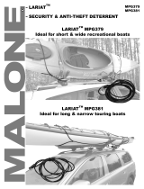
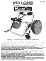
Assembly Connector (4)
Connector Hardware (8)
3). Insert the connector hardware through the assembly connector and loosely apply the t-nut. NOTE
the direction / shape of the t-nut installation*. The Flange should face downwards. Repeat with
remaining 3 connectors. See gure 4.
45
4). With the hardware installed, align
the t-nuts and slide the rst
connector into the channel slot on
the back of the extrusion.
See image 5.
*
Visit www.maloneautoracks.com/Replacement-Parts for all of your spare part needs
SeaWingTM Fit Kit (1)
REMOVE ME
X
Align with hole in
SeaWingtm
DRILL HERE
SeaWingtm Outer Edge
PART DESCRIPTION PART NUMBER QTY
A 1/4” Socket Head Allen Wrench MPG351, A 1
B Cradle Bearing Assembly MPG351, L 2
C End Cap MPG351, M 2
D Suction Bearing Assembly MPG351, N 2
E Socket Head Screw, Stainless Steel MPG351, E 4
F Extrusion Assembly MPG351, O 2
PARTS INCLUDED
B
C
MALONE
R
MPG351 TELOS
KAYAK LOADING SYSTEM
TM
The Telos attaches to the MPG106, 106M and 106MD AutoLoader
and provides a safe and simple way to side load your kayak.
TM TM
ASSEMBLY (Installing the Cradle Bearing; Suction Bearing and End Cap to the Extrusion Assembly)
1Remove Part D (Suction Bearing Asmb) and Part A (Allen Wrench) from packaging.
Using Part A, loosen the two screws & T-nuts.
Repeat for second Part D.
2
A
E
F
D
Small Socket Head
Allen Wrench (1)
SeaWingTM Pin
Template (1)
Small Socket Head
Screw (2)

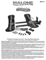
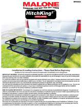
This concludes the assembly.
ASSEMBLY CONT.
5). Slide the rst connector 22” up the extrusion and secure it place with the small allen wrench.
See image 6.
6
22”
7
8”
6). Repeat with the second connector, measuring 8” from the bottom. Secure it place with the small
allen wrench. Finish and secure with the end cap on the bottom of the extrusion. Be sure to check that
all bolts are fully tightened. See image 7.
7). With the assembly connectors in place slide the TelosXLTM main assembly in from the bottom,
passing through both connectors. Use the hand knob to loosen & secure tension making it slide easier.
Tighten fully when reaching desired length.
8
9

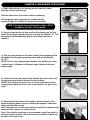
First, conrm that the kayak carriers are secure and located directly
inside the cross rail towers. You’ll dress the straps as described in
your kayak carriers instructions.
NOTE: NEVER MOUNT THE CARRIERS OUTSIDE OF THE
CROSS RAIL TOWERS. THIS APPLIES TO BOTH FACTORY
AND AFTER-MARKET CROSS RAILS.
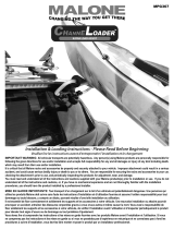
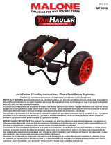
1). Position the TelosXLTM so the attachment clip is located on the
rear of the top mounting plate and aligns with the slot in the
carriers loading ramp. See gure 1.
Insert and pull-down to engage the attachment clip.
INSTALLATION & USE (Installing the TelosXLTM to the Loading Ramp of the MPG106, MPG114, MPG118)
2). With the top plate secured, loosen the hand knobs on the
assembly connector on the backside and slide the extender
downwards until the black locking collar is clear of the bottom. Fully
tighten the knobs. See gure 2
1
3). Loosen the black locking collar and slide the extension out to the desired length to reach the
ground. Twist to secure the collar in place and ip the foot pedal out to complete installation.
See gures below.
NOTE: When extending the TelosXLTM to the ground we want to keep the unit as close to the vehicle as
possible, or as vertical as possible without making contact. This will insure easier function and use.
Twist collar to loosen
and secure extension.
Foot pedal
2
This concludes the J-Style installation.

INSTALLATION & USE (Installing the TelosXLTM to the MPG107 SeaWingTM)
REMOVE ME
X
Align with hole in
SeaWingtm
DRILL HERE
SeaWingtm Outer Edge
NOTE: Using the TelosXLTM with older SeaWingTM carriers requires the user to drill a small hole and
replace a bolt in the top mounting plate. Use the provided template below to insure proper placement
of the required hole if your carriers do not have one already.
IF your carriers contain this hole already, just install the longer bolt as pictured below and
skip to the next steps.
CUT ME OUT
1). First, remove the template above
and carefully cut out the center hole
marked ‘remove’.
2). Place the template over the
SeaWingTM outer hole as pictured
below and mark the location of the
required hole.
3).Using a 3/8” bit, carefully drill
the hole into the SeaWingTM. Repeat
these steps for the 3 remaining
holes.
4). Remove the top bolt securing the
attachment clip and replace it with
the longer one provided.
This new bolt will act as a pin,
preventing the Telos from moving
during the loading procedure.
First, conrm that the kayak carriers are secure and located directly
inside the cross rail towers. You’ll dress the straps as described in
your kayak carriers instructions.
NOTE: NEVER MOUNT THE CARRIERS OUTSIDE OF THE
CROSS RAIL TOWERS. THIS APPLIES TO BOTH FACTORY
AND AFTER-MARKET CROSS RAILS.

3). Loosen the black locking collar and slide the extension out to the
desired length to reach the ground. Twist to secure the collar in place
and ip the foot pedal out to complete installation.
See gures below.
NOTE: When extending the TelosXLTM to the ground we want to keep
the unit as close to the vehicle as possible, or as vertical as possible
without making contact. This will insure easier function and use.
This concludes the Saddle Style installation.
Twist collar to loosen
and secure extension.
Foot pedal
REMOVE ME
X
Align with hole in
SeaWingtm
DRILL HERE
SeaWingtm Outer Edge
CUT ME OUT
1). Position the TelosXLTM so the attachment clip is located on the
rear of the top mounting plate and aligns with the slot in the
SeaWingTM. See gure 1.
Insert and pull-down to engage the attachment clip and seat the bolt
into the hole. The bolt prevents the TelosTM from rotating during the
loading procedures.
2). With the top plate secured, loosen the knobs on the assembly
connector on the backside and slide the extender downwards
until the black locking collar is clear of the bottom. Fully tighten the
knobs. See gure 2
1
2
3
INSTALLATION & USE (Installing the TelosXLTM to the MPG107 SeaWingTM)
NOTE: Using the TelosXLTM with older SeaWingTM carriers requires the user to drill a small hole and
replace a bolt in the top mounting plate. Use the provided template below to insure proper placement
of the required hole if your carriers do not have one already.
IF your carriers contain this hole already, just install the longer bolt as pictured below and
skip to the next steps.

LOADING & UNLOADING YOUR KAYAK
1). Begin with pulling up on locking pin and lower the cradle
bearings to their lowest point.
Fold the side mirror in to avoid contact and damage.
Lift and gently place kayak into the cradles with the
cockpit facing out. Position the kayak so it is vertical.
NOTE: If the kayak does not t into the cradles - STOP.
Call Malone (207).887.1070 for details.
2). Grip the lower section of one cradle while stepping on the foot
pedal. Gently apply upward pressure and raise the kayak 6”- 8”. The
mechanism will automatically lock in place when pressure is
released.
3). Grip the lower section of the other cradle (while stepping on the
foot pedal). Gently apply upward pressure and raise the kayak
12”-16”.
NOTE: This is only a approximate distance. You will nd your own
‘comfort zone’ of distance to lift based upon individual size and
kayak weight.
4). Continue to raise the kayak in this fashion (front then rear) until
the top locking position is reached for both cradles.
NOTE: This process should be done in a slow controlled manner.
Avoid getting either the front or rear of the kayak at too great of an
angle.
5). Standing directly between the cradles, grip the bottom of the
kayak and gently push up and in, allowing the kayak to rotate and
drop down into the carriers.
Note: Sometimes it is easier and requires less effort to maneuver the
kayak into the carriers one side at a time.
Note: If the vehicle is too high, we recommend a small foot stool be
used during this process. The unit should be portable so that it can
be taken to the put-in site.
LOADING & UNLOADING (Raising, Lowering & Loading the Kayak )
MALONE
R
MPG351 TELOS
KAYAK LOADING SYSTEM
TM
Grip the bottom of the rear cradle and gently apply
upward pressure. Raise the kayak approximately 12”
to 16”.
Note: This is only an approximate distance. You will
nd your own “comfort zone” of distance to lift based
upon individual size and kayak weight.
22
23 Continue to raise the kayak in this fashion (front then
rear) until the top locking position is reached for both
the front and rear cradles.
Note: The process of raising the kayak should be done
in a slow controlled manner. Avoid getting either the
front or rear of the kayak at too great of an angle.
24 Standing directly between the cradles, grip the bottom
of the kayak and gently push up and in, allowing the
kayak to rotate and drop down into the AutoLoaders.
Note: Sometimes it is easier and requires less eort to
maneuver the kayak into the carriers one side at a time.
Note: If the vehicle is too high, we recommend a small
foot stool be used during this process. The unit should
be portable so that it can be taken to the put-in site.
TM
25 With the kayak now in place in the AutoLoaders, remove
each Telos assembly.
Lift up on the tab xed to the suction cup on Part D. This
will release the vacuum. Lift the entire Telos assembly
slightly up and outward to release the attachment pin.
Store in the vehicle when not in use.
TM
TM
TM
MALONE
R
MPG351 TELOS
KAYAK LOADING SYSTEM
TM
INSTALLATION (Installing the Telos to the AutoLoader )
TM
TM
20 Pull up on locking pin rings and lower Part B bearings
to their lowest settings.
Fold the side mirror in to avoid contact & damage.
Lift and gently place kayak into the cradles with the
cockpit facing out. Position the kayak so it is vertical.
Note: If the kayak does not t into the cradles - STOP.
Call Malone (1-800-295-0042 x 206) for details.
21 Grip the lower section of the front cradle and gently
apply upward pressure. Raise the kayak approximately
6” to 8”. The mechanism will automatically lock in place
when the pressure is released.
Note: This travel should be done slowly and gently to
avoid damage to the vehicle and/or kayak.
Select the strongest part of the vehicle’s side panel to
locate Part D. Slide Part D into place and tighten using
Part A.
Note: Locate Part D close to contour changes in the
vehicle’s side panels. These areas are stronger than
large open at areas and can absorb more pressure.
18
19 Apply gentle pressure to Part D. The suction cup will
engage and hold the Telos in place.
Note: Dust and dirt must be removed from the vehicle’s
side panel prior to Part D placement. Failure to do so
can result in side panel abrasion.
Repeat steps 15, 16, 17, 18 and 19 for second Telos.
This concludes the INSTALLATION instructions.
TM
TM
LOADING & UNLOADING (Raising, Lowering & Loading the Kayak )
LOADING & UNLOADING (Raising, Lowering & Loading the Kayak )
MALONE
R
MPG351 TELOS
KAYAK LOADING SYSTEM
TM
Grip the bottom of the rear cradle and gently apply
upward pressure. Raise the kayak approximately 12”
to 16”.
Note: This is only an approximate distance. You will
nd your own “comfort zone” of distance to lift based
upon individual size and kayak weight.
22
23 Continue to raise the kayak in this fashion (front then
rear) until the top locking position is reached for both
the front and rear cradles.
Note: The process of raising the kayak should be done
in a slow controlled manner. Avoid getting either the
front or rear of the kayak at too great of an angle.
24 Standing directly between the cradles, grip the bottom
of the kayak and gently push up and in, allowing the
kayak to rotate and drop down into the AutoLoaders.
Note: Sometimes it is easier and requires less eort to
maneuver the kayak into the carriers one side at a time.
Note: If the vehicle is too high, we recommend a small
foot stool be used during this process. The unit should
be portable so that it can be taken to the put-in site.
TM
25 With the kayak now in place in the AutoLoaders, remove
each Telos assembly.
Lift up on the tab xed to the suction cup on Part D. This
will release the vacuum. Lift the entire Telos assembly
slightly up and outward to release the attachment pin.
Store in the vehicle when not in use.
TM
TM
TM
kayak carriers.
With the kayak now loaded into the carriers, remove
each TelosTM assembly.
RELEASING THE SUCTION BEARING ASSEMBLY
Store in the vehicle when not in use.

6). With the kayak now loaded into the carriers, remove the TelosXLTM
assembly from the vehicle and dress the straps as dened in your
carriers instructions.
LOADING & UNLOADING YOUR KAYAK CONT.
LOADING & UNLOADING (Raising, Lowering & Loading the Kayak)
MALONE
R
MPG351 TELOS
KAYAK LOADING SYSTEM
TM
TM
Dress the load straps as dened by steps 13, 14 and 15
of the AutoLoader instructions.
26
TM
28 Grip the lower section of the front cradle and gently
apply upward pressure. With the other hand, pull up
on the locking pin ring and slowly lower the kayak 6”
to 8”.
Release the locking pin ring to stop downward travel.
Repeat process for rear cradle. Continue to lower the
kayak in this manner until the bottom cradle positions
are reached.
29 Remove the kayak from the Telos cradles.
Remove the Telos assemblies and store away.
Remove the load straps.
TM
TM
27 To lower the kayak, unbuckle the straps and install both
Telos assemblies as described in steps 15, 16, and 19.
Raise both Part B cradle bearings to the top position.
Push up and pull out kayak so that it slides down the
AutoLoader boarding ramps and into the Telos cradles.
TM
TM
TM
Dress the load straps as dened in the steps of your
kayak carrier instructions.
carriers boarding ramp and into the TelosTM cradles
Store in the vehicle when not in use.
LOADING & UNLOADING (Raising, Lowering & Loading the Kayak )
MALONE
R
MPG351 TELOS
KAYAK LOADING SYSTEM
TM
Grip the bottom of the rear cradle and gently apply
upward pressure. Raise the kayak approximately 12”
to 16”.
Note: This is only an approximate distance. You will
nd your own “comfort zone” of distance to lift based
upon individual size and kayak weight.
22
23 Continue to raise the kayak in this fashion (front then
rear) until the top locking position is reached for both
the front and rear cradles.
Note: The process of raising the kayak should be done
in a slow controlled manner. Avoid getting either the
front or rear of the kayak at too great of an angle.
24 Standing directly between the cradles, grip the bottom
of the kayak and gently push up and in, allowing the
kayak to rotate and drop down into the AutoLoaders.
Note: Sometimes it is easier and requires less eort to
maneuver the kayak into the carriers one side at a time.
Note: If the vehicle is too high, we recommend a small
foot stool be used during this process. The unit should
be portable so that it can be taken to the put-in site.
TM
25 With the kayak now in place in the AutoLoaders, remove
each Telos assembly.
Lift up on the tab xed to the suction cup on Part D. This
will release the vacuum. Lift the entire Telos assembly
slightly up and outward to release the attachment pin.
Store in the vehicle when not in use.
TM
TM
TM
MALONE
R
MPG351 TELOS
KAYAK LOADING SYSTEM
TM
INSTALLATION (Installing the Telos to the AutoLoader )
TM
TM
20 Pull up on locking pin rings and lower Part B bearings
to their lowest settings.
Fold the side mirror in to avoid contact & damage.
Lift and gently place kayak into the cradles with the
cockpit facing out. Position the kayak so it is vertical.
Note: If the kayak does not t into the cradles - STOP.
Call Malone (1-800-295-0042 x 206) for details.
21 Grip the lower section of the front cradle and gently
apply upward pressure. Raise the kayak approximately
6” to 8”. The mechanism will automatically lock in place
when the pressure is released.
Note: This travel should be done slowly and gently to
avoid damage to the vehicle and/or kayak.
Select the strongest part of the vehicle’s side panel to
locate Part D. Slide Part D into place and tighten using
Part A.
Note: Locate Part D close to contour changes in the
vehicle’s side panels. These areas are stronger than
large open at areas and can absorb more pressure.
18
19 Apply gentle pressure to Part D. The suction cup will
engage and hold the Telos in place.
Note: Dust and dirt must be removed from the vehicle’s
side panel prior to Part D placement. Failure to do so
can result in side panel abrasion.
Repeat steps 15, 16, 17, 18 and 19 for second Telos.
This concludes the INSTALLATION instructions.
TM
TM
LOADING & UNLOADING (Raising, Lowering & Loading the Kayak )
LOADING & UNLOADING (Raising, Lowering & Loading the Kayak )
MALONE
R
MPG351 TELOS
KAYAK LOADING SYSTEM
TM
Grip the bottom of the rear cradle and gently apply
upward pressure. Raise the kayak approximately 12”
to 16”.
Note: This is only an approximate distance. You will
nd your own “comfort zone” of distance to lift based
upon individual size and kayak weight.
22
23 Continue to raise the kayak in this fashion (front then
rear) until the top locking position is reached for both
the front and rear cradles.
Note: The process of raising the kayak should be done
in a slow controlled manner. Avoid getting either the
front or rear of the kayak at too great of an angle.
24 Standing directly between the cradles, grip the bottom
of the kayak and gently push up and in, allowing the
kayak to rotate and drop down into the AutoLoaders.
Note: Sometimes it is easier and requires less eort to
maneuver the kayak into the carriers one side at a time.
Note: If the vehicle is too high, we recommend a small
foot stool be used during this process. The unit should
be portable so that it can be taken to the put-in site.
TM
25 With the kayak now in place in the AutoLoaders, remove
each Telos assembly.
Lift up on the tab xed to the suction cup on Part D. This
will release the vacuum. Lift the entire Telos assembly
slightly up and outward to release the attachment pin.
Store in the vehicle when not in use.
TM
TM
TM
kayak carriers.
With the kayak now loaded into the carriers, remove
each TelosTM assembly.
RELEASING THE SUCTION BEARING ASSEMBLY
Store in the vehicle when not in use.
1). To lower the kayak, unbuckle the straps and install both TelosXLTM
assembles as described in the beginning steps.
Raise both cradles to the top position and carefully push up and pull
out the kayak so it slides down the loading ramp of the carrier and
into the TelosXLTM cradles.
2). Grip the lower section of one cradle and gently apply upward
pressure. With the other hand, pull the locking pin out and slowly
lower the kayak 6”to 8”.
Release the locking pin to stop downward travel.
Repeat process for other cradle. Continue to lower the kayak in this
manner until the cradles reach the bottom.
3). Remove the kayak from the TelsoXLTM cradles
Remove the TelosXLTM assemblies and store away.
Remove all load straps.
Compress size & Store in the vehicle when not in use.

MALONE AUTO RACKS 81 County Rd. Ste 1, Westbrook, ME 04092
P: 207.774.9100 F: 207.615.0551
E: support@maloneautoracks.com W: www.maloneautoracks.com
Limited Lifetime Warranty
The Malone Auto Racks (Malone) Limited Lifetime Warranty covers certain Malone-brand products that have been specically
identied for inclusion in the program and is effective for as long as the original retail purchaser owns the product. This warranty is
terminated when the original retail purchaser sells or otherwise transfers the product to any other person or entity.
Subject to the limitations and exclusions described in this warranty, Malone will remedy defects in materials and/or workmanship
by repairing or replacing, at its option, a defective product without charge for parts or labor. Malone may elect, at its option, not to
repair or replace a defective product but rather issue to the original retail purchaser a refund equal to the purchase price paid for the
product, or credit to be used toward the purchase of a replacement Malone product.
This warranty does not cover, and no warranty is given for defects or problems caused by normal wear and tear, which includes,
but is not limited to, surface (aesthetic) metal corrosion, scratches, dents, deformities, accidents, unlawful vehicle operation, or any
modication of a product not performed or authorized in writing by Malone.
In addition, this warranty does not cover problems resulting from conditions beyond Malone’s control including, but not limited to,
theft, misuse, overloading, or failure to assemble, mount or use the product in accordance with Malone’s written instructions or
guidelines included with the product provided to the original retail purchaser.
No warranty is given for Malone products purchased outside of the continental United States, Canada and Mexico.
If the product is believed to be defective, the original retail purchaser should contact the Malone dealer from whom it was purchased,
who will give the original retail purchaser instructions on how to proceed. If the original retail purchaser is unable to contact the
Malone dealer, or the dealer is not able to remedy the defect, the original retail purchaser should contact Malone by email at
In the event that the product must be returned to Malone, a technician at the email address above will provide the original purchaser
with return shipping instructions. The original purchaser will be responsible for the cost of mailing the product to Malone. In order
to be eligible to receive any remedy under this warranty, a copy of the original purchase receipt, a description of the defect and a
return address must be provided.
Disclaimer of Liability
Repair or replacement of a defective product, or the issue of a refund or credit (as determined by Malone) is the original retail
purchaser’s sole and exclusive remedy under this warranty. Damage to original purchaser’s vehicle, cargo, or property, and/ or to
any other person or property is not covered by this warranty.
This warranty is expressly made in lieu of any and all other warranties, express or implied, including the warranties of merchantability
and tness of a particular purpose
Malone’s sole liability to any purchaser is limited to the remedy set forth above. In no event will Malone be liable for any direct,
indirect, consequential, incidental, special, exemplary, or punitive damages , or, for any other damages of any kind or nature
(including but not limited to, lost prots, lost income or lost sales).
Some states do not allow the exclusion or limitation of incidental or consequential damages, so the above limitations may not be
applicable.
In addition, all vehicular transports are potentially hazardous. Any person(s) using Malone products are personally responsible for
following the given directions for use and/or installation and accepts full responsibility for any and all damages or injury of any kind
including death, which may result from their use and/or installation.
MALONE
R

MALONE AUTO RACKS 81 County Rd. Ste 1, Westbrook, ME 04092
P: 207.774.9100 F: 207.615.0551
E: support@maloneautoracks.com W: www.maloneautoracks.com
MALONE
R
Garantie à vie limitée
La garantie à vie limitée de Malone Auto Racks (Malone) couvre certains produits de marque Malone expressément désignés pour
être inclus dans ce programme et est valide tant que l’acheteur original est propriétaire du produit. Cette garantie prend n lorsque
l’acheteur original vend ou cède le produit à une autre personne ou entité.
Sous réserve des restrictions et exclusions prévues dans la garantie, Malone corrigera toute défectuosité matérielle et/ou tout défaut
de fabrication en réparant ou en remplaçant, à sa discrétion, un produit défectueux sans frais pour ce qui est des pièces et de la
main-d’oeuvre. Malone peut décider, à son choix, de ne pas réparer ou remplacer un produit défectueux, mais plutôt d’accorder à
l’acheteur original un remboursement d’un montant égal au prix d’achat pour le produit ou encore un crédit pour l’achat d’un produit
de remplacement de marque Malone.
La présente garantie ne couvre pas les défauts et les problèmes résultant d’une usure normale et aucune garantie n’est offerte à cet
égard, notamment en cas de corrosion du métal en surface (esthétique), d’égratignures, de bosses, de déformations, d’accident,
d’une utilisation illégale du véhicule ou de toute modication du produit qui n’est pas effectuée ou autorisée par écrit par Malone.
En outre, la garantie ne couvre pas les problèmes résultant de circonstances échappant au contrôle de Malone, y compris,
notamment, résultant d’un vol, d’un usage abusif ou d’une surcharge ou encore d’un assemblage, d’une installation ou d’une
utilisation du produit ne respectant pas les instructions écrites de Malone fournies à l’achat à l’acheteur original.
Aucune garantie n’est offerte pour des produits Malone achetés à l’extérieur du territoire continental des États-Unis, du Canada ou
du Mexique.
Si le produit semble défectueux, l’acheteur original doit contacter le détaillant Malone où il a fait son achat et celui-ci lui fournira
des renseignements sur la démarche à suivre. Si l’acheteur original ne réussit pas à contacter le détaillant Malone ou encore si le
détaillant est incapable de remédier à la défectuosité, l’acheteur original doit communiquer directement avec Malone par courriel à
l’adresse suivante : [email protected].
Dans le cas où le produit doit être retourné à Malone, un technicien contacté à l’adresse courriel ci-dessus fournira à l’acheteur
original les instructions à suivre pour l’expédition du produit. L’acheteur original devra assumer les frais d’expédition à Malone.
Pour qu’une demande soit admissible aux termes de la présente garantie, il faut envoyer à Malone une copie du reçu de l’acheteur
original, une description de la défectuosité et une adresse de retour.
Exonération de responsabilité
La réparation ou le remplacement du produit défectueux ou encore la remise d’un remboursement ou d’un crédit (tel que déterminé
par Malone) constitue le seul et exclusif dédommagement offert à l’acheteur original aux termes de la présente garantie. Les
dommages causés au véhicule de l’acheteur original, à un chargement, à ses biens et/ou à toute autre personne ou tout autre bien
ne sont pas couverts par cette garantie.
Cette garantie est octroyée expressément an de remplacer toute autre garantie expresse ou implicite, y compris toute garantie de
qualité marchande ou de conformité pour un usage particulier.
L’unique responsabilité de Malone envers l’acheteur se limite aux dédommagements indiqués ci-dessus. Malone ne pourra en
aucun cas être tenu responsable des dommages directs, indirects, consécutifs, spéciaux, exemplaires ou punitifs ou de tout autre
dommage de quelque nature que ce soit (y compris notamment une perte de prots, de revenus ou de ventes).
L’exclusion ou la limitation des dommages indirects ou consécutifs n’étant pas permise à certains endroits, les limitations indiquées
ci-dessus peuvent ne pas s’appliquer.
En outre, tous les transports par véhicule comportent des risques potentiels. Toute personne utilisant un produit Malone est donc
personnellement responsable de suivre les instructions fournies pour son utilisation et/ou son installation et accepte l’entière
responsabilité pour tout dommage ou toute blessure de quelque nature que ce soit, y compris un décès, pouvant résulter de son
utilisation et/ou son installation.
-
 1
1
-
 2
2
-
 3
3
-
 4
4
-
 5
5
-
 6
6
-
 7
7
-
 8
8
-
 9
9
-
 10
10
-
 11
11


dans d''autres langues
- English: Malone MPG351XL-K User manual
Documents connexes
-
 Malone MPG537 Manuel utilisateur
-
 Malone MPG6188 Manuel utilisateur
-
 Malone MPG379 Manuel utilisateur
-
 Malone MPG113MD Manuel utilisateur
-
 Malone MPG367 Manuel utilisateur
-
 Malone MPG462G2 Manuel utilisateur
-
 Malone MPG523 Manuel utilisateur
-
 Malone MPG905 Manuel utilisateur
-
 Malone MPG508 Manuel utilisateur
-
 Malone MPG909 Manuel utilisateur


