-TOP-
READ COMPLETE SAFETY INSTRUCTIONS AND INSTALLATION TEMPLATE BEFORE STARTING
TEMPLATE -MUST BE lEVEL
Ae!~~. AUTOMAllC HUMIDIRER MODEL 400
Unpack die contents of die Model 400 box. Look at die drawing and parts list and make sure all the parts are present
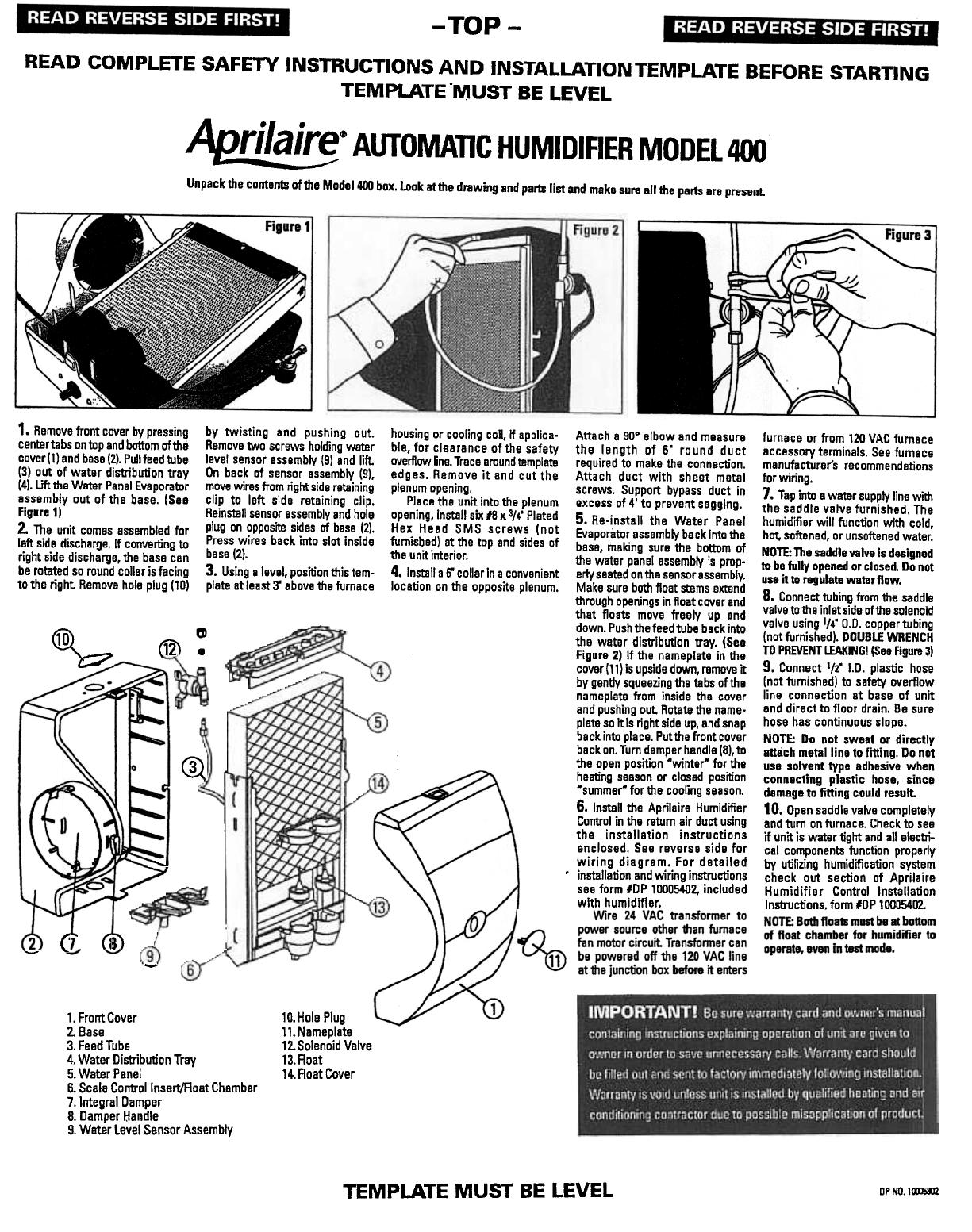
1. Remove front cover by pressing
center tabs on top and bottom of the
cover (1) and base (2). Pull feed tube
(3) out of water distribution tray
(4). Lift the Water Panel Evaporator
essembly out of the base. (See
Figure 1)
2. The unit comes assembled for
left side discharge. If converting to
right side discharge. the base can
be rotated so round collar is facing
to the right Remove hole plug (10)
by twisting and pushing out.
Remove two screws holding water
level sensor assembly (9) and lift.
On back of sensor assembly (9),
move wires from right side retaining
clip to left side retaining clip.
Reinstan sensor assembly and hole
plug on opposite sides of base (2).
Press wires back into slot inside
bese (2).
3. Using a level, position this tem-
plate at least 3' above the furnace
c
(1i).
~
@,
:
c
rID
-
~
10.Hole Plug
11.Nameplate
12. Solenoid Valve
13.Roat
14. Roat Cover
1. Front Cover
z. Base
3. Feed Tube
4. Water Distribution Tray
5. Water Pane!
6. Scal~ Controllnsert/Aoat Chember
7. Integral Damper
8. Damper Handle
9. Water Level Sensor Assembly
TEMPLATE MUST BE LEVEL
DP ND. ICXIJ5SIl
housing or cooling coil, if applica-
ble, for clearance of the safety
overflow 6ne. Trace around template
edges. Remove it and cut the
plenum opening.
Place the unit into the plenum
opening, install six #8 x 3/4' Plated
Hex Head SMS screws (not
furnished) at the top and sides of
the unit interior.
4, Install a 6' collar in a convanient
location on the opposite plenum.
Attach a SOo elbow and measure
the length of 6' round duct
required to make the connection.
Attach duct with sheet metal
screws. Support bypass duct in
excess of 4' to prevent sagging.
5, Re-install the Water Pane!
Evaporator assembly back into the
basa, making sure the bottom of
the water panel assembly is prop-
erly seated on the sensor assembly.
Make sure both float stems extend
through openings in float cover and
that floats move freely up and
down. Push the feed tube back into
the water distribution tray. (See
Figure 2) If the nameplate in the
cover!11) is upside down, remove it
by gently squeezing the tabs of the
nameplate from inside the cover
and pushing out Rotate the name-
plate so it is right side up, and snap
beck into place. Puttha front cover
back on. Tum damper hendle (8). to
the open position 'winter' for the
heating season or closed position
'summer' for the cooling seeson.
6. Install the Aprilaira Humidifier
Control in the retum air duct using
the installetion instructions
enclosed. See reverse side for
wiring diagram. For detailed
installetion and wiring instructions
see form #UP 10005402, included
with humidifier.
furnace or from 120 VAC furnace
accessory terminals. See furnace
manufacturer's recommendations
for wiring.
7, Tap into a water supply line with
the saddle valve furnished. The
humidifier will function with cold,
hot. softened, or unsoftened water.
NOTE: The saddle valve is designed
to be fully opened or closed. Do not
use it to regulate water flow.
8. Connect tubing from the saddle
valve to tile inlet side of tile solenoid
valve using 114' 0.0. coppertubing
(not furnished). DOUBLE WRENCH
TO PREVENT LEAKING! (See Figure 3)
9. Connect 1/2' I.D. plastic hose
(not furnished) to safety overflow
line connection at base of unit
and direct to floor drain. Be sure
hose has continuous slope.
NOTE: Do not sweat or directly
attach metal line to frtting. Do not
use solvent type adhesive whl~n
connecting plastic hose. sinl:e
damage to fitting could result.
10, Open saddle valve completely
and turn on furnace. Check to see
if unit is water tight and all electri-
cal components function properly
by utifizing humidification system
check out section of Aprilaire
Humidifier Control Installation
Instructions. form lOP 10005402.


 AutoFlo 250G Le manuel du propriétaire