Jenn-Air JXI5042WS0 Le manuel du propriétaire
- Catégorie
- Hottes
- Taper
- Le manuel du propriétaire
Ce manuel convient également à

JENN-AIR_36"AND 42"(91.4CM, AND 106.7CM)
HOOD
HOTTEDECUISINIEREJENN-AIR_EN|LOT
DE36"ET42"(91,4CM ET106,7CM)
InstallationInstructionsand Use&Care Guide
For questions about features, operation/performance, parts, accessories, or service in the U.S.A., call:
1-800-JENNAIR (1-800-536-6247) or visit our website at www.jennair.com.
In Canada, call: 1-800-807-6777, or visit our website at www.jennair.ca.
Instructionsd'installation etGuide d'utilisationetd'entretien
Au Canada, pour assistance, installation ou service, composez le 1-800-807-6777 ou visitez notre site web & www.jennair.ca.
Table of Contents/Table des matieres ................................... 2
IMPORTANT: READ AND SAVE THESE INSTRUCTIONS.
FOR RESIDENTIAL USE ONLY.
IMPORTANT : LIRE ET CONSERVER CES INSTRUCTIONS.
POUR UTILISATION Ri_SIDENTIELLE UNIQUEMENT.
JENN-AIR°
LI3U2A/W10274308E

TABLEOF CONTENTS
RANGE HOOD SAFETY ................................................................. 2
INSTALLATION REQUIREMENTS ................................................ 3
Tools and Parts ............................................................................ 3
Location Requirements ................................................................ 4
Venting Requirements .................................................................. 5
Electrical Requirements ............................................................... 6
INSTALLATION INSTRUCTIONS .................................................. 6
Prepare Location.......................................................................... 6
Install Range Hood ....................................................................... 7
Make Electrical Connection ......................................................... 8
Install Duct Covers ....................................................................... 8
Install Filters.................................................................................. 9
Complete Installation ................................................................... 9
RANGE HOOD USE ........................................................................ 9
Display .......................................................................................... 9
Light............................................................................................ 10
Timer........................................................................................... 10
Fan Speed Buttons .................................................................... 10
RANGE HOOD CARE ................................................................... 10
Cleaning ...................................................................................... 10
WIRING DIAGRAM ...................................................................... 12
ASSISTANCE OR SERVICE ......................................................... 13
In the U.S.A................................................................................ 13
In Canada ................................................................................... 13
Accessories ................................................................................ 13
WAR RANTY .................................................................................. 14
TABLEDESMATIERES
SECURITE DE LA HOTTE DE CUlSINIERE ............................... 15
EXIGENCES D'INSTALLATION ................................................... 17
Outils et pieces ........................................................................... 17
Exigences d'emplacement ......................................................... 17
Exigences concernant I'evacuation ........................................... 18
Specifications electriques .......................................................... 19
INSTRUCTIONS D'INSTALLATION ............................................. 20
Preparation de I'emplacement ................................................... 20
Installation de la hotte ................................................................ 20
Raccordement electrique ........................................................... 22
Installation des cache-conduits ................................................. 22
Installation des filtres.................................................................. 23
Achever I'installation.................................................................. 23
UTILISATION DE LA HOTTE ....................................................... 23
Afficheur ..................................................................................... 23
Eclairage ..................................................................................... 24
Minuterie ..................................................................................... 24
Boutons de vitesse du ventilateur.............................................. 24
ENTRETIEN DE LA HO'I-rE DE CUlSINIF:RE ............................. 25
Nettoyage ................................................................................... 25
SCHEMA DE CABLAGE .............................................................. 26
ASSISTANCE OU SERVICE ......................................................... 27
Accessoires ................................................................................ 27
GARANTIE ..................................................................................... 28
RANGE HOOD SAFETY
Your safety and the safety of others are very important.
We have provided many important safety messages in this manual and on your appliance. Always read and obey all safety
messages.
This is the safety alert symbol.
This symbol alerts you to potential hazards that can kill or hurt you and others.
All safety messages will follow the safety alert symbol and either the word "DANGER" or "WARNING."
These words mean:
You can be killed or seriously injured if you don't immediately
follow instructions.
You can be killed or seriously injured if you don't follow
instructions.
All safety messages willtell you what the potential hazard is, tell you how to reduce the chance of injury, and tell you what can
happen if the instructions are not followed.
2

iMPORTANT SAFETY iNSTRUCTiONS
WARNING: TO REDUCE THE RISK OF FIRE, ELECTRIC
SHOCK, OR INJURY TO PERSONS, OBSERVE THE
FOLLOWING:
• Use this unit only in the manner intended by the
manufacturer. If you have questions, contact the
manufacturer.
• Before servicing or cleaning the unit, switch power off at
service panel and lock the service disconnecting means to
prevent power from being switched on accidentally. When
the service disconnecting means cannot be locked,
securely fasten a prominent warning device, such as a tag,
to the service panel.
• Installation work and electrical wiring must be done by
qualified person(s) in accordance with all applicable codes
and standards, including fire-rated construction.
• Do not operate any fan with a damaged cord or plug.
Discard fan or return to an authorized service facility for
examination and/or repair.
• Sufficient air is needed for proper combustion and
exhausting of gases through the flue (chimney) of fuel
burning equipment to prevent backdrafting. Follow the
heating equipment manufacturer's guideline and safety
standards such as those published by the National Fire
Protection Association (NFPA), the American Society for
Heating, Refrigeration and Air Conditioning Engineers
(ASHRAE), and the local code authorities.
• When cutting or drilling into wall or ceiling; do not damage
electrical wiring and other utilities.
• Ducted fans must always be vented outdoors.
CAUTION: For general ventilating use only. Do not use
to exhaust hazardous or explosive materials and vapors.
CAUTION: To reduce risk of fire and to properly exhaust
air, be sure to duct air outside - do not vent exhaust air into
spaces within walls or ceilings, attics or into crawl spaces,
or garages.
WARNING: TO REDUCE THE RISK OF FIRE, USE ONLY
METAL DUCTWORK.
WARNING: TO REDUCE THE RISK OF A RANGE TOP
GREASE FIRE:
[] Never leave surface units unattended at high settings.
Boilovers cause smoking and greasy spillovers that may
ignite. Heat oils slowly on low or medium settings.
[] Always turn hood ON when cooking at high heat or when
flambeing food (i.e. Crepes Suzette, Cherries Jubilee,
Peppercorn Beef Flamb6).
[] Clean ventilating fans frequently. Grease should not be
allowed to accumulate on fan or filter.
[] Use proper pan size. Always use cookware appropriate for
the size of the surface element.
WARNING: TO REDUCE THE RISK OF INJURY TO
PERSONS IN THE EVENT OF A RANGE TOP GREASE
FIRE, OBSERVE THE FOLLOWING: a
[] SMOTHER FLAMES with a close fitting lid, cookie sheet, or
metal tray, then turn off the burner. BE CAREFUL TO
PREVENT BURNS. If the flames do not go out
immediately, EVACUATE AND CALL THE FIRE
DEPARTMENT.
[] NEVER PICK UP A FLAMING PAN - you may be burned.
[] DO NOT USE WATER, including wet dishcloths or towels -
a violent steam explosion will result.
[] Use an extinguisher ONLY if:
- You know you have a class ABC extinguisher, and you
already know how to operate it.
- The fire is small and contained in the area where it
started.
- The fire department is being called.
- You can fight the fire with your back to an exit.
aBased on "Kitchen Fire Safety Tips" published by NFPA.
[] WARNING: To reduce the risk of fire or electrical shock,
do not use this fan with any solid-state speed control
device.
READ AND SAVE THESE INSTRUCTIONS
INSTALLATIONREQUIREMENTS
Gather the required tools and parts before starting installation.
Read and follow the instructions provided with any tools listed
here.
Tools needed
• Level
• Drill with 11¼"(3.0 cm), %" (9.5 mm), %4" (2.75 mm) and
V8"(3.0 mm) drill bits
• Caulking gun and weatherproof caulking compound
• Vent clamps
• Jigsaw or keyhole saw
• Flat-blade screwdriver
• Metal snips
• Phillips screwdriver
• Pilot hole drill bits (determined by chimney support
attachment method)
• Pencil
• Wire stripper or utility knife
• Tape measure or ruler
Parts needed
• Home power supply cable
• 2 - 1/2"(12.7 mm) UL listed or CSA approved strain reliefs
• 3 UL listed wire connectors
• Pliers

For vented installations, you will also need:
• 1 wall or roof cap
• Metal vent system
For non-vented (recirculating) installations, you will also
need:
• Recirculation Kit Part Number W10272065 for non-vented
(recirculating) installations only. See "Assistance or Service"
section to order.
Parts supplied
Remove parts from packages. Check that all parts are included.
• Hood canopy assembly with ventilator and light bulbs
installed
• 8 vertical supports
• 2 glass mounting brackets
• Glass mantle
• Mounting template
• Upper horizontal support
• Horizontal support
• 4 plastic brackets (for lower chimney fixings)
• 2 plastic brackets (for upper chimney fixings)
• 68-4x8mmscrews
• 4 - 3.5 x 9.5 mm glass mantle mounting screws
• 4-5x45mmscrews
IMPORTANT: Observe all governing codes and ordinances.
Have a qualified technician install the range hood. It is the
installer's responsibility to comply with installation clearances
specified on the model/serial rating plate. The model/serial rating
plate is located behind the left filter on the rear wall of the vent
hood.
Canopy hood location should be away from strong draft areas,
such as windows, doors and strong heating vents.
Cabinet opening dimensions that are shown must be used. Given
dimensions provide minimum clearance.
Grounded electrical outlet is required. See "Electrical
Requirements" section.
Because of the size and weight of this island hood, the chimney
support must be securely attached to the ceiling.
• For plaster or drywall ceilings, the chimney support must be
attached to joists. If this is not possible, you must build a
support structure behind the plaster or drywall. The support
structure must be able to support 80 Ibs (36.6 kg).
The range hood is factory set for venting through the roof or wall.
For non-vented (recirculating) Installation see "Non-vented
(recirculating) Installations" in "Install Range Hood" section.
Recirculation Kit Part Number W10272065 is available from your
dealer or an authorized parts distributor.
All openings in ceiling and wall where range hood will be installed
must be sealed.
For Mobile Home Installations
The installation of this range hood must conform to the
Manufactured Home Construction Safety Standards, Title 24
CFR, Part 328 (formerly the Federal Standard for Mobile Home
Construction and Safety, Title 24, HUD, Part 280) or when such
standard is not applicable, the standard for Manufactured Home
Installation 1982 (Manufactured Home Sites, Communities and
Setups) ANSI A225.1/NFPA 501A, or latest edition, or with local
codes.
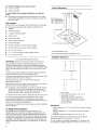
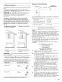
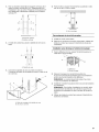
Product Dimensions
133/8" 15" (38.0 Ore)
25W' (64.0 crn)
_t_ (4.0crn)
36" - 42" (91.4 om to 106.7 ore)
*Vented installations only
**Non-vented (recirculating) installations only
Installation Clearances
1
B*
1
C
1
A. Ceiling height
B. Hood height from ceifing to bottom of the
range hood: A-C-D=B
C. Hood height: 24" (61.0 cm) min. from
electric cooking surface, 30" (76.2 cm)
min. from gas cooking surface, suggested
36" (91.4 cm) max
D. Countertop height
IM PORTANT:
Minimum distance "C": 24" (61.0 cm) from electric cooking
surface.
Minimum distance "C": 27" (68.6 cm) from gas cooking
surfaces.
Suggested maximum distance "C": 36" (91.4 cm)
For vented installations, the chimneys can be adjusted for
ceilings between 8' (2.4 m) and 9' 11" (3.0 m).
For non-vented (recirculating) installations, the chimneys can
be adjusted for ceilings between 8' (2.4 m) and 10' 4" (3.1 m).

*NOTE:Therangehoodchimneysareadjustableanddesigned
tomeetvaryingceilingorsoffitheightsdependingonthe
distance"C"betweenthebottomoftherangehoodandthe
cookingsurface.Forhigherceilings,aStainlessSteelChimney
ExtensionKitPartNumberW10272072isavailablefromyour
dealeroranauthorizedpartsdistributor.Thechimneyextension
replacestheupperchimneyshippedwiththerangehood.
(ve_"_ed modes @_y}
Vent system must terminate to the outdoors, except for non-
vented (recirculating) installations.
Do not terminate the vent system in an attic or other enclosed
area.
• Do not use 4" (10.2 cm) laundry-type wall cap.
• Use metal vent only. Rigid metal vent is recommended.
Plastic or metal foil vent is not recommended.
• The length of vent system and number of elbows should be
kept to a minimum to provide efficient performance.
For the most efficient and quiet operation:
• Use no more than three 90° elbows.
• Make sure there is a minimum of 24" (61.0 cm) of straight
vent between the elbows if more than 1 elbow is used.
• Do not install 2 elbows together.
• Use clamps to seal all joints in the vent system.
• Use caulking to seal exterior wall or roof opening around the
cap.
• The size of the vent should be uniform.
Cold Weather Installations
An additional back draft damper should be installed to minimize
backward cold air flow and a thermal break should be installed to
minimize conduction of outside temperatures as part of the vent
system. The damper should be on the cold air side of the thermal
break.
The break should be as close as possible to where the vent
system enters the heated portion of the house.
Makeup Air
Local building codes may require the use of makeup air systems
when using ventilation systems greater than specified CFM of air
movement. The specified CFM varies from locale to locale.
Consult your HVAC professional for specific requirements in your
area.
Venting Methods
This range hood is factory set for venting through the roof.
A 8" (20.3 cm) round vent system is needed for installation (not
included). The hood exhaust opening is 8" (20.3 cm) round.
NOTE: Flexible vent is not recommended. Flexible vent creates
back pressure and air turbulence that greatly reduce
performance.
For Non-Vented (recirculating) Installations
If it is not possible to vent cooking fumes and vapors to the
outside, the hood can be used in the non-vented (recirculating)
version, using a Recirculation Kit (which includes charcoal filters
and a deflector). To order, see the "Assistance or Service"
section.
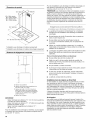
Non-vented (recirculating) Roof Venting
A. Deflector
B. 8" (20.3 cm) round vent
A. Roof cap
B. 8" (20.3 cm) round vent
NOTE: Wall venting can be an option for 2-story homes.
Calculating Vent System Length
To calculate the length of the system you need, add the
equivalent feet (meters) for each vent piece used in the system.
Vent piece 8" (20.3 cm) round
45° elbow 2.5 ft
(0.8 m)
90° elbow 5.0 ft
(1.5m)
Maximum equivalent vent length is 35 ft (10.7 m).
Example vent system
90° e, bow I .......W aHcap
The following example falls within the maximum recommended
vent length of 35 ft (10.7 m).
1 - 90° elbow = 5.0 ft (1.5 m)
1 - wall cap = 0.0 ft (0.0 m)
8 ft (2.4 m) straight = 8.0 ft (2.4 m)
Length of system = 13.0 ft (3.9 m)

Observeallgoverningcodesandordinances.
Ensurethattheelectricalinstallationisadequateandin
conformancewithNationalElectricalCode,ANSI/NFPA70(latest
edition),orCSAStandardsC22.1-94,CanadianElectricalCode,
Part1andC22.2No.0-M91(latestedition)andalllocalcodes
andordinances.
Ifcodespermitandaseparategroundwireisused,itis
recommendedthataqualifiedelectriciandeterminethatthe
groundpathisadequate.
Acopyoftheabovecodestandardscanbeobtainedfrom:
NationalFireProtectionAssociation
OneBatterymarchPark
Quincy,MA02269
CSAInternational
8501EastPleasantValleyRoad
Cleveland,OH44131-5575
• A 120 Volt, 60 Hz., AC only, 15-amp, fused electrical circuit is
required.
If the house has aluminum wiring, follow the procedure
below:
1. Connect a section of solid copper wire to the pigtail
leads.
2. Connect the aluminum wiring to the added section of
copper wire using special connectors and/or tools
designed and UL listed for joining copper to aluminum.
Follow the electrical connector manufacturer's recommended
procedure. Aluminum/copper connection must conform with
local codes and industry accepted wiring practices.
Wire sizes and connections must conform with the rating of
the appliance as specified on the model/serial rating plate.
The model/serial plate is located behind the filter on the rear
wall of the range hood.
Wire sizes must conform to the requirements of the National
Electrical Code, ANSI/NFPA 70 (latest edition), or CSA
Standards C22.1-94, Canadian Electrical Code, Part 1 and
C22.2 No. 0-M91 (latest edition) and all local codes and
ordinances.
INSTALLATIONINSTRUCTIONS
• It is recommended that the vent system be installed before 6. Tape template in place on the ceiling at the marked
the range hood is installed, centerline.
Before making cutouts, make sure there is proper clearance
within the ceiling for exhaust vent.
Range hood is to be installed 24" (61.0 cm) min. for electric
cooking surfaces, 27" (68.6 cm) min. for gas cooking surfaces,
to a suggested maximum of 36" (91.4 cm) above the cooking
surface.
• Check your ceiling height and the range hood height
maximum before you select your hood.
1. Disconnect power.
2. Determine which venting method to use: roof, wall or non-
vented.
7,
Use a pencil to mark the mounting screws, wire access and
duct hole locations on the ceiling.
NOTE: Mounting hole locations should be into the ceiling
support structure.
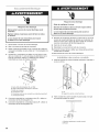
3. Select a flat surface for assembling the range hood. Place
covering over that surface.
Excessive Weight Hazard
Use two or more people to move and install
range hood.
Failure to do so can result in back or other injury.
8.
9.
10.
Remove the template.
Drill 4 - 3Ae"(4.8 mm) pilot holes for mounting the upper
horizontal support.
Determine the required location for the home power supply
cable and drill a 1/2"(1.3 cm) diameter hole for wire access.
Run wire through the home power supply cable according to
the National Electrical Code or CSA Standards and local
codes and ordinances. There must be enough 1/2"conduit
and wires from the fused disconnect (or circuit breaker) box
to make the connection in the hood's electrical terminal box.
NOTE: Do not reconnect power until installation is complete.
4,
5.
Using 2 or more people, lift range hood onto covered surface.
Determine and mark the centerline on the ceiling where the
range hood will be installed, considering the requirements for
ceiling support structures. See the "Location Requirements"
section. Make sure the range hood is centered over the
cooking surface.
Use caulk to seal all openings.
11. (For vented installations only.) Using a jigsaw or keyhole saw,
cut a 81/2"(21.6 cm) diameter hole for the vent duct.
6

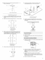
12. Attach the upper horizontal support bracket with 4 - 5 x 5. Connect glass mantle to range hood with the 2 glass
45 mm wood screws, mounting brackets and 4 - 3.5 x 9.5 mm screws.
A
A. Upper horizontal support
1. Position the 4 vertical supports (A) with the notches at the
bottom and attach to the range hood using 16 - 4 x 8 mm
screws.
2. Attach the horizontal support (B) using 8 - 4 x 8 mm screws.
3=
A
_m..............
C ..................................................
[
A. Vertical supports
B. Horizontal support
C. Notched end
Attach a second set of vertical supports (A) and set the
vertical height (B). See "Installation Clearances" in the
"Location Requirements" section to help determine the
desired dimension for vertical height "B."
A
I I
A. Verticalsuppoarts
B. Verticalheight
B
4. Using 2 people, place the glass mantle onto the range hood.
A. Glass mantle
B A
I
i
6=
A. Glass mounting bracket
B. 3.5 x 9.5 mm screws
Attach the range hood assembly to the upper horizontal
support attached to the ceiling using 16 - 4 x 8 mm screws
and tighten.
iiiiiiiiiiiiiiiiiiiiiiiiiiiiiiiiiiiiiiiiiiiiiiiiiiiiiiiiiiiiiiiiiiiiiiiiiiiiiiiiiiiiiiiiiiiiiiiiiiiiiiiiiiiiiiiiiiiiiiiiiiiiiiiiiiiiiiiiiiiiiiiiiiiiiiiiiiiiiiiiiiiiiiiiiiiiiiiiiiiiiiiiiiiiiiiiiiiiiiiiiiiiiiiiiiiiiiiiiiiiiiiiiiiiiiiiiiiiiiiiiiiiiiiiiiiiiiiiiiiiiiiiiiiiiiiiiiiiiiiiiiiiiiiiiiiiiiiiiiiiiiiiiiiiiiiiiiiiiiiiiiiiiiiiiiiiiiiiiiiiiiiiiiiiiiiiiiiiiiiiiiiiiiiiiiiiiiiiiiiiiiiiiiiiiiiiiiiiiiiiiiiiiiiiiiiiiiiiiiiiiiiiiiii i1i!i!!ii
! !
A.Mounting screws
Connect Vent System
1. Install vent system.
2. Push duct over the exhaust outlet. Seal all connections with
vent clamps.
Non-Vented (recirculating) Installation
1. Attach the air deflector to the upper horizontal support using
4 mounting screws.
2=
A. Deflector
B. Mounting screws
Measure the length of 8" (20.3 cm) duct (not included)
needed to connect the transition to the deflector.
NOTE: Vent should fit up inside the deflector 1" (2.5 cm)
minimum.
3. Install vent between the transition and the deflector.
NOTE: To make vent installation easier, temporarily remove
the deflector from the chimney support bracket and replace
after vent section is in place.
4. Seal all connections with vent clamps.

1=
2.
3.
4=
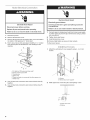
Electrical Shock Hazard
Disconnect power before servicing.
Replace all parts and panels before operating.
Failure to do so can result in death or electrical shock.
Disconnect power.
Remove terminal box cover.
Remove the knockout in the terminal box cover and install a
UL listed or CSA approved 1/2"strain relief.
Run 3 wires, black, white and green (14AWG), in 1/2"conduit
from service panel to terminal box. Use caulking to seal
opening.
g ......................................F _
D
E c
A. UL listed or CSA approved strain refief
B. Home power supply cable
C. Terminal box
D. Black wires
E. Green (or bare) wire connected to yellow-green wire
F. White wires
5. Use UL listed wire connectors and connect black wires (D)
together.
6. Use UL listed wire connectors and connect white wires (F)
together.
Electrical Shock Hazard
Electrically ground blower.
Connect ground wire to green and yellow ground wire
in terminal box.
Failure to do so can result in death or electrical shock.
7. Connect green (or bare) ground wire from home power supply
to yellow-green ground wire (E)in terminal box using UL listed
wire connectors.
8. Tighten strain relief screw.
9. Install terminal box cover.
10. Check all light bulbs are secure in their sockets.
11. Reconnect power.
1. Attach the vertical duct cover supports using 4 - 4 x 8 mm
screws.
B
A. Screws
B. Vertical duct cover support
2. Slide upper duct covers into place until springs "click."
A. Upper duct cover
B. Spring
8

3. Attach lower duct covers using a plastic bracket at each
corner (4 needed).
A. Upper duct cover
B. Lower duct cover
C. Plastic bracket
For non-vented (recirculating installations):
1. Install optional charcoal filter, wrapping it around the grease
filter.
2. Place the charcoal filter mat around the grease filter and fix it
in place by using the cap lock springs provided.
3=
Position the upper cap and fix it in place using the cap lock
spring provided.
B
C
A. Charcoal filter mat
B. Grease filter
C. Charcoal filter side
lock springs
D. Upper cap
E. Cap lock spring
F. Grease filter support
For all installations:
4. Install the grease filter. See "Range Hood Care" section.
Check Range Hood Operation
If range hood does not operate, check to see whether a circuit
breaker has tripped or a household fuse has blown.
NOTE: To get the most efficient use from your new range hood,
read the "Range Hood Use" section.
RANGE HOOD USE
The range hood is designed to remove smoke, cooking vapors
and odors from the cooktop area. For best results, start the hood
before cooking and allow it to operate several minutes after the
cooking is complete to clear all smoke and odors from the
kitchen.
Control Panel
The range hood controls are located on the front side of the
canopy.
A B C D E
Ir I
=. o............7,o,88-88
A. Power decrease D. Light
B. Power increase E. Timer
C. Display
Charcoal Filter Saturation Alarm
After 120 hours of fan function, the display will show "Replace
Charcoal Filter" when the fan is active. When this icon shows in
the display, the charcoal filters should be replaced. See "Range
Hood Care" section.
• To reset the charcoal filter saturation alarm, press and hold
the POWER DECREASE button for 5 seconds. The "Replace
Charcoal Filter" icon will no longer be displayed.
Audible Signal Activation and Deactivation
The audible signals can be activated or deactivated by pressing
the "LIGHT" button for 5 seconds.
• If the audible signal is activated, a tone will sound, and "Snd"
will appear on the display for 3 seconds.
• If the audible signal is deactivated, "Snd" will appear on the
display for 3 seconds.
Grease Filter Saturation Alarm
After 30 hours of fan function, the display will show "Clean
Grease Filter" when the fan is active. When this icon shows in the
display, the installed grease filters should be washed. See
"Range Hood Care" section.
• To reset the grease filter saturation alarm, press and hold the
POWER INCREASE button for 5 seconds. The "Clean Grease
Filter" icon will no longer be displayed.
Charcoal Filter (Recirculation Accessory) Inclusion and
Exclusion
When the charcoal filter is in use (recirculating mode), press and
hold the POWER DECREASE and POWER INCREASE buttons at
the same time for 5 seconds. "Able" will appear on the display for
3 seconds.
If the charcoal filter is not used (vented mode), press and hold
the POWER DECREASE and POWER INCREASE buttons at the
same time for 5 seconds. "None" will appear on the display for
3 seconds.

• Whenthecharcoalfilterhasbeenexcluded,thecharcoalfilter
alarmisdisabled.
• Theinclusionorexclusionofthecharcoalfiltermustbe
selectedwhilethelightsandthefanmotorareOff.
Heat Sensor
The control is equipped with a heat sensor that will turn on the
blower to the highest speed if excessive heat occurs around the
control area.
• If the blower is On or Off, the blower will automatically set to
the highest speed. "Auto" will appear in the display to
indicate that the heat sensor has detected excessive heat.
• When the blower is operating due to excessive heat detected
by the heat sensor, the blower speed cannot be decreased.
• When the temperature level on the hood drops to normal, the
blower will return to its setting before the excessive heat was
sensed.
To operate the light:
1. Press the Light button to turn the light on to high.
2. Press the Light button again to turn the light to low.
3. Press the Light button a third time to turn the light off.
The timer can be set from 1 to 60 minutes. The default timer
setting is 10 minutes.
To use the timer:
1. Press the Timer button to enter the timer mode. After
5 seconds the default time will be automatically selected.
2. Press the POWER DECREASE and POWER INCREASE
buttons while the display is flashing (5 seconds) to adjust to
the desired time. Pressing the timer button again or waiting
5 seconds after selecting the desired time will start the timer
countdown.
3. The timer can be canceled at any time by pressing the Timer
button again.
NOTE: During the timer setup, the Power Decrease and Power
Increase buttons are dedicated to the timer. After the timer starts,
the Power Decrease and Power Increase buttons can be used for
other functions.
Power Increase/On
This button is used to turn the fan On or increase the fan speed.
• The fan will turn On if the Power Increase button is pressed
and the hood was Off.
• An audible tone will sound when the fan reaches its highest
speed.
Power Decrease/Off
• This button is used to turn the fan Off or to decrease the fan
speed.
RANGE HOOD CARE
IMPORTANT: Clean the hood and grease filters frequently
according to the following instructions. Replace grease filters
before operating hood.
Be sure lights are cool before cleaning the hood.
To Remove Metal Grease Filters
1. Turn off fan and lights. Check that halogen lamp is cool.
2. Remove the filter holder frame and grease filter using a flat-
blade screwdriver to turn the grease filter release screws 90°
counterclockwise.
Exterior Surfaces
Clean the range hood with a mild detergent and soft cloth. To
avoid damage to the exterior surface, do not use abrasive
cleanser or steel-wool pads.
Metal Grease Filters
The filters should be washed frequently. Place metal filters in
dishwasher or hot detergent solution to clean.
Let filter dry thoroughly before replacing it.
...................................................................................S
A
A. Grease filter release screw
B. Filter holder frame
C. Grease filter
10

To Replace Metal Grease Filter
1. Turn off fan and lights. Check that halogen lamp is cool.
2. Remove the filter holder frame and grease filter using a flat-
blade screwdriver to turn the grease filter release screws 90°
counterclockwise.
3. Replace grease filter and filter holder frame into range hood.
Align the grease filter release screw and use a flat-blade
screwdriver to turn the grease filter release screws 90°
clockwise to lock in place.
Charcoal Filters - For Non-Vented (recirculating)
Installations
NOTE: After approximately 3 years of use the charcoal filter
should be replaced. To order a replacement Charcoal Filter Kit,
see the "Assistance or Service" section.
The charcoal filters can be cleaned and reactivated. Clean the
filter in the dishwasher using normal detergent and choosing the
highest temperature setting.
To reactivate the filter, the filter should be dried in an oven for
10 minutes with a maximum temperature of 210°F (100°C).
To Replace Charcoal Filters
1. Turn fan and lights off. Check that halogen lamp is cool.
2. Remove the metal grease filters. See "Metal Grease Filters"
section.
3. Remove the upper and side lock springs.
4. Clean or discard the charcoal filter.
5. Install cleaned or replacement filter.
Replacing a Halogen Lamp
Turn off the range hood and allow the halogen lamp to cool. To
avoid damage or decreasing the life of the new bulb, do not
touch bulb with bare fingers. Replace bulb, using tissue or
wearing cotton gloves to handle bulb.
If new lights do not operate, make sure the lamps are inserted
correctly before calling service.
1. Disconnect power.
2. Use a flat-blade screwdriver and gently pry the light cover
loose.
3. Remove the lamp and replace with a 12-volt, 20-watt
maximum, halogen lamp made for a G-4 base.
4. Replace the light cover.
5. Reconnect power.
11

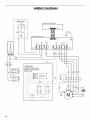
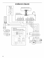
WIRING DIAGRAM
Wiringbox
L@N
I
R
BR
ElectronicUserInterface
ElectronicPowerBoard
N L NL NM
P1 P2 P4A P3 P4
R
ATTENTION:
Additionallamps only
present ontheversions
with 4 lamps
BR
CON2 1
Y-G
-L1
CON1
LA
P5
14
>-
$3 $2 $1
P8 P7 P6
cc _
Q_ rn c_
'I, dh r
O3
12

ASSISTANCEOR SERVICE
When calling for assistance or service, please know the purchase
date and the complete model and serial number of your
appliance. This information will help us to better respond to your
request.
If you need replacement parts
If you need to order replacement parts, we recommend that you
use only factory specified parts. Factory specified parts will fit
right and work right because they are made with the same
precision used to build every new appliance. To locate factory
specified replacement parts in your area, call us or your nearest
designated service center.
Call the dealer from whom your appliance was purchased, or call
1-800-JENNAIR (1-800-536-6247) to locate an authorized
service company. When calling, please know the purchase date
and the complete model and serial number of your appliance. Be
sure to retain proof of purchase to verify warranty status.
If the dealer or service company cannot resolve your problem,
write to:
Jenn-Air Brand Home Appliances
Customer eXperience Center
553 Benson Road
Benton Harbor, MI 49022-2692
Web address: www.jennair.com
Or call: 1-800-536-6247
U.S. customers using -I-I-Yfor deaf, hearing impaired or speech
impaired, call: 1-800-688-2080 (Monday - Friday, 8:00 a.m. -
8:00 p.m. Eastern Time).
NOTE: When writing or calling about a service problem, please
include the following information:
1. Your name, address and daytime telephone number.
2. Appliance model number and serial number.
3. Name and address of your dealer or servicer.
4. A clear description of the problem you are having.
5. Proof of purchase (sales receipt).
User's guides, service manuals and parts information are
available from Jenn-Air Brand Home Appliances, Customer
eXperience Center.
Call the dealer from whom your appliance was purchased, or call
Jenn-Air at 1-800-807-6777 to locate an authorized service
company. When calling, please know the purchase date and the
complete model and serial number of your appliance. Be sure to
retain proof of purchase to verify warranty status.
If the dealer or service company cannot resolve your problem,
write to:
Jenn-Air Brand Home Appliances
Customer eXperience Centre
1901 Minnesota Court
Mississauga, ON L5N 3A7
Web address: www.jennair.ca
Or call: 1-800-807-6777.
NOTE: When writing or calling about a service problem, please
include the following information:
1. Your name, address and daytime telephone number.
2. Appliance model number and serial number.
3. Name and address of your dealer or servicer.
4. A clear description of the problem you are having.
5. Proof of purchase (sales receipt).
User's guides, service manuals and parts information are
available from Jenn-Air Brand Home Appliances, Customer
eXperience Centre.
Replacement Charcoal Filter
(for non-vented installations only)
Order Part Number W10272069
Recirculation Kit
(for non-vented installations only)
Order Part Number W10272065
Chimney Extension Kit
Order Part Number W10272072
13

JENN-AIR MAJOR APPLIANCEWARRANTY
ONE YEAR LIMITED WARRANTY
For one year from the date of purchase, when this major appliance is operated and maintained according to instructions attached to or
furnished with the product, Jenn-Air brand of Whirlpool Corporation or Whirlpool Canada LP (hereafter "Jenn-Air") will pay for factory
specified parts and repair labor to correct defects in materials or workmanship. Service must be provided by a Jenn-Air designated
service company. This limited warranty is valid only in the United States or Canada and applies only when the major appliance is used
in the country in which it was purchased. Outside the 50 United States and Canada, this limited warranty does not apply. Proof of
original purchase date is required to obtain service under this limited warranty.
ITEMS EXCLUDED FROM WARRANTY
This limited warranty does not cover:
1. Service calls to correct the installation of your major appliance, to instruct you on how to use your major appliance, to replace or
repair house fuses, or to correct house wiring or plumbing.
2. Service calls to repair or replace appliance light bulbs, air filters or water filters. Consumable parts are excluded from warranty
coverage.
3. Repairs when your major appliance is used for other than normal, single-family household use or when it is used in a manner that is
contrary to published user or operator instructions and/or installation instructions.
4. Damage resulting from accident, alteration, misuse, abuse, fire, flood, acts of God, improper installation, installation not in
accordance with electrical or plumbing codes, or use of consumables or cleaning products not approved by Jenn-Air.
5. Cosmetic damage, including scratches, dents, chips or other damage to the finish of your major appliance, unless such damage
results from defects in materials or workmanship and is reported to Jenn-Air within 30 days from the date of purchase.
6. Any food loss due to refrigerator or freezer product failures.
7. Costs associated with the removal from your home of your major appliance for repairs. This major appliance is designed to be
repaired in the home and only in-home service is covered by this warranty.
8. Repairs to parts or systems resulting from unauthorized modifications made to the appliance.
9. Expenses for travel and transportation for product service if your major appliance is located in a remote area where service by an
authorized Jenn-Air servicer is not available.
10. The removal and reinstallation of your major appliance if it is installed in an inaccessible location or is not installed in accordance
with published installation instructions.
11. Major appliances with original model/serial numbers that have been removed, altered or cannot be easily determined. This warranty
is void if the factory applied serial number has been altered or removed from your major appliance.
The cost of repair or replacement under these excluded circumstances shall be borne by the customer.
DISCLAIMER OF IMPLIED WARRANTIES; LIMITATION OF REMEDIES
CUSTOMER'S SOLE AND EXCLUSIVE REMEDY UNDER THIS LIMITED WARRANTY SHALL BE PRODUCT REPAIR AS PROVIDED
HEREIN. IMPLIED WARRANTIES, INCLUDING WARRANTIES OF MERCHANTABILITY OR FITNESS FOR A PARTICULAR PURPOSE,
ARE LIMITED TO ONE YEAR OR THE SHORTEST PERIOD ALLOWED BY LAW. JENN-AIR SHALL NOT BE LIABLE FOR INCIDENTAL
OR CONSEQUENTIAL DAMAGES. SOME STATES AND PROVINCES DO NOT ALLOW THE EXCLUSION OR LIMITATION OF
INCIDENTAL OR CONSEQUENTIAL DAMAGES, OR LIMITATIONS ON THE DURATION OF IMPLIED WARRANTIES OF
MERCHANTABILITY OR FITNESS, SO THESE EXCLUSIONS OR LIMITATIONS MAY NOT APPLY TO YOU. THIS WARRANTY GIVES
YOU SPECIFIC LEGAL RIGHTS, AND YOU MAY ALSO HAVE OTHER RIGHTS WHICH VARY FROM STATE TO STATE OR PROVINCE
TO PROVINCE.
If outside the 50 United States and Canada, contact your authorized Jenn-Air dealer to determine if another warranty applies.
If you need service, first see the "Troubleshooting" section of the Use & Care Guide. After checking "Troubleshooting," you may find
additional help by checking the "Assistance or Service" section or by calling Jenn-Air. In the U.S.A., call 1-800-536-6247. In Canada,
call 1-800-807-6777. 6/09
Keep this book and your sales slip together for future
reference. You must provide proof of purchase or installation
date for in-warranty service.
Write down the following information about your major appliance
to better help you obtain assistance or service if you ever need it.
You will need to know your complete model number and serial
number. You can find this information on the model and serial
number label located on the product.
Dealer name
Address
Phone number
Model number
Serial number
Purchase date
14

SECURITEDELA HOTTEDECUlSlNIERE
Votre securite et celle des autres est tres importante.
Nous donnons de nombreux messages de s_curit_ importants dans ce manuel et sur votre appareil m_nager. Assurez-vous de
toujours lire tousles messages de s_curit_ et de vous y conformer.
Voici le symbole d'alerte de s_curit&
Ce symbole d'alerte de s_curit_ vous signale les dangers potentiels de d_c_s et de blessures graves & vous
et & d'autres.
Tousles messages de s_curit_ suivront le symbole d'alerte de s_curit_ et le mot "DANGER" ou
"AVERTISSEMENT". Ces mots signifient •
Risque possible de d_cbs ou de blessure grave si vous ne
suivez pas imm_diatement les instructions.
Risque possible de d_cbs ou de blessure grave si vous
ne suivez pas les instructions.
Tous les messages de s_curit_ vous diront quel est le danger potentiel et vous disent comment r_duire le risque de blessure et
ce qui peut se produire en cas de non-respect des instructions.
15

llVIPORTANTES iNSTRUCTiONS DE Sl CURITl
AVERTISSEMENT : POUR REDUIRE LE RISQUE
D'INCENDIE, CHOC ¢:LECTRIQUE OU DOMMAGES
CORPORELS, RESPECTER LES INSTRUCTIONS
SUIVANTES :
m Utiliser cet appareil uniquement dans les applications
envisag6es par le fabricant. Pour toute question, contacter
le fabricant.
m Avant d'entreprendre un travail d'entretien ou de nettoyage,
interrompre I'alimentation de la hotte au niveau du tableau
de disjoncteurs, et verrouiller le tableau de disjoncteurs
pour emp6cher tout r@ablissement accidentel de
I'alimentation du circuit. Lorsqu'il n'est pas possible de
verrouiller le tableau de disjoncteurs, placer sur le tableau
de disjoncteurs une @iquette d'avertissement pro6minente
interdisant le r@ablissement de I'alimentation.
m Tout travail d'installation ou c&blage 61ectrique doit 6tre
r6alis6 par une personne qualifi6e, dans le respect des
prescriptions de tousles codes et normes applicables, y
compris les codes du b&timent et de protection contre les
incendies.
m Ne pas faire fonctionner un ventilateur dont le cordon ou la
fiche est endommag6(e). Jeter le ventilateur ou le retourner
&un centre de service agr66 pour examen et/ou r6paration.
m Une source d'air de d6bit suffisant est n6cessaire pour le
fonctionnement correct de tout appareil a gaz (combustion
et 6vacuation des gaz & combustion par la chemin6e), pour
qu'il n'y ait pas de reflux des gaz de combustion. Respecter
les directives du fabricant de 1'6quipement de chauffage et
les prescriptions des normes de s6curit6 - comme celles
publi6es par la National Fire Protection Association (NFPA)
et I'American Society for Heating, Refrigeration and Air
Conditioning Engineers (ASHRAE), et les prescriptions des
autorit6s r6glementaires locales.
m Lors d'op@ations de d6coupage et de per£age dans un mur
ou un plafond, veiller a ne pas endommager les c&blages
61ectriques ou canalisations qui peuvent s'y trouver.
m Les ventilateurs d'6vacuation doivent toujours d6charger
I'air a I'ext@ieur.
MISE EN GARDE : Cet appareil est congu uniquement
pour la ventilation g6n@ale. Ne pas I'utiliser pour I'extraction
de mati_res ou vapeurs dangereuses ou explosives.
MISE EN GARDE : Pour minimiser le risque d'incendie
et 6vacuer ad6quatement les gaz, veiller & acheminer I'air
aspir6 par un conduit jusqu'b, I'ext@ieur - ne pas d6charger
I'air aspir6 dans un espace vide du b&timent comme une
cavit6 murale, un plafond, un grenier, un vide sanitaire ou
un garage.
AVERTISSEMENT : POUR RCDUIRE LE RISQUE
D'INCENDIE, UTILISER UNIQUEMENT DES CONDUITS
MI2TALLIQUES.
AVERTISSEMENT : POUR MINIMISER LE RISQUE
D'UN FEU DE GRAISSE SUR LA CUISINIF:RE :
[] Ne jamais laisser un 616ment de surface fonctionner &
puissance de chauffage maximale sans surveillance. Un
renversement/d6bordement de mati@e graisseuse pourrait
provoquer une inflammation et la g6n@ation de fum6e.
Utiliser une puissance de chauffage moyenne ou basse
pour le chauffage d'huile.
[] Veiller & toujours faire fonctionner le ventilateur de la hotte
Iors de la cuisson avec une puissance de chauffage 61ev6e
ou Iors de la cuisson d'un mets a flamber (& savoir cr6pes
Suzette, cerise jubil6e, steak au poivre flamb6).
[] Nettoyer fr6quemment les ventilateurs d'extraction. Veiller
ne pas laisser la graisse s'accumuler sur les surfaces du
ventilateur ou des filtres.
[] Utiliser toujours un ustensile de taille appropri6e. Utiliser
toujours un ustensile adapt6 a la taille de 1'616ment
chauffant.
AVERTISSEMENT : POUR RC:DUIRE LE RISQUE DE
DOMMAGES CORPORELS APRF:S LE DECLENCHEMENT
D'UN FEU DE GRAISSE SUR LA CUISINIF:RE, APPLIQUER
LES RECOMMANDATIONS SUIVANTES :a
[] Placer sur le r6cipient un couvercle bien ajust6, une t61e &
biscuits ou un plateau m6tallique POUR ETOUFFER LES
FLAMMES, puis 6teindre le brOleur. VEILLER ,&.¢:VITER
LES BRULURES. Si les flammes ne s'@eignent pas
imm6diatement, CVACUER LA PIECE ET APPELER LES
POMPIERS.
[] NE JAMAIS PRENDRE EN MAIN UN RECIPIENT
ENFLAMME - vous risquez de vous brQler.
[] NE PAS UTILISER D'EAU, ni un torchon humide - ceci
pourrait provoquer une explosion de vapeur brQlante.
[] Utiliser un extincteur SEULEMENT si:
- IIs'agit d'un extincteur de classe ABC, dont on connaft le
fonctionnement.
- IIs'agit d'un petit feu encore limit6 & I'endroit oQ il s'est
d6clar&
- Les pompiers ont 6t6 contact6s.
- II est possible de garder le dos orient6 vers une sortie
pendant I'op@ation de lutte contre le feu.
aRecommandations tir6es des conseils de s6curit6 en cas
d'incendie de cuisine publi6s par la NFPA.
[] AVERTISSEMENT : Pour r6duire le risque d'incendie
ou de choc 61ectrique, ne pas utiliser ce ventilateur avec un
quelconque dispositif de r6glage de la vitesse & semi-
conducteurs.
LIRE ET CONSERVER CES INSTRUCTIONS
16

EXIGENCESD'INSTALLATION
Rassembler les outils et composants nicessaires avant
d'entreprendre I'installation. Lire et observer les instructions
fournies avec chacun des outils de la liste ci-dessous.
Outils n_cessaires
• Niveau
• Perceuse avec forets de 11¼"(3 cm), 3/8"(9,5 mm),
%4" (2,75 mm) et forets de 1/8"(3 mm)
• Forets & avant-trou (selon la methode de fixation du support
de cheminee)
• Crayon
• Pince & denuder ou couteau utilitaire
• Metre-ruban ou regle
• Pince
• Pistolet & calfeutrage et compose de calfeutrage resistant
aux intemperies
• Brides de conduit
• Scie sauteuse ou scie & guichet
• Tournevis & lame plate
• Cisaille de ferblantier
• Tournevis Phillips
Pi6ces n6cessaires
• C&ble d'alimentation electrique du domicile
• 2 serre-c&ble de 1/2"(12,7 mm) (homologation UL ou CSA)
• 3 connecteurs de ills homologues UL
Pour les installations avec d_charge a I'ext_rieur, il vous
faudra aussi :
• 1 bouche de decharge (decharge a travers lemur ou & travers
le toit)
• Circuit d'evacuation metallique
Pour les installations sans d_charge a I'ext_rieur (recyclage),
il faudra aussi :
• Ensemble de recyclage, piece numero W10272065 pour une
installation sans decharge & I'exterieur (recyclage)
uniquement. Voir la section "Assistance ou service" pour
commander.
Pi6ces fournies
Retirer les pieces de leur emballage. Verifier que toutes les
pieces sont presentes.
• Auvent de hotte avec ventilateur et lampes installes
• 8 supports verticaux
• 2 supports de fixation de la tablette de verre
• Tablette de verre
• Gabarit de montage
• Support horizontal
• 4 brides de plastique (pour les attaches de section inferieure
de cheminee)
• 2 brides de plastique (pour les attaches de section superieure
de cheminee)
• 68visde4x8mm
• 4 vis de montage de 3,5 x 9,5 mm de la tablette de verre
• 4visde5x45mm
IMPORTANT : Observer les dispositions de tous les codes et
reglements en vigueur.
Oonfier I'installation de la hotte &un technicien qualifi& O'est
I'installateur qu'incombe la responsabilite de respecter les
distances de separation specifiees sur la plaque signaletique de
I'appareil. La plaque signaletique de I'appareil est situee derriere
le filtre de gauche, sur la paroi arriere de la hotte.
On doit toujours installer la hotte & distance des sources de
courant d'air (fen_tres, portes et bouches de chauffage).
Respecter les dimensions indiquees pour les ouvertures &
decouper dans les placards. Ces dimensions tiennent compte
des valeurs minimales des degagements de separation.
On doit disposer d'une prise de courant electrique reliee & la
terre. Voir la section "Specifications electriques".
Du fait du poids et de la taille de cette hotte d'extraction en lot, il
faut que le support de cheminee soit solidement fixe au plafond.
• Pour un plafond en pl&tre ou en panneaux de gypse, le
support de cheminee doit _tre fixe aux solives. Si ceci n'est
pas possible, on doit construire une structure de support
appropriee derriere le plafond en pl&tre ou panneaux de
gypse. La structure de support doit _tre capable de soutenir
une charge de 80 lb. (36,6 kg).
La hotte est configuree & I'usine pour la decharge &travers le toit
ou un mur.
Pour une installation sans decharge &I'exterieur (recyclage), voir
"Installation sans decharge & I'exterieur (recyclage)" &la section
"Installation de la hotte". L'ensemble de recyclage (piece numero
W10272065) est disponible chez votre marchand ou chez un
distributeur de pieces autoris&
Assurer I'etancheite au niveau de chaque ouverture decoupee
dans le plafond ou lemur pour I'installation de la hotte de
CUlSlnlere.
Installation dans une r_sidence mobile
L'installation de cette hotte doit satisfaire aux exigences de la
norme Manufactured Home Construction Safety Standards, Titre
24 CFR, partie 328 (anciennement Federal Standard for Mobile
Home Construction and Safety, titre 24, HUD, partie 280); Iorsque
cette norme n'est pas applicable, I'installation doit satisfaire aux
criteres de la plus recente edition de la norme Manufactured
Home Installation 1982 (Manufactured Home Sites, Communities
and Setups) ANSI A225.1/NFPA 501A, ou des codes Iocaux.
• Support horizontal superieur
17

Dimensions du produit
133/8'' 15" (38,0 cm)
353/17' (89,4 crn) rain.
533/17' (135,1 crn) max.
"353/ld ' (89,4 crn) rnin.
563/17' (142,8 cm) max.
*Installation avec decharge a I'exterieur uniquement
**Installation sans decharge a I'exterieur (recyclage) uniquement
Distances de d_gagement _ respecter
B*
I
T
C
A
A. Hauteur sous plafond
B. Hauteur sous hotte entre le plafond et le
bas de la hotte : A-C-D=B
C. Hauteur de hotte : 24" (61,0 cm) min.
partir de la surface de cuisson _lectrique,
27" (68,6 cm) min. _ partir de la surface de
cuisson au gaz; distance max. sugg_r_e
de 36" (91,2 cm)
D. Hauteur du comptoir
IMPORTANT :
Valeur minimale de la distance "C" : 24" (61,0 cm) a partir de
la surface de cuisson electrique
Valeur minimale de la distance "C" : 27" (68,6 cm) & partir des
surfaces de cuisson au gaz.
Valeur maximale sugger6e pour la distance "C" :
36" (91,4 cm)
Pour les installations avec decharge &I'exterieur, on peut ajuster
la cheminee pour une hauteur sous plafond comprise entre 8'
(2,4 m) et 9' 11" (3,0 m).
Pour les installations sans decharge a I'exterieur (recyclage), on
peut ajuster la cheminee pour une hauteur sous plafond
comprise entre 8' (2,4 m) et 10' 4" (3,1 m).
*REMARQUE: Les cheminees de hotte sont reglables; on peut
les ajuster en fonction de la hauteur disponible sous plafond ou
soffite, et selon la distance "C" entre le bas de la hotte et la
surface de cuisson. Pour des plafonds de hauteur superieure, un
ensemble d'extension de cheminee en acier inoxydable, piece
numero W10272072 est disponible chez votre marchand ou chez
un distributeur de pieces autoris& L'extension de cheminee
remplace la section superieure de cheminee fournie avec la
hotte.
• Le systeme d'evacuation doit decharger I'air & I'exterieur,
excepte pour les installations sans decharge a I'exterieur
(recyclage).
• Ne pas terminer le circuit d'evacuation dans un grenier ou
dans un autre espace clos.
• Ne pas utiliser une bouche de decharge murale de
4" (10,2 cm) normalement utilisee pour un equipement de
buanderie.
• Utiliser un conduit metallique uniquement. Un conduit en
metal rigide est recommand& Ne pas utiliser de conduit de
plastique ou en aluminium.
• La Iongueur du systeme d'evacuation et le nombre de coudes
doivent _tre reduits au minimum pour des performances
optimales.
Pour un fonctionnement efficace et silencieux :
• Ne pas utiliser plus de trois coudes & 90°.
• Veiller & ce qu'il y ait une section droite de conduit d'un
minimum de 24" (61,0 cm) entre les raccords coudes, si on
doit en utiliser plus d'un.
• Ne pas installer 2 coudes successifs.
• Au niveau de chaque jointure du circuit d'evacuation, assurer
I'etancheite avec les brides de serrage.
• A I'aide d'un produit de calfeutrage, assurer I'etancheite
autour de la bouche de decharge & I'exterieur (&travers le
mur ou le toit).
• La taille du conduit doit _tre uniforme.
Installations dans les r_gions au climat froid
On doit installer un clapet anti-retour supplementaire a I'arriere
pour minimiser le reflux d'air froid, et incorporer un element
d'isolation thermique pour minimiser la conduction de chaleur
par I'intermediaire du conduit d'evacuation, de I'interieur de la
maison &I'exterieur. Le clapet anti-retour _tre place du c6te air
froid de la barriere thermique.
L'element d'isolation thermique doit _tre aussi proche que
possible de I'endroit oQ le circuit d'evacuation s'introduit dans la
partie chauffee de la maison.
Air d'appoint
Les codes Iocaux en b&timent peuvent imposer I'emploi d'un
circuit de renouvellement de I'air/introduction d'air d'appoint, Iors
de I'utilisation d'un circuit d'aspiration de debit superieur & une
valeur specifiee en pieds cubes par minute. Le debit specifie en
pieds cubes par minute varie d'une juridiction & I'autre. Consulter
un professionnel des installations de chauffage ventilation/
climatisation au sujet des exigences specifiques applicables
dans la juridiction locale.
18

M_thodes d'_vacuation
Cette hotte a et6 configuree & I'usine pour une decharge atravers
le toit.
Un circuit d'evacuation en conduit rond de 8" (20,3 cm) est
necessaire pour I'installation (non fourni). La hotte comporte une
ouverture de sortie de diametre 8" (20,3 cm).
REMARQUE : On deconseille I'emploi d'un conduit flexible. Un
conduit flexible peut causer une contre-pression et des
turbulences d'air, qui reduisent considerablement la
performance.
Installations sans d_charge _ I'ext_rieur (recyclage)
S'il n'est pas possible d'evacuer les fumees et vapeurs de
cuisson a I'exterieur, on peut employer la version d'installation
sans decharge & I'exterieur (recyclage) de la hotte a I'aide d'un
ensemble de recyclage (comprenant des filtres a charbon et un
deflecteur). Pour commander, voir la section "Assistance ou
service".
Installationsans d_charge
I'ext_rieur (recyclage)
D_charge a travers le toit
A
A. D_flecteur
B. Circulaire de 8" (20,3 cm) de
diametre
A. Bouche de d_charge sur toit
B. Circulaire de 8" (20,3 cm) de
diametre
REMARQUE : Pour les maisons a deux etages, I'evacuation
murale est possible.
Calcul de la Iongueur effective du circuit d'_vacuation
Pour calculer la Iongueur effective du circuit d'evacuation
necessaire, additionner les Iongueurs equivalentes (en pieds ou
metres) de tousles composants utilises dans le systeme.
Composant Conduit dia. 8" (20,3 cm)
Coude a 45 ° 2,5 pi
(0,8m)
Coude a 90 ° 5 pi
(1,5m)
La Iongueur equivalente maximale est de 35 pi (10,7 m).
Exemple de circuit d'_vacuation
Bouche de
Coude _ 90° _t-_6 pi(1,8rn)_ I d_charge murale
Dans I'exemple suivant, la Iongueur de conduit recommandee est
de 35 pi (10,7 m) maximum.
1 coude &90°
1 bouche de decharge murale
Section droite de 8 pi (2,4 m)
Longueur du systeme
= 5 pi (1,5 m)
= 0 pi (0 m)
= 8 pi (2,4 m)
= 13 pi (3,9 m)
Observer les dispositions de tous les codes et reglements en
vigueur.
Verifier que I'installation electrique a ete correctement effectuee
et qu'elle est conforme aux specifications de la plus recente
edition des normes National Electrical Code, ANSl/NFPA 70, ou
de la norme CSA C22.1-94, Code canadien de I'electricite, partie
1 et C22.2 N° 0-M91 (derniere edition) et de tous les codes et
reglements en vigueur Iocaux.
Si les codes le permettent et si on utilise un conducteur distinct
de liaison & la terre, il est recommande qu'un electricien qualifie
verifie la qualite de la liaison & la terre.
Pour obtenir un exemplaire de la norme des codes ci-dessus,
contacter :
National Fire Protection Association
One Batterymarch Park
Quincy, MA 02269
CSA International
8501 East Pleasant Valley Road
Cleveland, OH 44131-5575
• L'appareil doit _tre alimente par un circuit de 120 V, CA
seulement, 60 Hz, 15 A, protege par fusible.
• Si le domicile est equipe d'un c&blage en aluminium, suivre
les instructions suivantes :
1. Connecter une section de c&ble en cuivre massif aux
conducteurs en queue de cochon.
2. Connecter le c&blage en aluminium & la section ajoutee
de c&blage en cuivre en utilisant des connecteurs et/ou
des outils specialement con(;us et homologues UL pour
fixer le cuivre &I'aluminium.
Appliquer la procedure recommandee par le fabricant des
connecteurs. La connexion aluminium/cuivre doit _tre
conforme aux codes Iocaux et aux pratiques de c&blage
acceptees par I'industrie.
Le calibre des conducteurs et les connexions doivent _tre
compatibles avec la demande de courant de I'appareil
specifiee sur la plaque signaletique. La plaque signaletique
de I'appareil est situee derriere le filtre, sur la paroi arriere de
la hotte.
Le calibre des conducteurs doit satisfaire les exigences de la
plus recente edition de la norme National Electrical Code,
ANSl/NFPA 70, ou de la norme CSA C22.1-94, Code
canadien de I'electricite, partie 1 et C22.2 n° 0-M91 (derniere
edition) et de tousles codes et reglements en vigueur.
19

INSTRUCTIONSD'INSTALLATION
II est recommande que I'installation du circuit d'evacuation
soit realis6e avant celle de la hotte.
Avant d'executer les decoupages, verifier qu'il existe un
degagement suffisant dans le plafond pour le conduit
d'evacuation.
La hotte dolt _tre installee &24" (61 cm) min. des surfaces de
cuisson electriques, 27" (68,6 cm) min. des surfaces de
cuisson au gaz, et & un maximum sugger6 de 36" (91,2 cm)
au-dessus de la surface de cuisson.
Avant de selectionner la hotte &installer, mesurer la hauteur
libre sous plafond et la hauteur maximum disponible sous la
hotte.
1. Deconnecter la source de courant electrique.
2. Determiner la methode d'evacuation & utiliser : decharge
travers lemur ou le toit, ou recyclage.
3. Selectionner une surface plane pour I'assemblage de la
hotte. Placer le materiau de protection sur cette surface.
9. Determiner I'emplacement necessaire pour le c&ble
d'alimentation du domicile et percer un trou de 1/2"(1,3 cm)
pour I'acces au c&blage.
10. Acheminer le c&ble d'alimentation du domicile selon les
prescriptions du Code national de I'electricite, des normes
CSA ou des codes et reglements Iocaux. II faut que la
Iongueur du conduit de 1/2"et des conducteurs soit suffisante
depuis le tableau de distribution (avec fusibles ou
disjoncteurs) pour realiser facilement leraccordement dans le
boitier de connexion de la hotte.
REMARQUE : Ne pas reconnecter la source de courant
electrique avant d'avoir termine I'installation.
Utiliser un calfeutrant pour assurer I'etancheite au niveau de
chaque ouverture.
11. (Pour installations avec decharge &I'exterieur uniquement). A
I'aide d'une scie sauteuse ou scie & guichet decouper un trou
de 81/2"(21,6 cm) de diametre pour le conduit d'evacuation.
12. Fixer le support horizontal superieur a I'aide des 4 vis a bois
de 5 x 45 mm.
Risque du poids excessif
Utiliser deux ou plus de personnes pour d_placer et
installer Jahotte de la cuisini_re.
Le non=respect de cette instruction peut causer
une blessure au dos ou d'autre blessure.
4. A I'aide de deux personnes ou plus, soulever la hotte et la
poser sur la surface couverte.
5. Determiner I'emplacement d'installation de la hotte et en
marquer I'axe central sur le plafond, en prenant en compte
les normes relatives aux structures de soutien des plafonds.
Voir la section "Exigences d'emplacement". S'assurer que la
hotte est bien centree par-dessus la surface de cuisson.
6. Fixer le gabarit au plafond avec du ruban adhesif et marquer
I'axe central.
A. Support horizontal sup6rieur
n c; t©n de G h
1. Positionner les 4 supports verticaux (A) avec les encoches
orientees vers le bas et fixer les a la hotte a I'aide des 16 vis
de4x8mm.
2. Fixer le support horizontal (B) a I'aide des 8 vis de 4 x 8 mm.
7. A I'aide d'un crayon, marquer au plafond I'emplacement des
vis de montage, du point d'acces au c&blage et du trou de
passage du conduit.
REMARQUE : Les trous de montage devront _tre perces
dans la structure de soutien du plafond.
Retirer le gabarit.
8. Percer 4 avant-trous de ¾e" (4,8 mm) pour le montage du
support horizontal superieur.
A. Supports verticaux
B. Support horizontal
C. Extr_mit_ _ encoche
20
La page est en cours de chargement...
La page est en cours de chargement...
La page est en cours de chargement...
La page est en cours de chargement...
La page est en cours de chargement...
La page est en cours de chargement...
La page est en cours de chargement...
La page est en cours de chargement...
-
 1
1
-
 2
2
-
 3
3
-
 4
4
-
 5
5
-
 6
6
-
 7
7
-
 8
8
-
 9
9
-
 10
10
-
 11
11
-
 12
12
-
 13
13
-
 14
14
-
 15
15
-
 16
16
-
 17
17
-
 18
18
-
 19
19
-
 20
20
-
 21
21
-
 22
22
-
 23
23
-
 24
24
-
 25
25
-
 26
26
-
 27
27
-
 28
28


Jenn-Air JXI5042WS0 Le manuel du propriétaire
- Catégorie
- Hottes
- Taper
- Le manuel du propriétaire
- Ce manuel convient également à
dans d''autres langues
- English: Jenn-Air JXI5042WS0 Owner's manual
Documents connexes
-
Jenn-Air JXI8042WS0 Le manuel du propriétaire
-
-
-
-
-
-
-
-
-