Simplicity 076165-01 Manuel utilisateur
- Catégorie
- Mesure, test
- Taper
- Manuel utilisateur

ComAp InteliNano NT
®
System Controller Manual
Standby Generator System
80021813USCN
Revision A
Copyright © Briggs & Stratton Power Products Group, LLC
Milwaukee, WI, USA. All rights reserved.
Not for Reproduction

Table of Contents
Fast User Guide .................................3
System Controller
...............................5
Display Screen Structure
.........................6
Alarms, Events and History
.......................7
Events.................................................. 7
Warnings ............................................... 7
Shut Downs ............................................. 7
ECU Messages .......................................... 8
Start and Stop Engine .................................8
Manual Mode ............................................ 8
Auto Mode .............................................. 8
Not for Reproduction

ComAp, spol s.r.o.
Kundratka 2359/17
180 00, Praha 8
Czech Republic
InteliNano-NT MRS, SW version 1.4, ©ComAp – March 2013
InteliNano-NT-MRS-1.4-Fast User Guide.pdf
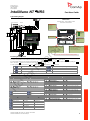
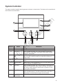
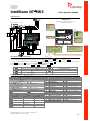
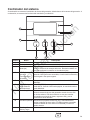
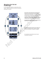
CAN INTERFACE
GENERATOR VOLTAGE
MEASUREMENT
T16 = Neutral
T17 = Phase 1
T18 = Phase 2
T19 = Phase 3
USB interface
L
COM
H
INTPUT TERMINALS
T10 = COM for analog inputs
T11 = binary input
T12 = binary input
T13 = binary/analog input – Low Fuel Level
T14 = binary/analog input – Coolan Temperature
T15 = binary/analog input – Oil Pressure
OUTPUT TERMINALS
T04 = binary output – Starter (6A)
T05 = binary output - Fuel Solenoid (6A)
T06 = binary output (500 mA)
T07 = binary input/output (500 mA)
POWER SUPPLY, D+
T01 = BATT -
T02 = D+
T03 = BATT +
G
ECU
DIESEL / GASOLINE ENGINE GENERATOR
LOAD
Fuel Solenoid
Battery
Sarter
Fuel Level Analog
Coolant Temperature Analog
Oil Pressure Analog
D+
-
+
Alarm
Ready To Load
Fuel Solenoid
Starter
COM
Remote Start And Load
Emergency Stop
CAN
L COM H
USB
Battery +
Battery -
D +
PC
L1
L2
L3
N
InteliNano NT
MRS Fast User Guide
Typical wiring diagram
Accessing the setup mode
Ensure the engine is stopped and the controller is in Manual mode (green LED above button Auto is turned off).
If you have not configured the custom initialization (init) screen then press and hold Stop button, then briefly press ▲ button and then Auto .
If you have already created your own init screen then press and hold Stop button and then briefly press ▲, the custom init screen will appear, keep holding the Stop
button. Then press ▼ to switch LCD to default init screen, and then press Auto.
To move up and down in the setup menu use ▲ and ▼ buttons. Press Start button to select or Stop button for exit.
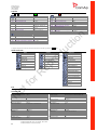
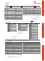
Basic settings
Input settings
Engine parameters and protections
ECU setting
Generator protections
Info
Output settings
Outputs and inputs
Output
code
Output source
Type
Terminal assignment
O00
Not Used
binary
T04, T05, T06, T07
O01
Starter
binary
T04
O02
Fuel Solenoid
binary
T04, T05, T06, T07
O03
Stop Solenoid
binary
T04, T05, T06, T07
O04
Alarm
binary
T04, T05, T06, T07
O07
Ready To Load
binary
T04, T05, T06, T07
O08
Prestart
binary
T04, T05, T06, T07
O09
ECU Power Relay
binary
T04, T05, T06, T07
O10
Choke
binary
T04, T05, T06, T07
O11
Glow Plugs
binary
T04, T05, T06, T07
Normally Open Contact – output
Normally Open Contact - input
button
Normally Closed Contact – output
Normally Closed Contact – input
button
User curves
I21
I23
I25
VDO Level %
VDO 5 Bar
VDO 40-120 °C
Datcon Level %
VDO 10 Bar
VDO 50-150 °C
Datcon 5 Bar
Datcon High °C
Datcon 7 Bar
Datcon Low °C
Datcon 10 Bar
Not selected
Not selected
Not selected
Input
code
Input source
Type
Terminal assignment
I00
Not Used
binary
T07, T11, T12, T13, T14, T15
I01
Emergency Stop
binary
T07, T11, T12, T13, T14, T15
I02
Remote Start/Stop
binary
T11
I03
Remote Start And Load
binary
T11
I04
Access Lock
binary
T07, T11, T12, T13, T14, T15
I07
GCB Feedback
binary
T07, T11, T12, T13, T14, T15
I10
External Warning 1
binary
T07, T11, T12, T13, T14, T15
I11
External Warning 2
binary
T07, T11, T12, T13, T14, T15
I12
External Warning 3
binary
T07, T11, T12, T13, T14, T15
I13
External Shutdown 1
binary
T07, T11, T12, T13,T14, T15
I14
External Shutdown 2
binary
T07, T11, T12, T13, T14, T15
I15
External Shutdown 3
binary
T07, T11, T12, T13, T14, T15
I20
Low Fuel Level
binary
T07, T11, T12, T13, T14, T15
I21
Fuel Level Analog
analog
T13, T14, T15
I22
Low Oil Pressure
binary
T07, T11, T12, T13, T14, T15
I23
Oil Pressure Analog
analog
T13, T14, T15
I24
High Coolant Temperature
binary
T07, T11, T12, T13, T14, T15
I25
Coolant Temperature Analog
analog
T13, T14, T15
Dimensions
Case dimensions: 118mm x108mm x 40mm
Panel Cutout: 96mm x 96mm
WARNING!
If D+ is not used, connect this terminal to battery positive!
3
Not for Reproduction

ComAp, spol s.r.o.
Kundratka 2359/17
180 00, Praha 8
Czech Republic
InteliNano-NT MRS, SW version 1.4, ©ComAp – March 2013
InteliNano-NT-MRS-1.4-Fast User Guide.pdf
Setpoints
Use ▲ and ▼ buttons to move or change value. Start button to select setpoint or confirm changes and Stop button to go back.
Basic settings
Setpoint
code
Setpoint name
B01
Nominal Voltage Ph-N
80 – 480 V
B02
Nominal Voltage Ph-Ph
80 – 600 V
B03
Nominal Frequency
50 Hz (1), 60 Hz (2)
B04
Connection Type
Mono Phase (1), SplitPhase (2),
3Ph3Wire (3), 3Ph4Wire (4)
B05
Units Format
Metric unit format (1), US unit
format (2)
B07
Zero Power Mode Delay
0-360 min
B08
Light Tower Mode
Disable (1), Enable (2)
B09
Nominal RPM
100-4000
Engine parameters and protections
Setpoint
code
Setpoint name
E01
Prestart Time
0-600 s
E02
Maximum Cranking Time
0-60 s
E03
Cooling Time
0-3600 s
E04
Oil Pressure Shutdown
0-10 Bar
E05
Coolant Temperature Shutdown
0 -150 °C
E06
Battery Undervoltage
8 – 40 V
E07
Warning Maintenance
0 – 10000 h
E08
Oil Pressure Starter Disengagement
Disable (1), Enable (2)
E09
Choke Time
0 – 3600 s
E10
Minimal Stabilization Time
1 – 300 s
Generator protections
Setpoint
code
Setpoint name
G01
Generator Overvoltage Shutdown
G02 – 200 %
G02
Generator Undervoltage Shutdown
0 - G01 %
G03
Generator Overfrequency Shutdown
G04 – 130 %
G04
Generator Underfrequency Shutdown
0 – G03 %
To apply all changes return to the main setup menu and restart the controller by pressing the Stop button.
Alarms and Events
Events
Manual Start
Remote Start
Manual Stop
Remote Stop
Auto On
Auto Off
Power On
Island Operation
Warnings
Warning Maintenance
Low Battery
Low Fuel Level
External Warning 1
External Warning 2
External Warning 3
ECU Communication Error
Shutdowns
Emergency Stop
Overspeed
Underspeed
Low Oil Pressure
High Coolant temperature
External Shutdown 1
External Shutdown 2
External Shutdown 3
GCB Fail
Generator Overvoltage
Generator Undervoltage
Generator Overfrequency
Generator Underfrequency
Generator CCW Rotation
Start Fail
Stop Fail
Battery Flat
ECU
For ECU configuration use PC software NanoEdit. For more details see InteliNano AMF Reference Guide.
Technical data
Power supply range
6-36 VDC
Power supply drop-out immunity
100 ms
Power consumption
35 – 295 mA
Zero Power Mode consumption
52 - 344 µA
Operating temperature
-20... 70 °C
Operating humidity
95% non-condensing (IEC/EN 60068-2-30)
Protection degree (front panel)
IP65 with GASKET 4x405 only
IP50 without gasket
Storage temperature
-30... 80 °C
Binary outputs (up to 4)
Low current outputs (2)
500 mA
High current output (2)
6 A (long term) / 10 A (short term)
Total output current
10 A (long term) / 16 A (short term)
Binary inputs (up to 6)
Input resistance
1,5 kΏ
Closed contact voltage
<2 V
Open contact voltage
>3,5 V
Analog inputs (up to 3)
Galvanic insulation
Not insulated
Electrical range
0 - 2500 kΏ
Resolution
0,1 Ώ
Precision
2 % ± 3 Ώ
Charging alternator preexcitation circuit
Excitation current
100 mA
Charging fail threshold
80 %
Generator/Mains measurements
Measurement input
3ph generator voltage
Measurement type
True RMS
Voltage range
480 V Ph-Ph (277 V Ph-N)
Max. measured voltage
340 V Ph-N
Voltage accuracy
1%
Frequency range
40 – 70 Hz
Frequency accuracy
1 %
4
Not for Reproduction

5
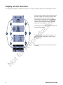
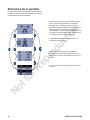
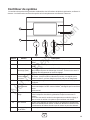
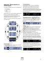
Position Button Description
A Up Arrow Press button for move up or value increasing.
B Down Arrow Press button for move down or value decreasing.
C Start Button Works in MANUAL MODE only. Press this button to initiate the
start sequence of the engine. This button is also used to confirm
changes in Setup Mode.
D Engine Operation
LED
GREEN LED is blinking if the engine is starting, cooling or stopping.
When the LED is solid, the engine is running and is loaded or is
ready to load.
E Auto Button Is dedicated for switching between AUTO and MANUAL operating
mode.
F Operating Mode
LED
GREEN LED is solid, the controller is in AUTO mode. When LED is
off, the controller is in MANUAL mode.
G Stop Button Works in MANUAL MODE only. Press this button to initiate the stop
sequence of the generator when engine is running. This button is
also used to cancel changes in setup mode, to go back or to exit
and for alarm confirmation.
H Alarm LED RED LED will blink when there is one or more active warning or
active shutdown alarm(s). The LED is solid when the active shut
down alarm is confirmed and the engine can’t be started.
J Graphic Black and
White Display
128 X 64 Pixels
Stop
Auto
Start
E
A
B
C
J
H
F D
G
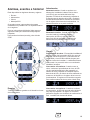
System Controller
The system controller, located inside the generator enclosure, is shown below. The features of the controller and
their locations are shown below.
Not for Reproduction

6 BRIGGSandSTRATTON.COM
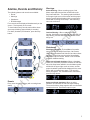
• The first screen contains basic information about
generator voltage and frequency measurement.
Also displayed is the position (status) of the
GCB (when so configured) and a running hours
counter. When any alarms occur, the general
warning symbol will be displayed on the upper
right corner of the display.
• The second screen contains detailed voltage and
frequency information.
• The third screen shows engine information – oil
pressure, coolant temperature, fuel level, and
battery voltage.
• The fourth screen shows the most recent alarms
or events.
Display Screen Structure
The displayed information is structured into screens. Use the up and down arrows to scroll through the screens.
Not for Reproduction

7
Alarms, Events and History
The following alarms and records are available:
• Events
• Warnings
• Shutdowns
• ECU Messages
Four records can be displayed simultaneously on the
screen. Total capacity is 10 records.
To view further history records, wait until the down
arrow stops blinking (approximately 3 seconds).
For alarm (shutdown) confirmation, press the Stop
button.
Events
Every event is saved in history with a running hours
stamp.
Warnings
Active Warning: When a warning occurs, O04
Alarm output will close and the red LED above the
Stop button will blink. The warning symbol will blink
in the upper right corner of the screen and the proper
warning symbol will be displayed in the event history
screen with a running hours stamp. Active warning
cannot be confirmed.
Inactive Warning: When a warning becomes
inactive, O04 Alarm output will open, the red LED will
stop blinking, and the warning symbol on the screen
will go out.
Shutdowns
Shutdown procedure: The InteliNano® controller
opens outputs O05 GCB Close/Open, O01 Starter,
O08 Prestart, and O02 Fuel Solenoid, and then closes
O03 Stop Solenoid to stop the engine immediately.
O04 Alarm output is closed. Active or not confirmed
protection disables starting.
Active unconfirmed shutdown: When a shutdown
occurs, the shutdown procedure will start, the red LED
above the Stop button will blink, the shutdown symbol
will blink in the upper right corner of screen, and the
proper shutdown symbol will be displayed in the event
history with a running hours stamp. The record in
history is negative. For shutdown alarm confirmation,
press the Stop button.
Active confirmed shutdown: When an active
shutdown is confirmed, the red LED stops blinking.
The record in history stays negative with a confirmation
symbol at the end. O04 Alarm output is open.
Not for Reproduction

8 BRIGGSandSTRATTON.COM
Inactive unconfirmed shutdown: O04 Alarm
output is closed, the red LED above the Stop button
will blink. The shutdown symbol will be displayed in
the upper right corner of the screen and the proper
warning symbol will be displayed in the event history
with a running hours stamp. For shutdown alarm
confirmation, press the Stop button.
Inactive confirmed shutdown: O04 Alarm output
is opened. It is possible to start the engine when all
shutdowns are inactive and confirmed.
ECU Messages
Diagnostic messages are displayed in the event
history behind the ECU Warning symbol. For Standard
J1939, SPN (Suspect Parameter Number) and FMI
(Failure Mode Identifier) are shown. A complete list of
text diagnostic messages for each ECU can be found
on The Power Portal.
Start and Stop Engine
Manual Mode
When the green LED above the Auto button is off, the
controller is in MANUAL mode. If there is no active
shut down alarm, you can start the engine by pressing
the Start button. The green LED will blink during the
starting, cooling, or stopping procedure. While the
engine is running, the green LED will light steadily.
The generator is ready to load.
Press the Stop button to stop the engine. The first
press will open the GCB and the next press will start
the cooling and stopping procedure. If you press
this button again, the controller will stop the engine
immediately. For fast engine stop, press and hold the
Stop button until the engine stops.
Auto Mode
When the green LED above the Auto button is on, the
controller is in AUTO mode. The engine cannot be
started by pressing the Start button. The controller will
automatically start the engine when all conditions for
starting and connecting loads have been met.
NOTICE
When in AUTO mode, the engine CANNOT
be stopped by pressing the Stop button.
Not for Reproduction

ComAp InteliNano NT
®
Manual del sistema de control
Generador de reserva
Copyright © Briggs & Stratton Power Products Group, LLC
Milwaukee, WI, EE. UU. Todos los derechos reservados.
80021813USCN
Modificación A
Not for Reproduction

10 BRIGGSandSTRATTON.COM
Tabla de contenido
Guia rápida de usuario ..........................11
Controlador del sistema
.........................13
Estructura de la pantalla
.........................14
Alarmas, eventos e historial
......................15
Eventos................................................ 15
Advertencias ........................................... 15
Cierres ................................................ 15
Mensajes ECU.......................................... 16
Arrancar y parar el motor ........................16
Modo manual ........................................... 16
Modo automático........................................ 16
Not for Reproduction

ComAp, spol s.r.o.
Kundratka 2359/17
180 00, Praha 8
Czech Republic
InteliNano-NT MRS, SW version 1.1, ©ComAp – February 2012 1
InteliNano-NT-MRS-1.1-Fast User Guide.pdf
G
ECU
DIESEL / GASOLINE ENGINE GENERATOR
LOAD
Fuel Solenoid
Battery
Sarter
Fuel Level Analog
Coolant Temperature Analog
Oil Pressure Analog
D+
-
+
Alarm
Ready To Load
Fuel Solenoid
Starter
COM
Remote Start And Load
Emergency Stop
CAN
L COM H
USB
Battery +
Battery -
D +
PC
L1
L2
L3
N
INTERFAZ CAN
MEDIDA DE TENSION
DE GENERADOR
T16 = Neutro
T17 = Fase 1
T18 = Fase 2
T19 = Fase 3
Interfaz USB
L
COM
H
TERMINALES DE ENTRADAS
T10 = COM para entradas analógicas
T11 = entrada binaria
T12 = entrada binaria
T13 = Entrada bin./anal. – Bajo nivel de comb
T14 = Entrada bin./anal. – Temperatura motor
T15 = Entrada bin./anal. – Presion aceite
TERMINALES DE SALIDAS
T04 = salida binaria – Arranque (6A
T05 = salida binaria - Solenoide comb (6A)
T06 = salida binaria (500 mA)
T07 = entrada/salida binaria (500mA)
ALIMENTACIÓN, D+
T01 = BAT -
T02 = D+
T03 = BAT +
InteliNano NT
MRS Guia rápida de usuario
Esquema típico
Accediendo al modo programación
Asegurese de que el motor está parado y en controlador en modo Manual (el LED verde sobre el botón Auto está apagado).
Si no ha configurado la pantalla inicial personalizada, mantenga presionado el botón Stop, pulse brevemente el botón ▲ y entonces pulse Auto.
Si ha creado su popia pantalla inicial, mantenga presionado el botón Stop y entonces pulse brevemente ▲, aparecerá la pantalla personalizada, mantenga presionado
el botón Stop. Entonces pulse ▼ para cambiar a la pantalla por defecto, y por último presione Auto.
Para desplazarse por el menú utilice los botones ▲ y ▼. Pulse Start para seleccionar o Stop para salir.
Basic settings (Parámetros básicos)
Input settings (Ajustes de entradas)
Engine parameters and protections (Parámetros y protecciones
de motor)
ECU setting (Ajustes ECU)
Generator protections (Protecciones de generador)
Info (Información)
Output settings (Ajuste de salidas)
Entradas y salidas
Salidas
código
Fuente de la salida
Tipo
Asignación del terminal
O00
No Usado
binario
T04 , T05, T06, T0
O01
Arranque
binario
T04
O02
Solenoide combustible
binario
T05
O03
Solenoide parada
binario
T05
O04
Alarma
binario
T04, T05, T06, T07
O07
Preparado para meter carga
binario
T04, T05, T06, T07
O08
Prearranque
binario
T04, T05, T06, T07
O09
Relé de Potencia ECU
binario
T04, T05, T06, T07
Contacto NC – salida
Contacto NA - entrada
Contacto NA – salida
Contacto NC – entrada
User curves
I21
I23
I25
VDO Nivell %
VDO 5 Bar
VDO 40-120 °C
Datcon Nivel %
VDO 10 Bar
VDO 50-150 °C
Datcon 5 Bar
Datcon High °C
Datcon 7 Bar
Datcon Low °C
Datcon 10 Bar
No seleccionado
No seleccionado
No seleccionado
Input
code
Input source
Type
Terminal assignment
I00
Not Used
binary
T07, T11, T12, T13, T14, T15
I01
Emergency Stop
binary
T07, T11, T12, T13, T14, T15
I02
Remote Start/Stop
binary
T11
I03
Remote Start And Load
binary
T11
I04
Access Lock
binary
T07, T11, T12, T13, T14, T15
I07
Estado GCB
binary
T07, T11, T12, T13, T14, T15
I10
Aviso Externo 1
binary
T07, T11, T12, T13, T14, T15
I11
Aviso Externo 2
binary
T07, T11, T12, T13, T14, T15
I12
Aviso Externo 3
binary
T07, T11, T12, T13, T14, T15
I13
Parada Externa 1
binary
T07, T11, T12, T13,T14, T15
I14
Parada Externa 2
binary
T07, T11, T12, T13, T14, T15
I15
Parada Externa 3
binary
T07, T11, T12, T13, T14, T15
I20
Bajo Nivel de Combustible
binary
T07, T11, T12, T13, T14, T15
I21
Nivel de Combustible Analog.
analog
T13, T14, T15
I22
Baja Presión de Aceite
binary
T07, T11, T12, T13, T14, T15
I23
Presión de Aceite Analog.
analog
T13, T14, T15
I24
Alta Temperatura Refrigerante
binary
T07, T11, T12, T13, T14, T15
I25
Temperatura Refrig. Analog
analog
T13, T14, T15
Dimensiones
Dimensiones de caja:118mm x108mm x40mm
Corte panel: 96mm x 96mm
AVISO!
Si no se utilize el D+, conectar este terminal al positivo de batería!
11
Not for Reproduction

ComAp, spol s.r.o.
Kundratka 2359/17
180 00, Praha 8
Czech Republic
InteliNano-NT MRS, SW version 1.1, ©ComAp – February 2012
InteliNano-NT-MRS-1.1-Fast User Guide.pdf
Setpoints
Utillice los pulsadores ▲ y ▼ para moverse o cambiar valores. El pulsador Start para seleccionar el parámetro o confirmar los cambios y el Stop para salir.
Basic settings
Ajuste
código
Nombre parámetro
B01
Tension Nominal F-N
80 – 480 V
B02
Tensión Nominal F-F
80 – 600 V
B03
Frecuencia Nominal
50 Hz (1), 60 Hz (2)
B04
Tipo Conexión
Monofásica (1),Doble delta (2),
3F3Hilos (3), 3F4Hilos (4)
B05
Formato Unidades
Formato Metrico (1), formato US
(2)
B07
Retardo Modo Zero Consumo
0-360 min
Engine parameters and protections
Ajuste
código
Nombre parámetro
E01
Tiempo Prearranque
0-600 s
E02
Máximo Tiempo Arranque
0-60 s
E03
Tiempo Enfriamiento
0-3600s
E04
Parada Presion Aceite
0-10 Bar
E05
Parada Temperatura Refrigerante
0 -150 °C
E06
Baja tension Batería
8 – 40 V
E07
Aviso Mantenimiento
0 – 10000 h
E08
Detección de arranque por presión
Disable (1), Enable (2)
Generator protections
Ajuste
código
Nombre parámetro
G01
Parada Sobretensión de generador
G02 – 200 %
G02
Parada Baja tension de generador
0 - G01 %
G03
Parada Sobrefrecuencia de generador
G04 – 130 %
G04
Parada Baja frecuencia de generador
0 – G03 %
Para que se apliquen todos los cambios, vuelva a la manu principal de programación y reinicie el controlador pulsando el botón Stop.
Alarmas y Eventos
Events
Arranque Manual
Arranque Remoto
Parada Manual
Parada Remota
Auto On
Auto Off
Encendido
Operación en Isla
Warnings
Aviso Mantenimiento
Batería Baja
Bajo Nivel Combustible
Aviso Externo 1
Aviso Externo 2
Aviso Externo 3
ECU Error Comunicación
Shutdowns
Parada Emergencia
Sobrevelocidad
Baja velocidad
Baja presión de Aceite
Alta Temperatura motor
Parada Externa 1
Parada Externa 2
Parada Externa 3
Fallo GCB
Sobretensión Generador
Baja Tensión Generador
Alta frecuencia Generador
Baja frecuencia Generador
Sentido Giro Generador
Fallo de Arranque
Fallo de Parada
Batería descargada
ECU
Para la configuración ECU utilice el software para PC NanoEdit. Para más detalles vea ‘InteliNano AMF Reference Guide’.
Información Técnica
Rango de alimentación
6-36VDC
Inmunidad caida de tensión
100ms
Consumo
35 – 295mA
Consumo en modo Zero Consumo
52 - 344 µA
Temperatura de funcionamiento
-20... 70°C
Humedad de funcionamiento
95% no-condensado (IEC/EN 60068-2-30)
Grado de protección (frente panel)
IP65
Temperature almacenamiento
-30... 80°C
Salidas binarias (hasta 4)
Salidas de bajo corriente (2)
500mA
Salidas de alta corriente (2)
6A (permanente) / 10A (puntual)
Corriente de Salida Total
10A (permanente) / 16A (puntual)
Entradas binarias (hasta 6)
Resistencia de Entrada
1,5 kΏ
Tensión contacto cerrado
<2V
Tensión contacto abierto
>3,5V
Entradas Analógicas (hasta 3)
Aislamiento Galvánico
No aislado
Rango eléctrico
0 - 2500kΏ
Resolución
0,1 Ώ
Precisión
2% ± 3Ώ
Circuito de preexcitación del Alternador Cargabaterías
Corriente de Excitación
100mA
Umbral fallo de carga
80%
Medidas Generador/Red
Medida entrada
Tension de generador 3f, tensión de red 3f
Tipo medición
RMS verdadero
Rango de tensión
480V F-F (277V F-N)
Max. tension medida
340V F-N
Preción de tensión
1%
Rango de frecuencia
40 – 70 Hz
Precisión de frecuencia
1%
12
Not for Reproduction

13
Stop
Auto
Start
Posición Botón Descripción
A Flecha hacia arriba Pulse el botón para moverse hacia arriba o incrementar un valor.
B Flecha hacia abajo Pulse el botón para moverse hacia abajo o disminuir un valor.
C Botón Start
(Arranque)
Funciona únicamente en MODO MANUAL. Pulse este botón para
iniciar la secuencia de arranque del motor. Este botón también se
usa para confirmar los cambios en el modo de ajuste.
D LED Engine
Operation
(Funcionamiento
del motor)
El LED VERDE parpadea si el motor arranca, se enfría o para.
Cuando el LED permanece encendido, el motor está funcionando y
está cargado o listo para cargarse.
E Botón Auto Sirve para cambiar entre el modo de funcionamiento AUTO y
MANUAL.
F LED Operating
Mode (Modo de
funcionamiento)
Si el LED VERDE permanece encendido, el controlador está en
modo AUTO. Cuando el LED está apagado, el controlador está en
modo MANUAL.
G Botón Stop (Paro) Funciona únicamente en MODO MANUAL. Pulse este botón para
iniciar la secuencia de paro del generador cuando el motor está
en funcionamiento. Este botón también se usa para cancelar
los cambios en el modo de ajuste, regresar o salir y para la
confirmación de las alarmas.
H LED Alarm (Alarma) El LED ROJO parpadea cuando hay una o más advertencias
activas o alarmas de cierre activo. El LED permanece encendido
cuando la alarma de cierre activo es confirmada y el motor no
puede arrancar.
J Pantalla gráfica en
blanco y negro
128 X 64 pixeles
A
B
C
G
E
J
H
F D
Controlador del sistema
A continuación se muestra el controlador de sistema del generador, ubicado dentro de la carcasa del generador. A
continuación, se muestran las funciones del controlador y su ubicación.
Not for Reproduction

14 BRIGGSandSTRATTON.COM
Estructura de la pantalla
La información que se muestra está estructurada en
pantallas. Use las flechas hacia arriba y hacia abajo
para desplazarse por las pantallas.
• La primera pantalla contiene información básica
sobre la tensión del generador y la medición
de frecuencia. También contiene la posición
mostrada (estado) del GCB (únicamente cuando
está configurada) y el contador de horas de
funcionamiento. Cuando alguna alarma se activa,
se muestra el símbolo general de advertencia en
la esquina superior derecha de la LCD.
• La segunda pantalla contiene la tensión y la
información de frecuencia.
• La tercera pantalla muestra la información
del motor: presión del aceite, temperatura del
refrigerante, nivel de combustible y tensión de la
batería.
• La cuarta pantalla muestra las últimas alarmas o
eventos.
Not for Reproduction

15
Alarmas, eventos e historial
Están disponibles las siguientes alarmas y registros:
• Eventos
• Advertencias
• Cierres
• Mensajes ECU
Se pueden mostrar cuatro registros de manera
simultánea en la pantalla LCD. La capacidad total es
de 10 registros.
Para ver más registros del historial, debe esperar 3
segundos hasta que la flecha hacia abajo deje de
parpadear.
Para confirmar la alarma (cerrarla), pulse el botón
STOP.
Eventos
Todos los eventos se guardan en el historial con horas
de funcionamiento.
Advertencias
Advertencia activa: Cuando se produce una
advertencia, la salida de la alarma O04 se cierra
y el LED rojo que está arriba del botón Stop
parpadea. El símbolo de advertencia parpadea en
la esquina superior derecha de la LCD y el símbolo
de advertencia adecuado se muestra en el historial
con el registro de las horas de funcionamiento. La
advertencia activa no se puede confirmar.
Advertencia inactiva: Cuando una advertencia
se vuelve inactiva, la salida de la alarma
O04 se abre, el LED rojo que está arriba del
botón Stop deja de parpadear y el símbolo de
advertencia en la pantalla principal se apaga.
Cierres
Procedimiento de cierre: El controlador InteliNano®
abre las salidas O05 cerrar/abrir GCB, O01 motor de
arranque, O08 arranque previo y O02 solenoide de
combustible y cierra la O03 solenoide de paro para
detener el motor de inmediato. La salida O04 alarma
está cerrada. La protección activa o no confirmada
inhabilita el arranque.
Cierre activo sin confirmar: Cuando ocurre un
cierre, comienza el procedimiento de cierre, el LED
rojo que está arriba del botón Stop parpadea, el
símbolo de cierre parpadea en la esquina superior
derecha de la LCD y el símbolo de cierre adecuado se
muestra en el historial con el registro de las horas de
funcionamiento. El registro en el historial es negativo.
Para confirmar alarma de cierre, pulse el botón Stop.
Cierre activo sin confirmar: Cuando se confirma
un cierre activo, el LED rojo que está arriba del botón
Stop deja de parpadear. El registro en el historial
permanece negativo con el símbolo de confirmación al
final. La salida O04 alarma está abierta.
Not for Reproduction

16 BRIGGSandSTRATTON.COM
Cierre inactivo sin confirmar: La salida O04 alarma
está cerrada, el LED rojo que está arriba del botón
Stop parpadea. El símbolo de cierre se muestra en
la esquina superior derecha de la LCD y el símbolo
de advertencia adecuado se muestra en el historial
con el registro de las horas de funcionamiento. Para
confirmar la alarma de cierre, pulse el botón Stop.
Cierre inactivo confirmado: La salida O04 alarma
está abierta. Es posible arrancar el motor cuando
todos los cierres están inactivos y confirmados.
Mensajes ECU
Los mensajes de diagnóstico se leen y muestran
en el historial detrás del símbolo de advertencia
ECU. Para el J1939 estándar se muestran el número
de parámetrosospechoso (Suspect Parameter
Number, SPN) y el identificador de modo de fallo
(Failure Mode Identifier, FMI). Se puede encontrar
una lista completa de los mensajes de diagnóstico
de texto para cada ECU en The Power Portal.
Arrancar y parar el motor
Modo manual
El LED verde que está arriba del botón Auto está
apagado (el controlador está en modo MANUAL).
Cuando no hay alarmas de cierre activa, puede
arrancar el motor pulsando el botón Start. El LED
verde que está arriba del botón parpadea. El LED
parpadea durante el procedimiento de arranque,
enfriamiento y paro. Cuando el motor ya arrancó, el
LED verde deja de parpadear y se ilumina de manera
permanente. El generador está listo para cargar.
Pulse el botón Stop para parar el motor. La primera
vez que lo pulse se abrirá el GCB y la siguiente vez
iniciará el procedimiento de enfriamiento y de paro. Al
pulsar este botón de nuevo, el controlador detiene el
motor de inmediato. Para parar rápidamente el motor,
pulse y mantenga oprimido el botón Stop hasta que el
motor se pare.
Modo automático
El LED verde que está arriba del botón Auto está
encendido (el controlador está en modo AUTO).
No puede arrancar el motor ni conectar la carga
pulsando el botón Start. El controlador arrancará
automáticamente cuando se cumplan todas las
condiciones para el arranque y la conexión de carga.
AVISO
El motor en modo AUTO NO PUEDE pararse
pulsando el botón Stop.
Not for Reproduction

ComAp InteliNano NT
®
Manuel du Contrôleur Système
Système de génératrice auxiliaire
Copyright © Briggs & Stratton Power Products Group, LLC
Milwaukee, WI, USA. Tous droits réservés.
80021813USCN
Révision A
Not for Reproduction

18 BRIGGSandSTRATTON.COM
Table des matières
Guide de démarrage rapide ......................19
Contrôleur de système
..........................21
Structure de l’écran d’affichage
...................22
Alarmes, Événements et Historiques
..............23
Événements ............................................ 23
Avertissements ......................................... 23
Arrêts ................................................. 23
Messages ECU ......................................... 24
Démarrage et arrêt du moteur ....................24
Mode manuel .......................................... 24
Mode automatique....................................... 24
Not for Reproduction

19
Guide de démarrage rapide n’est pas disponible en Français
Not for Reproduction

20 BRIGGSandSTRATTON.COM
Guide de démarrage rapide n’est pas disponible en Français
Not for Reproduction
La page charge ...
La page charge ...
La page charge ...
La page charge ...
-
 1
1
-
 2
2
-
 3
3
-
 4
4
-
 5
5
-
 6
6
-
 7
7
-
 8
8
-
 9
9
-
 10
10
-
 11
11
-
 12
12
-
 13
13
-
 14
14
-
 15
15
-
 16
16
-
 17
17
-
 18
18
-
 19
19
-
 20
20
-
 21
21
-
 22
22
-
 23
23
-
 24
24


Simplicity 076165-01 Manuel utilisateur
- Catégorie
- Mesure, test
- Taper
- Manuel utilisateur
dans d''autres langues
Documents connexes
Autres documents
-
Reloop Jockey III Master edition Manuel utilisateur
-
Avaya 7316E Guide d'installation
-
BENDIX SD-23-7541F Manuel utilisateur
-
-
 FINIMETAL TAHITI SPEED AIR Le manuel du propriétaire
-
 FINIMETAL TAHITI Le manuel du propriétaire
-
Klein Tools VDV500-063 Manuel utilisateur
-
MEDC DB3B Tehcnical Le manuel du propriétaire
-
Televes Power patch cord Manuel utilisateur

