Powerfist 9009697 Le manuel du propriétaire
- Catégorie
- Ponceuses électriques
- Taper
- Le manuel du propriétaire

V4.0 9009697
Please read and understand all instructions before use. Retain this manual for
future reference.
User Manual
Combination Belt and
Disc Sander

9009697 Combination Belt and Disc Sander V4.0
2 For technical questions call 1-800-665-8685
SPECIFICATIONS
Wheel Size 5 in.
Belt Size
1 x 30 in.
Horsepower 1/3 HP
Voltage Rating 120V AC
Current Rating 2.3A
Frequency Rating 60Hz
No Load Speed
3,450 RPM
INTRODUCTION
Versatile and powerful sanding station fits on any workbench. Features a
powerful 1/3 HP induction motor, dust-resistant switch and adjustable
aluminum work table and gauge. Lightweight aluminum frame and sheet metal
base allow for easy portability. Standard 80 grit sanding disc and belt included.
Removable belt backstop for buffing, polishing and removing rust from curved
workpieces. Removable side panel with locking knob for quick belt changes.
Belt tracking control knob for easy belt adjustments. Rear and side exhaust dust
chutes hook up to dust collection systems for easy clean-up.
SAFETY
WARNING! Read and understand all instructions before using this tool. The
operator must follow basic precautions to reduce the risk of personal injury
and/or damage to the equipment.
Keep this manual for safety warnings, precautions, operating or inspection and
maintenance instructions.
Combination Belt and
Disc Sander

V4.0 Combination Belt and Disc Sander 9009697
Visit www.princessauto.com for more information 3
HAZARD DEFINITIONS
Please familiarize yourself with the hazard notices found in this manual. A notice
is an alert that there is a possibility of property damage, injury or death if certain
instructions are not followed.
DANGER! This notice indicates an immediate and specific hazard that will
result in severe personal injury or death if the proper precautions
are not taken.
WARNING! This notice indicates a specific hazard or unsafe practice that
could result in severe personal injury or death if the proper
precautions are not taken.
CAUTION! This notice indicates a potentially hazardous situation that may result
in minor or moderate injury if proper practices are not taken.
NOTICE! This notice indicates that a specific hazard or unsafe practice will
result in equipment or property damage, but not personal injury.
WORK AREA
1. Operate in a safe work environment. Keep your work area clean, well-lit
and free of distractions. Place lights so you are not working in a shadow.
2. Keep anyone not wearing the appropriate safety equipment away from the
work area.
3. Store unused tools properly in a safe and dry location to prevent rust or
damage. Lock tools away and keep out of the reach of children.
4. Do not install or use in the presence of flammable gases, dust or liquids.
PERSONAL SAFETY
WARNING! Wear personal protective equipment approved by the Canadian
Standards Association (CSA) or American National Standards Institute (ANSI).
PERSONAL PROTECTIVE EQUIPMENT
1. Always wear impact safety goggles that provide front and side protection
for the eyes. Eye protection equipment should comply with CSA Z94.3-07
or ANSI Z87.1 standards based on the type of work performed.

9009697 Combination Belt and Disc Sander V4.0
4 For technical questions call 1-800-665-8685
2. Wear the appropriate type of full-face shield in addition to safety googles,
as the work can create chips, abrasive or particulate matter.
3. Do not wear gloves when operating a tool that can snag the material and
pull the hand into the tool.
4. Wear protective clothing designed for the work environment and tool.
5. Non-skid footwear is recommended to maintain footing and balance in the
work environment.
6. Wear a NIOSH approved respirator when working on materials that
produce hazardous fumes, dust or particulate matter.
PERSONAL PRECAUTIONS
Control the tool, personal movement and the work environment to avoid
personal injury or damage to tool.
1. Do not operate any tool when tired or under the influence of drugs, alcohol
or medications.
2. Avoid wearing clothes or jewelry that can become entangled with the
moving parts of a tool. Keep long hair covered or bound.
3. Do not overreach when operating a tool. Proper footing and balance
enables better control in unexpected situations.
ELECTRICAL SAFETY
WARNING! Do not touch or handle a live tool with any part of your body that
is wet or damp. Wet skin reduces resistance to electrical current,
increasing the danger of a serious or fatal shock.
WARNING! To reduce risk of electric shock, be certain that the plug is
connected to a properly grounded receptacle.
1. Disconnect tool from power source before cleaning, servicing, changing
parts/accessories or when not in use.
2. Protect yourself against electric shocks when working on electrical
equipment. Avoid body contact with grounded surfaces. There is an
increased chance of electrical shock if your body is grounded.
3. Do not expose the tool to rain or wet conditions. Water entering a tool will
increase the risk of electric shock.

V4.0 Combination Belt and Disc Sander 9009697
Visit www.princessauto.com for more information 5
4. Do not disconnect the power cord in place of using the ON/OFF switch on
the tool. This will prevent an accidental start-up when the power cord is
plugged into the power supply.
a. In the event of a power failure, turn off the machine as soon as the
power is interrupted. The possibility of accidental injury could occur if
the power returns and the unit is not switched off.
5. Do not alter any parts of the tool or accessories. All parts and accessories are
designed with built-in safety features that may be compromised if altered.
6. Make certain the power source conforms to requirements of your
equipment (see Specifications).
7. When wiring an electrically driven device, follow all electrical and safety
codes, as well as the most recent Canadian Electrical Code (CE) and
Canadian Centre for Occupational Health and Safety (CCOHS).
8. Grounded tools must be plugged into an outlet that is properly installed and
grounded in accordance with all codes and ordinances. Check with a qualified
electrician if you are in doubt as to whether the outlet is properly grounded. If
the tool should electronically malfunction or break down, grounding provides a
low resistance path to carry electricity away from the user.
a. Never remove the grounding prong or modify the plug in any way, as
this will render the tool unsafe.
b. Do not use any adapter plugs.
WARNING! All wiring should be performed by a qualified electrician.
POWER TOOL PRECAUTIONS
1. DO NOT use any power tool with a malfunctioning power switch or control.
A power tool that fails to respond to the controls is dangerous and could
cause an injury. A qualified technician must repair and verify the power tool
is operating correctly before it can be used.
2. Do not allow the tool to run without load for an extended period of time, as
this will shorten its life.
3. Do not cover the air vents. Proper cooling of the motor is necessary to
ensure normal life of the tool.
4. Avoid unintentional starting. Ensure the switch is off when connecting to
the power source.

9009697 Combination Belt and Disc Sander V4.0
6 For technical questions call 1-800-665-8685
5. Disconnect the power source before installing or servicing the tool.
6. After making adjustments, make sure that any adjustment devices are
securely tightened.
7. Remove adjusting keys and wrenches before using the tool. The tool may
eject an attached wrench or a key and cause an injury to you or a
bystander.
8. Never force the tool. Forcing the tool will slow it down and could cause the
cutting accessory to bind or kickback. Excessive pressure could break the
tool, resulting in damage to your workpiece or cause serious personal
injury. If your tool runs smoothly under no load, but does not run smoothly
under load, then excessive pressure is being used. Apply gentle pressure
and allow the tool to do the work.
9. Do not touch an operating motor. Motors can operate at high temperatures
and can cause a burn injury.
10. Never point the tool towards yourself. It could inflict an injury.
11. Never touch the cutting accessory or workpiece during or immediately after
use. They may be hot and could inflict a burn injury.
12. Keep hands and fingers away from sanding area. Any part of body coming in
contact with moving parts could cause an injury.
13. This tool will not stop moving immediately. Do not lay the tool down or
leave it unattended until it has come to a complete stop. A part that is
moving could make the tool jump or grab a surface and pull the tool out of
your control.
14. Never operate the tool with the safety guard removed. Never clamp or tie
the guard into the open position.
SPECIFIC SAFETY PRECAUTIONS
WARNING! DO NOT let comfort or familiarity with product (gained from
repeated use) replace strict adherence to the tool safety rules. If you use
this tool unsafely or incorrectly, you can suffer serious personal injury.
1. Use the correct tool for the job. This tool was designed for a specific function.
Do not modify or alter this tool or use it for an unintended purpose.

V4.0 Combination Belt and Disc Sander 9009697
Visit www.princessauto.com for more information 7
2. Do not use the tool if any parts are damage broken or misplaced. Repair or
replace the parts.
3. Work in well ventilated rooms. Whenever possible use a dust collection
system. Use an appropriate dust respirator when sanding for an extended
period of time. This will help prevent breathing in the fine dust created
while sanding.
CAUTION! Some wood contains preservative such as copper chromium
arsenate (CCA), which can be toxic. When sanding these materials extra
care should be taken to avoid inhalation and minimize skin contact.
4. Always make sure the work surface is free from nails and other
foreign objects.
UNPACKING
WARNING! Do not operate the tool if any part is missing. Replace the
missing part before operating. Failure to do so could result in a malfunction
and personal injury.
Remove the parts and accessories from the packaging and inspect for damage.
Make sure that all items in the parts list are included. Make sure that all items in
the Identification Key are included.
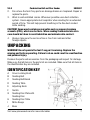
IDENTIFICATION KEY
A Cover Locking Knob
B Sanding Belt
C Sanding Belt Board
D Sanding Table
E Adjusting Knob
F Switch
G Sanding Disc Plate with
Sanding Disc
H Sanding Disc Table
I Mitre Gauge
J Base

9009697 Combination Belt and Disc Sander V4.0
8 For technical questions call 1-800-665-8685
K Table Locking Knob
L Rubber Foot
ASSEMBLY & INSTALLATION
Numbered references in parenthesis (#1) refer to the included Parts List. Letter
references in parenthesis (A) refer to the included Identification Key. Dashed
numbers in parenthesis (Fig. 1-1) refer to a specific point in an illustration or image.
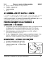
POSITIONING THE BELT AND DISC SANDER
1. Select a suitable work place before using the belt and disc sander. Your
work place should be well illuminated and enables you to attach a dust
collection system or a vacuum cleaner.
2. Place the belt and disc sander on a workbench or mount the sander on a
table with screws.
3. If this is not possible, use the included
rubber feet. If the rubber feet are not
attached, press them from the upper side
of the base through the edge openings.
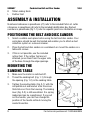
MOUNTING THE
SANDING TABLE
1. Make sure the motor is switched off.
2. Thread the sanding belt (Fig. 1-1) through
the opening (Fig. 1-2) in the sanding table.
3. Tighten the sanding table (Fig. 2-1) with the
compatible nut and washer onto the screw
that sticks out from the housing. The locking
lever (Fig. 2-2) is still assembled. It is spring
loaded and can be repositioned. If you pull
out the handle, you can then change the
position of the handle without moving the
inside thread bar.
Fig. 1
Fig. 2

V4.0 Combination Belt and Disc Sander 9009697
Visit www.princessauto.com for more information 9
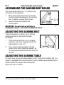
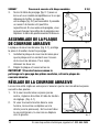
ASSEMBLING THE SANDING BELT BOARD
The sanding belt board (Fig. 3-1) protects the
work piece during sanding.
1. Mount the sanding belt board so that the
board touches the backside of the sanding
belt. To adjust, unscrew both screws.
2. Adjust the board and tighten the
screws again.
IMPORTANT! For work such as polishing or
sanding bent pieces, remove the sanding belt board.
ADJUSTING THE SANDING BELT
The belt adjustment is factory set so that the
sanding belt will run centrically through
the pulleys.
1. If the sanding belt does not run straight,
adjust the run of the sanding belt with the
adjusting knob. (Fig. 4-1)
2. If you turn the knob clockwise, the belt
moves to the right (facing the sander). By
turning counter-clockwise the belt moves to
the left.
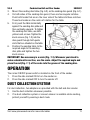
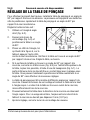
ADJUSTING THE SANDING TABLE
For most work, mount the sanding table at a 90° angle to the sanding belt. The
sander is equipped with a positive stop in order to enable quick positioning the
sander table to 90° angle to the sanding belt.
Adjust the stop as follows:
Fig. 3
Fig. 4

9009697 Combination Belt and Disc Sander V4.0
10 For technical questions call 1-800-665-8685
1. Use a right angle triangle (Fig. 5-2).
2. Loosen the locking lever (Fig. 5-3)
and position the table to a visual
judgment of 90°.
3. Place the one leg of the triangle,
as shown in figure 5, on the table
and hold the other leg against the
sanding belt. Check that the table
is 90° angle to the belt. Adjust
the table if necessary.
4. If the table surface is 90° angle to the belt, tighten the hex socket
screw (Fig. 5-4) on the upper end of the table as far as possible using a
hex key (Fig. 5-1). The bottom side of the screw should slightly touch the
plate underneath the table. Now you can reposition the table to exactly a
90° angle without new adjustments.
5. The sanding table can be mounted in different angles to the belt. Loosen
the locking lever and tilt the table up to the required angle. The table edge
is situated in front of the belt but far enough away from the belt.
6. Slowly push the table in the direction to the belt observing the required
incline. For safe use, the gap between the table edge and the belt should
not be higher than 2 mm (0.07 in.).
7. After adjustment, tighten the locking lever again.
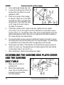
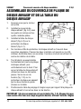
ASSEMBLING THE SANDING DISC PLATE COVER
AND THE SANDING
DISC TABLE
1. Make sure the motor is
switched off.
2. Mount the sanding disc
cover (Fig. 6-3) with the four
enclosed screws and the
four flat washers.
Fig. 5
Fig. 6

V4.0 Combination Belt and Disc Sander 9009697
Visit www.princessauto.com for more information 11
3. Mount the sanding disc table (Fig. 6-2) on the sanding disc guard (Fig. 6-1).
4. On both sides of the sanding disc guard, there are two angular notches.
Push both hooks that are on the inner side of the table into these notches.
These two hooks are the centre of rotation for the table.
5. First, push the table horizontally
against the sanding disc plate and
then vertically upwards. To tighten
the sanding disc table, use both
yellow knob screws. Tighten the
knob screws (Fig. 7-2) into the
disc guard through both guide
slots that are situated on the table.
6. Position the sanding table to the
required angle to the sanding
disc plate and tighten the two
knob screws.
IMPORTANT! One accessory is a scale (Fig. 7-3). Whenever you intend to
make a double mitre section, use the scale. Adjust the required angle and
place the rod (Fig. 7-1) of the scale into the groove of the sanding disc.
OPERATION
The rocker ON/OFF power switch is located on the front of the sander.
1. Press the side marked ON to turn the sander on.
2. Press the side marked OFF to turn the sander off.
DUST COLLECTION SYSTEM
For dust collection, two adapters are provided with the belt and disc sander.
1. Use the dust collection whenever possible.
2. If no dust collection system or vacuum cleaner is available while sanding,
protect yourself by wearing a dust mask.
Fig. 7

9009697 Combination Belt and Disc Sander V4.0
12 For technical questions call 1-800-665-8685
CARE & MAINTENANCE
1. Maintain the tool with care. A tool in good condition is efficient, easier to
control and will have fewer problems.
2. Inspect the tool fittings, alignment, hoses and power supply cord periodically.
Have damaged or worn components repaired or replaced by an authorized
technician. Only use identical replacement parts when servicing.
3. Follow instructions for lubricating and changing accessories.
4. Only use accessories intended for use with this tool.
5. Keep the tool handles clean, dry and free from oil/grease at all times.
6. Although the sander does not require user maintenance, the sander should
be kept clean. Wipe the sander with a clean cloth and periodically blow out
all areas with compressed air or use a brush. Do not use harsh chemicals
or solvents to clean the sander. These chemicals could seriously damage
the plastic housing.
7. Although attaching a dust collection, sanding dust may accumulate behind
the bracket cover. Therefore, remove the cover as described from time to
time and clean the interior with a brush or vacuum cleaner.
8. Avoid overloading the sander. Overloading will result in considerable
reduction of speed and efficiency and the unit will become hot. In this
event, run the sander at a “no load” condition for a minute or two.
9. Regularly inspect all mountings and screws to ensure tightness. Should
any screws become loose, tighten immediately.
10. Maintain the tool’s labels and name plates. These carry important information.
If unreadable or missing, contact Princess Auto Ltd. for replacements.
WARNING! Only qualified service personnel should repair the tool. An
improperly repaired tool may present a hazard to the user and/or others.

V4.0 Combination Belt and Disc Sander 9009697
Visit www.princessauto.com for more information 13
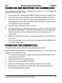
REMOVING AND INSERTING THE SANDING BELT
Before making any adjustments or changing any accessory, turn off the tool and
unplug it from its power source.
1. Unscrew the cover locking knob (#25) and remove the acrylic glass cover.
2. Unscrew both hex screws that secure the sanding belt bracket cover (#27).
3. Remove the cover. The rear drive wheel is spring supported. Press the
adjusting knob (#49) to push the wheel slightly forward in order to remove
the sanding belt out of the wheels.
4. Insert the new sanding belt onto the wheels.
5. Turn the belt with your hand and observe the movement. If the belt runs in
the middle of the wheels or if the belt slides sideways. Turn the adjusting
knob to adjust the position of the wheel and to correct the run of the
sanding belt.
6. Attach the sanding belt bracket cover again and tighten the cover with the
hex screws.
7. Place the acrylic glass cover onto the bracket cover and secure them with
the cover locking knob.
REMOVING THE SANDING DISC
The sanding disc (#67) is glued to the sanding disc plate (#70).
Before making any adjustments or changing any accessory, turn off the tool and
unplug it from its power source.
1. To remove the sanding disc, detach the sanding disc table (#64) and the
sanding disc guard (#71).
2. Carefully remove the used sanding disc.
3. Remove the remaining adhesive residues.
4. Stick a new sanding disc of the same diameter onto the disc plate.
5. After fixing a new sanding disc, attach the sanding disc guard and the
sanding disc table onto the sander.

9009697 Combination Belt and Disc Sander V4.0
14 For technical questions call 1-800-665-8685
DISPOSAL
Recycle a tool damaged beyond repair at the appropriate facility.
Contact your local municipality for a list of disposal facilities or by-laws for
electronic devices, batteries, oil or other toxic liquids.
TROUBLESHOOTING
Visit a Princess Auto Ltd. location for a solution if the tool does not function
properly or parts are missing. If unable to do so, have a qualified technician
service the tool.

V4.0 Combination Belt and Disc Sander 9009697
Visit www.princessauto.com for more information 15
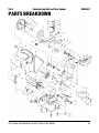
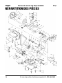
PARTS BREAKDOWN

9009697 Combination Belt and Disc Sander V4.0
16 For technical questions call 1-800-665-8685
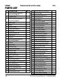
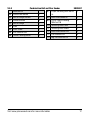
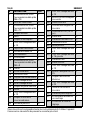
PARTS LIST
#
DESCRIPTION
QTY
1 Hex Screw/Flat Washer
Assembly M6x18
2
2 Rubber Foot 4
3 Hex Screw/Flat Washer
Assembly M4x12 4
4 Base Plate 1
5 Base 1
6 Switch Plate 1
7 Hex Screw M5x10 2
8
End Cap
1
9
Wave Washer 35
1
10 Capacitor 1
11 Switch 1
12 Hex Screw/Flat Washer
Assembly M4x8
2
13
Stator
1
14 Cord Clip 1
15 Cord & Plug 1
16
Capacitor Support
1
17 Hex Nut M8 2
18
Hex Nut M6
1
19 Belt Guard Plate 1
20 Rotor 1
21 Hex Screw M4x10 7
22
Sanding Belt Limiting Plate
1
23
Flat Washer D4
6
24 Hex Screw M4x10 2
25
Cover Locking Knob
1
26 Belt Guard 1
27
Belt Bracket Cover
1
28
Belt #100 (1 in. x 30 in.)
1
29
Idler Wheel
2
30 Spring Washer D15 2
31 Bearing 6202 4
32
Idler Shaft
1
33 Hex Screw M6x8 1
34
Hex Screw M5x16 Left
1
35 Locking Washer 1
36 Driving Wheel 1
37 Hex Screw M6x10 3
38 Hex Bolt M10x25 1
39
Sanding Belt Support
1
40 Hex Screw M6x20 1
41
Belt Working Table
1
42 Big Flat Washer D8 1
43
Locking Knob Assembly
1
44 Adjusting Shaft Guard 1
45 Adjusting Spring 1
46
Nut M10
1
47
Adjusting Fixing Plate
1
48 Adjusting Spring I 1
49 Adjusting Knob 1
50
Hex Screw ST4.2x10
4
51 Spring Column Pin
ȹ
3x20 1
52
Adjusting Shaft
1
53 Adjusting Spring II 1
54
Big Flat Washer D5
2
55 Split Washer 3.5 1
56 Sanding Disc Cover 1
57
Pointing Arrow
1
58
Outer Tooth Locking
2

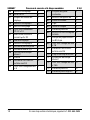
V4.0 Combination Belt and Disc Sander 9009697
Visit www.princessauto.com for more information 17
Washer D4
59 Hex Screw M4x6 1
60
Mitre Gauge Handle
1
61 Hex Knob M4 4
62 Mitre Gauge 1
63
Rod
1
64
Disc Table
1
65 Flat Washer D6 2
66 Table Locking Knob 2
67
Paper Sanding Disc #80 5
in.
1
68 Hex Screw M6x16 1
69 Outer Tooth Locking
Washer D6
1
70 Sanding Disc Plate 1
71 Sanding Disc Guard 1
72 Hex Screw M4x155 4
73
Flat Washer D4
5
74 Big Flat Washer D4 2

9009697 Combination Belt and Disc Sander V4.0
18 For technical questions call 1-800-665-8685

V 4,0 9009697
Vous devez lire et comprendre toutes les instructions avant d'utiliser l'appareil.
Conservez ce manuel afin de pouvoir le consulter plus tard.
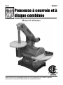
Manuel d'utilisateur
Ponceuse à courroie et à
disque combinée

9009697 Ponceuse à courroie et à disque combinée V 4,0
2 En cas de questions techniques, appelez le 1-800-665-8685
SPÉCIFICATIONS
Taille de roue 5 po
Taille de la courroie
1 x 30 po
Horsepower 1/3 CV
Tension nominale 120 V c.c.
Courant nominal 2,3 A
Fréquence nominale 60 Hz
Vitesse à vide
3 450 tr/min
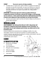
INTRODUCTION
Ensemble de ponçage polyvalent et puissant qui convient à tous les dessus
d’établi. Comprend un puissant moteur à induction de 1/3 CV, un interrupteur
résistant à la poussière, une table de travail en aluminium réglable et un guide. Le
cadre en aluminium léger et la base de tôle facilitent son transport. Disque abrasif
à grain 80 standard et courroie compris. Dispositif d'arrêt arrière de courroie
amovible pour polir et éliminer la rouille des pièces à travailler qui sont
recourbées. Panneau latéral amovible avec bouton de verrouillage permettant de
remplacer rapidement la courroie. Bouton de commande du centrage de courroie
afin de faciliter son réglage. Les goulottes d'évacuation arrière et latérale
s'accrochent aux systèmes de collecte de poussière afin de faciliter le nettoyage.
SÉCURITÉ
AVERTISSEMENT ! Veuillez lire et comprendre toutes les instructions avant
d'utiliser cet outil. L'utilisateur doit respecter les précautions de base
lorsqu'il utilise cet outil afin de réduire le risque de blessure ou de
dommage à l'équipement.
Ponceuse à courroie et à
disque combinée
La page est en cours de chargement...
La page est en cours de chargement...
La page est en cours de chargement...
La page est en cours de chargement...
La page est en cours de chargement...
La page est en cours de chargement...
La page est en cours de chargement...
La page est en cours de chargement...
La page est en cours de chargement...
La page est en cours de chargement...
La page est en cours de chargement...
La page est en cours de chargement...
La page est en cours de chargement...
La page est en cours de chargement...
La page est en cours de chargement...
La page est en cours de chargement...
-
 1
1
-
 2
2
-
 3
3
-
 4
4
-
 5
5
-
 6
6
-
 7
7
-
 8
8
-
 9
9
-
 10
10
-
 11
11
-
 12
12
-
 13
13
-
 14
14
-
 15
15
-
 16
16
-
 17
17
-
 18
18
-
 19
19
-
 20
20
-
 21
21
-
 22
22
-
 23
23
-
 24
24
-
 25
25
-
 26
26
-
 27
27
-
 28
28
-
 29
29
-
 30
30
-
 31
31
-
 32
32
-
 33
33
-
 34
34
-
 35
35
-
 36
36


Powerfist 9009697 Le manuel du propriétaire
- Catégorie
- Ponceuses électriques
- Taper
- Le manuel du propriétaire
dans d''autres langues
- English: Powerfist 9009697 Owner's manual
Documents connexes
Autres documents
-
PROPOINT 9027988 Le manuel du propriétaire
-
Power Fist 8726788 Le manuel du propriétaire
-
-
General International BD7004 Manuel utilisateur
-
Skil 3375-01 Manuel utilisateur
-
Delta SA180 Mode d'emploi
-
Ryobi BD4601G Le manuel du propriétaire
-
Power Fist 12 in. Electric Concrete Saw Manuel utilisateur