
Manual No. 181702
Rev G. 1/14/13
ECN13-011
5 1/2” x 8 1/2” Booklet
Do Not Return This Backpack To The Store
For Help, Information or Parts, Call : 1-800-311-9903
The Fountainhead Group, Inc.
23 Garden St., New York Mills, NY 13417
1-800-311-9903
www.TheFountainheadGroup.com
CAUTION: Read and follow all instructions
BACKPACK
SPRAYER
Backpack Sprayer
Use and Care Manual

Page 2
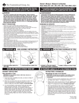
Do not return sprayer to store, if you experience problems or have questions contact
our toll free Customer Service Center, M-F 8AM - 5PM, EST, at 1-800-311-9903, or
e-mail: [email protected]om, or access online at: www.TheFountainheadGroup.com.
SAFETY PRECAUTIONS
• Read owner’s manual completely before operating this sprayer.
• Always use goggles, gloves, and protective clothing when using sprayer.
• Read and follow all instructions and cautions on label of products used in this sprayer.
• Never use ammable liquids, caustics, acids, or hot water in this tank.
• Do not leave sprayer in the sun when not in use.
• Spray when air is calm to prevent drift of chemicals.
• Do not use sprayer near open ame or anything that could cause ignition of the spray.
• Always inspect hose and all hose connections before each use. A damaged hose, or loose hose
connection can result in unintended exposure to the pressurized chemical, resulting in serious injury or
property damage.
• Do not lift or carry sprayer by the hose, shut-o valve, or wand extension. Carry by the handle only.
• Do not pressurize with any mechanical device such as an air compressor, since this can create a
dangerous pressure level and bursting of parts resulting in serious injury. Only use original pump.
• Do not store chemicals in this tank.
• Always release pressure when sprayer is not in use and before performing any maintenance.
• Clean and rinse sprayer thoroughly after each use.
• Never attempt to alter sprayer from original condition.
• Always use replacement parts from original manufacturer.
• Keep the sprayer and all chemicals out of the reach of children.
WARNING
The sprayer is operated with liquid under pressure. Failure to observe caution and to follow instructions for
operating and cleaning can cause tank, hose and other parts to be weakened and rupture under pressure.
This can result in serious injury from high pressure discharge of liquids or forcible ejection of parts. Do not
use ammable materials in this sprayer. Material could ignite or explode, causing serious injury and/or
possible death. For safe use of this product, you must read and follow all instructions before use.
TEST SPRAYER WITH WATER BEFORE USING ANY CHEMICALS.
CAUTION
Always empty, clean and dry tank, pump system, shut-o, hose, and extension after each use. FAILURE TO
DO SO MAY WEAKEN SPRAYER COMPONENTS, CAUSING COMPONENTS TO RUPTURE WHEN PRESSURIZED.
Additionally, FAILURE TO CLEAN AND PROPERLY MAINTAIN YOUR SPRAYER WILL VOID MANUFACTURER’S
WARRANTY.
WARNING
ALWAYS CLEAN THE SPRAYER AND SHUT-OFF THOROUGHLY AFTER EACH USE OR WHEN
CHANGING APPLICATIONS AS DESCRIBED IN THE CLEANING SECTION. FAILURE TO
COMPLETELY CLEAN MAY CAUSE CROSS-CONTAMINATION.

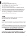
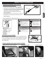
ASSEMBLY INSTRUCTIONS
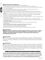
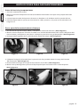
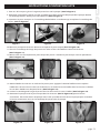
Assemble Pump Handle
Slide handle onto shaft and line up holes. Thread bolt through handle
and shaft and securely tighten. Thread on lock nut and tighten using
a 13mm (or adjustable) wrench. Handle can be mounted on left or
right depending on user preference. (See Figure D)
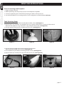
Assemble Extension, Shut-O, Nozzle and Spray
Optimizer
1. Install the extension “wand” onto the shut-o
assembly and tighten the nut securely. (See Figure A)
2. (Optional) Install Spray Optimizer for low pressure (low
drift) applications. This will help prevent weed killer
formulas from drifting into undesired areas. (Do not
over tighten, actual position will vary. See Figure B)
3. Install selected nozzle onto the end of the extension
or optimizer (if installed) and tighten securely.
(See Figure C)
Figure A
Figure B
(Optional)
Figure C
Figure D
Folding Handle (included on some models)
1. Thread bolt through handle
and shaft as stated above.
2. Snap strap around
handle.
3. Handle shown in
folded position.
Page 3
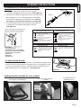
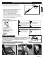
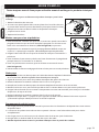
SELECT USING NOZZLE CHART BELOW
(Nozzle selections vary by model)
A. Cap Nut
B. Foaming Nozzle
C. Red High-Volume Fan Nozzle
D. Yellow Low-Volume Fan Nozzle
E. Adjustable Cone Nozzle
F. Flat Seal
G. Adapter
H. Extension
E
A
G
B
C
F
H
D
ADJUSTABLE CONE USES:
Spot spraying in or around flower
beds, trees, and shrubs.
Edging along fences, driveways,
and walkways.
Killing brush such as poison ivy,
poison oak, kudzu and wild
blackberry.
Preparing garden beds for planting
of ornamentals and vegetables.
For precision spraying in confined
areas such as gardens and flower
beds.
FAN NOZZLE USES:
Lawn replacement. Kill lawn and
weeds before planting a new lawn.
Preparing large areas for planting
of ornamental and vegetable
gardens.
RED HIGH VOLUME YELLOW LOW VOLUME
FAN NOZZLE USES:
FOAMING NOZZLE USES:
Spot spraying in flower beds,
walkways, driveways, and patios,
around trees and shrubs.
Edging along fences, driveways and
walkways.
Killing brush such as poison ivy,
poison oak, kudzu and wild
blackberry.

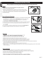
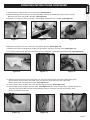
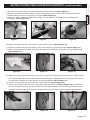
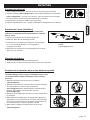
Pressurizing and Spraying
1. To begin pressurizing, be sure shut-o lever is not depressed. Pump handle
up and down in a smooth motion (See Figure E). Operating pressure is
reached when pumping becomes dicult, which is no more than
5-7 full pumps. (Do not over-pressurize)
2. Direct nozzle away from you and squeeze shut-o lever to begin spraying.
3. To maintain pressure while spraying, operate pump handle every 8 sec.
or as needed.
4. For continuous spraying, squeeze lever and rotate lock. (See Figure F)
5. Unlock if needed and release shut-o lever to stop spraying.
page 4
Cleaning
1. Fill the tank with cool, clean tap water. Replace the cap and
tighten securely. (Never use hot water for cleaning)
2. Agitate the tank to rinse the chemical from the tank walls.
3. Remove the cap and empty the contents into gravel or bare soil.
4. Rell the tank with clean tap water. Replace the cap and tighten securely.
5. Pressurize the tank as described in the Pressurizing and Spraying section.
6. Direct the nozzle away from you and activate the shut-o for at least 30 seconds to clean the
pressure chamber, hose and shut-o.
7. Remove the cap and empty the contents into gravel or bare soil.
8. Repeat steps 4 - 7 until thoroughly cleaned. Remove nozzle when ushing pump system. Clean nozzle
before replacing.
Always conduct a test using cool, clean water before mixing chemicals.
OPERATING INSTRUCTIONS
Filling
Always refer to chemical manufacturer for proper mixture.
1. Remove the cap from the tank.
2. Make sure the lter basket is in place in the neck of the tank. The
lter basket includes the seal and must be in place to prevent leaks.
3. Fill the tank with cool water and chemical to the desired level.
4. Reinstall the cap.
Figure E
Figure F
Sprayer Storage
1. Never store sprayer with pressure in chamber or liquid in any part of sprayer.
2. Sprayer tank should be hung upside down, with the cap removed, to dry completely.
3. Do not store or leave any solution in the tank after use.
4. Store in a warm, dry location out of direct sunlight.
5. Keep the sprayer and all chemicals out of the reach of children.
LEVER

Always conduct a test using cool, clean water before mixing chemicals.
Page 5
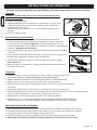
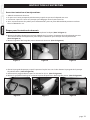
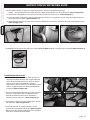
MAINTENANCE
Tank Maintenance
1. After each use, rinse the tank with cool, clean water.
2. Check the check valve (See Figure G) and lter basket gasket. (See Figure H)
Make sure they do not show signs of wear and are operating properly.
Replace them as required.
3. Clean any dirt or debris from the lter basket.
4. Periodically check the straps for fraying.
Replace them as required.
Figure G Figure H
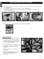
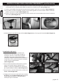
Pressure Chamber Maintenance
WARNING: Always depressurize sprayer before
cleaning or replacing pressure chamber by activating
shut-o and spraying out all pressure.
1. Remove the tank cap and strainer (See Figure I).
2. Reach into the tank and turn the chamber 1/4 turn
counterclockwise (See Figure J) to unlock the chamber
from the pump then remove chamber from tank
(See Figure K).
3. Rinse out any debris that may have accumulated in
the chamber.
4. Reinstall the chamber into the pump by aligning the
tabs on the chamber with the slots in the pump, push
rmly into pump and turn clockwise until pump stops.
5. Reinstall the strainer and tank cap (See Figure L).
AB
C
A. Handle
B. Filter
C. Shut-o Assembly
Shut-o Maintenance (Smith Pro)
Always depressurize sprayer before maintenance
by activating shut-o and spraying contents out.
1. Unscrew the handle from the shut-o assembly.
2. Remove the lter from the shut-o assembly.
3. Clean any debris from inside the handle,
shut-o assembly, or the lter by rinsing with
cool, clean water.
4. Reassemble the components as shown and
tighten all connections securely.
AB
C
Nozzle Maintenance
1. If nozzle clogs, remove and disassemble the nozzle assembly.
2. Clean the openings of any obstructions and reassemble.
Figure L
Figure I
Figure K
Figure J
Clockwise
Counter-Clockwise

page 6
SERVICING INSTRUCTIONS
Tank Servicing Steps
1. Unscrew cap from tank. Remove and replace check valve. (See Figure 1)
2. Remove pressure chamber as outlined in Pressure Chamber Maintenance section of the manual.
Remove and replace o-ring. Lubricate o-ring with petroleum jelly. (See Figure 2)
3. Unsnap agitator from piston rod. Remove from tank. (See Figure 3)
Figure 3
Figure 2
Figure 1
4. Position pump handle to the furthest downward position.
Remove pump handle from sprayer. (See Figure 4)
5. Disassemble carry handle by removing the (6) screws. (See Figure 5)
6. Remove hitch pin and lift pivot clip o of the piston rod. (See Figure 6)
Figure 6
Figure 4 Figure 5
Prior to servicing and/or repairs.
1. Empty contents of tank.
2. While squeezing shut-o, pump sprayer until all liquid is expelled.
3. Continue squeezing shut-o without pumping to release all air pressure.
4. You will nd all parts for servicing primary seals and gaskets to be included in KIT #32.

SERVICING INSTRUCTIONS CONTINUED
7. Pull upward to slide piston rod out of pump. (See Figure 7)
8. While holding onto the pump, use an adjustable wrench to unthread pump nut from pump.
Remove nut, hose and barb assembly. (See Figure 8)
9. Inspect (2) o-rings on barb assembly. If damaged, replace hose assembly. (See Figure 9)
Figure 9
Figure 8
Figure 7
page 7
Figure 10 Figure 11 Figure 12
10. Remove pump out of tank. Remove and replace gasket. (See Figure 10)
11. Slide piston rod assembly down and out of grommet and remove from tank. (See Figure 11)
12. Carefully remove and replace o-ring from piston. Lubricate o-ring with petroleum jelly. (See Figure 12)
Figure 13 Figure 14 Figure 15
13. Remove grommet from tank using pliers to grasp the head of the grommet while exing the
grommet out of the hole in the tank. Press or tap new grommet into tank. Lubricate
hole in grommet with petroleum jelly. (See Figure 13)
14. Insert piston rod assembly into tank and through grommet. (See Figure 14)
15. Reassemble pump with gasket into tank. (See Figure 15) for correct orientation. Tighten pump nut
securely with adjustable wrench while holding pump to maintain correct orientation. Push
piston assembly into pump.

SERVICING INSTRUCTIONS CONTINUED
page 8
16. Attach pivot clip to piston rod and insert hitch pin. Note orientation of piston rod must match the pivot
clip. (See Figure 16)
17. Reassemble carry handle onto tank. Tighten all (6) screws. (See Figure 5)
18. To reinstall the agitator, line the notch up on the agitator with the swedge on piston rod and snap
into place. (See Figure 17)
19. Reinstall pressure chamber as outlined in the Pressure Chamber Maintenance section. (See Figure 18)
Figure 16 Figure 17 Figure 18
Harness Installation
1. For each side, remove the small plastic clips
from the two shoulder strap loops and thread
each loop through the slots at the top of the
carry handle. Replace the clips through the
loops and pull strap securing the two shoulder
straps in place. (See Figure 20)
2. To install lower end of the straps, remove strap
from top portion of buckles and place around
the foot stand, starting from underneath.
(See Figure 21)
3. Loop strap through the rst section of buckle.
(See Figure 22)
4. Next loop strap through other section of buckle
and tighten (See Figure 23). Adjust the
shoulder pads and strap length for a
comfortable t.
Figure 23Figure 22
Figure 21
Figure 20
Figure 19
20. Replace tank cap, lter (See FIgure 19) and pump handle (See Figure 4).

page 9
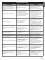
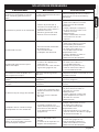
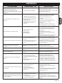
TROUBLESHOOTING
TROUBLE LOOK FOR REMEDY
Sprayer starts to spray when
pumping or sprayer will not stop
spraying when shut-o lever is
released.
Shut-o lock is engaged.
Squeeze shut-o lever and
disengage the lock. See
Pressurizing and Spraying section.
Sprayer will not build pressure.
1. Pressure chamber (#2)
i n s t a l l e d i n t o p u m p ( # 3 ) .
2. Dirty, damaged or worn pump
o r c h a m b e r o - r i n g ( # 3 2 A ) .
3. Dirty poppet in pump.
1. Install pressure chamber as
described in Pressure
Chamber Maintenance section.
2. Clean and lubricate or
replace o-rings as described
in Servicing section.
3. Clean sprayer as described in
Cleaning section.
Sprayer will not spray.
1 . S p r a y e r p r e s s u r i z a t ion .
2. Shut-o clogged.
3. Nozzle clogged.
1. Pressurize sprayer as described
in Pressurizing and Spraying
section.
2. Clean shut-o as described in
Shut-o Maintenance section.
3. Clean nozzle as described in
Nozzle Maintenance section.
Sprayer leaks from the bottom of
the tank.
1. Loose pump nut (#16).
2. Damaged or worn o-rings or
seals (kit #32).
1. Tighten pump nut as described
in Servicing section.
2. Replace o-rings and seals as
described in Servicing
section.
Sprayer leaks where piston rod
enters top of the tank.
Dirty, damaged, or worn
grommet (#32C).
Clean and lubricate hole in grom-
met or replace grommet as de-
scribed in Servicing section.
Hose leaks at tank connection. Cracked, swollen or faulty hose. Replace shut-o assembly.
Hose leaks at shut-o. Cracked, swollen or faulty hose. Replace shut-o assembly.
Pump handle is dicult to operate.
1. Swollen or damaged pump
piston o-ring (#32D).
2. Dirty, dry or damaged
grommet (#32C).
1. Clean and lubricate or replace
o-ring as described in
Servicing section.
2. Clean and lubricate hole in
grommet or replace grommet
as described in Servicing
section.
Nozzle drips when shut-o lever is
released.
1. Dirt or debris in shut-o valve.
2. Damaged o-ring or seal in
shut-o (kit #31).
1. Clean shut-o as described in
Shut-o Maintenance section.
2. Service shut-o seals as
described in Maintenance
service kit #31.
Nozzle tip leaks, poor spray
pattern, partial spray or complete
stoppage.
1. Flat seal is missing or
damaged.
2. Spray extension or nozzle
clogged.
1. Replace at seal at extension
tip (kit #31).
2. Remove nozzle and clean as
described in Nozzle
Maintenance section.

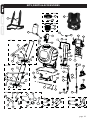
31A
13
14
31B
31C
31D
31E
31F
32E 32D
32C
32B
32A
34F
34E
34D
34C
34B
34A
33F
33E
33D
33C
33B
33A
12
35
KIT #27
KIT #28
KIT #29
KIT #31
KIT #34
KIT #33
KIT #32
KIT #30
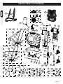
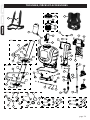
KITS, PARTS & ACCESSORIES
page 10
2
1
1-SS
3
4
5
6
7
8
9
10 11
15
15-SS
16
17
18
18
19
20
21
22
26
23
24
25
27A
27B
28B
28A
29A
29B
29C
29D
29E
29F
29G
29H
29I
30A
30B
30C
30D
30E
30F
30G
30H
30I
30J
32A
32B
32C
32D
31A
31B
31C
31D
31E

page 11
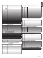
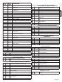
KEY# PART# DESCRIPTION
1 181700 TANK ASSEMBLY
1-SS 182104 TANK ASSEMBLY, STAINLESS STEEL
2 182008 HIGH CAPACITY RESERVOIR / CHAMBER
ASSEMBLY
3 182070 PUMP
4 181635 DRIVE SUPPORT SHROUD
5 181653 LEFT BUSHING
6 181654 RIGHT BUSHING
7 181954 DRIVE LEVER ASSEMBLY
8 181669 PUMP PISTON ASSEMBLY
9 181665 STANDARD AGITATOR
10 181641 PIVOT CLIP
11 181648 BACK HANDLE
12 181826 PRESSURE REGULATOR (25 PSI)
13 181659 SHOULDER HARNESS (STANDARD)
14 181889 SHOULDER HARNESS (DELUXE)
15 181824 21” WAND ASSEMBLY
15-SS 182112 21” WAND ASSEMBLY, STAINLESS STEEL
16 181925 SHUT-OFF ASSEMBLY, SMITH PRO
(BACKPACK VER.)
17 181649 SHROUD ROD
18 181529 SCREW, UPPER HANDLE (4) & SHROUD (2)
19 181716 SCREW, LOWER HANDLE (2)
20 182017 DRIVE LEVER BOLT (2)
21 181906 DRIVE LEVER FLAT WASHER (2)
22 181757 LOCK NUT (2)
23 181651 SHROUD SCREW (2)
24 181684 SHROUD WASHER (2)
25 181650 SHROUD SPACER (2)
26 181673 HITCH PIN
KIT #29 181788 BOLT-ON PUMP HANDLE KIT
(STANDARD)
29A 181922 STANDARD PUMP HANDLE ASSEMBLY
(GRIP INCLUDED)
29B 181753 BOLT-ON DRIVE SHAFT
29C 181756 HEX BOLT
29D 181757 LOCK NUT
29E 181954 DRIVE LEVER ASSEMBLY
29F 182021 DRIVE LEVER BOLT, 40mm (2)
29G 181906 DRIVE LEVER FLAT WASHER (2)
29H 181908 DRIVE LEVER LOCK WASHER (2)
29I181907 DRIVE LEVER NUT (2)
28A 181445 FILTER BASKET GASKET
28B 181519 FILTER BASKET
KIT #28 181564 FILTER BASKET ASSEMBLY KIT
27A 181444 TANK CAP
27B 171015 CHECK VALVE
KIT #27 181446 CAP ASSEMBLY KIT
30A 181923 FOLDING PUMP HANDLE ASSEMBLY
(GRIP INCLUDED)
30B 181753 BOLT-ON DRIVE SHAFT
30C 181756 HEX BOLT
30D 181757 LOCK NUT
30E 181772 RETAINER STRAP
30F 181954 DRIVE LEVER ASSEMBLY
30G 182021 DRIVE LEVER BOLT, 40mm (2)
30H 181906 DRIVE LEVER FLAT WASHER (2)
30I181908 DRIVE LEVER LOCK WASHER (2)
30J 181907 DRIVE LEVER NUT (2)
KIT #30 181789 BOLT-ON PUMP HANDLE KIT
(FOLDING)
KIT #31 181910 SMITH PRO SHUT-OFF SERVICE
KIT
31A 181840 POPPET SEAL
31B 181493 VALVE BODY O-RING
31C 181468 FILTER
31D 181812 FLAT NOZZLE SEAL (2)
31E 181810 WAND O-RING
31F 181805 ADJUSTABLE NOZZLE O-RING
KIT #32 181909 BACKPACK SERVICE KIT
32A 171488V RESERVOIR / CHAMBER O-RING
32B 171740 PUMP GASKET
32C 181668 TANK GROMMET
32D 171487V PISTON O-RING
32E 171015 CHECK VALVE
KIT #33 181869 POLY NOZZLE KIT
33A 181822 POLY ADJUSTABLE NOZZLE
33B 180168 YELLOW FLAT FAN NOZZLE (LOW VOLUME)
33C 180097 RED FLAT FAN NOZZLE (HIGH VOLUME)
33D 180266 FOAMING NOZZLE
33E 181812 FLAT NOZZLE SEAL
33F 181804 NOZZLE CAP NUT
KIT #34 181870 BRASS NOZZLE KIT
34A 181823 BRASS ADJUSTABLE NOZZLE
34B 180168 YELLOW FLAT FAN NOZZLE (LOW VOLUME)
34C 180097 RED FLAT FAN NOZZLE (HIGH VOLUME)
34D 180266 FOAMING NOZZLE
34E 181812 FLAT NOZZLE SEAL
34F 181804 NOZZLE CAP NUT
KIT #35 181825 14 PSI PRESSURE REGULATOR KIT
35 181825 14 PSI PRESSURE REGULATOR ASSEMBLY

SERVICE KITS, PARTS & ACCESSORIES ARE AVAILABLE BY CONTACTING
The Fountainhead Group, Inc. - Customer Service Center
Monday - Friday 8 a.m. - 5 p.m., EST
Toll Free: 1-800-311-9903
or
e-mail: [email protected]
or
Access online at: www.TheFountainheadGroup.com
page 12

Atomizador de Mochila
Manual No. 181702
Rev G. 1/14/13
ECN13-011
No devuelva este atomizador a la tienda
Para obtener ayuda, información o piezas, llame al:
1-800-311-9903
The Fountainhead Group, Inc.
23 Garden St., New York Mills, NY 13417
1-800-311-9903
www.TheFountainheadGroup.com
PRECAUCIÓN: Lea y siga todas las instrucciones
ATOMIZADOR
DE
MOCHILA
Manual de uso y cuidado

PRECAUCIONES DE SEGURIDAD
• Lea todo el manual del usuario antes de operar este atomizador.
• Siempre utilice gafas de seguridad, guantes y ropa protectora cuando use el atomizador.
• Lea y siga todas las instrucciones y precauciones que se muestran en la etiqueta de los productos que se
usan en este atomizador.
• Nunca utilice líquidos inamables, agentes cáusticos, ácidos o agua caliente en este tanque.
• No deje el atomizador expuesto al sol cuando no esté en uso.
• Utilice el atomizador cuando no haya viento para evitar el desplazamiento de sustancias químicas.
• No use el atomizador cerca de llamas o agentes que pudieran ocasionar que se encienda la solución de
rociado.
• Siempre revise la manguera y todas las conexiones de la misma antes de cada uso. Una manguera
dañada o una con exión suelta pueden ocasionar una exposición no deseada a la sustancia química
presurizada, lo cual podría provocar lesiones graves o daños a la propiedad.
• No levante ni transporte el atomizador por la manguera, la válvula de cierre o la varilla de extensión. Sólo
transpórtelo por el mango.
• No presurice con ningún dispositivo mecánico, como un compresor de aire, ya que puede generar
niveles de presión peligrosos y algunas piezas podrían estallar, lo cual ocasionaría lesiones graves. Sólo
use la bomba original.
• No almacene sustancias químicas en este tanque.
• Siempre libere la presión cuando el atomizador no esté en uso y antes de hacer cualquier
mantenimiento.
• Limpie y enjuague el atomizador completamente después de cada uso.
• Nunca intente modicar la condición original del atomizador.
• Siempre utilice las piezas de reemplazo del fabricante original.
• Mantenga el atomizador y todas las sustancias químicas fuera del alcance de los niños.
PRECAUCIÓN:
Siempre vacíe, limpie y seque el tanque, el sistema de bomba, cierre, manguera y extensión después de
cada uso. Si no lo hace, los componentes del atomizador podrían deteriorarse y romperse cuando estén
presurizados. Si no limpia el atomizador y no le da un mantenimiento adecuado, se cancelará la garantía
del fabricante.
ADVERTENCIA
El atomizador funciona con líquido a presión. Si no lo maneja con cuidado o no sigue las instrucciones de
operación y limpieza, podría ocasionar el deterioro o la ruptura del tanque, manguera y otras piezas que
están bajo presión. Esto puede provocar lesiones graves debido a la descarga de líquidos a alta presión o
a la expulsión forzada de las piezas. No use materiales inamables en este atomizador. El material podría
encenderse o explotar y provocar lesiones graves y/o muerte. Para usar este producto de manera segura,
debe leer y seguir todas las instrucciones antes de usarlo.
PRUEBE EL ATOMIZADOR CON AGUA ANTES DE USAR SUSTANCIAS QUÍMICAS.
página 14
No devuelva el atomizador a la tienda, si tiene problemas o preguntas, comuníquese
con nuestro Centro de servicio al cliente llamando a la línea gratuita 1-800-311-9903,
de lunes a viernes de 8 a.m. a 5 p.m., hora del este, escribiendo por correo electrónico
a: [email protected]om o accediendo en línea a: www.TheFountainheadGroup.com.
ADVERTENCIA
SIEMPRE LIMPIE EL ROCIADOR Y CIERRELO BIEN DESPUÉS DE CADA USO O CUANDO
CAMBIE LAS APLICACIONES COMO SE DESCRIBE EN LA SECCIÓN LIMPIEZA. EL NO
CUMPLIR CON LIMPIAR COMPLETAMENTE EL ROCIADOR PODRÍA PROVOCAR
CONTAMINACIÓN CRUZADA.

Figura A
Figura B
(Opcional)
Figura C
INSTRUCCIONES DEL ENSAMBLAJE
SELECCIONE UTILIZANDO LA TABLA DE BOQUILLAS QUE SE
MUESTRA A CONTINUACIÓN.
(Las selecciones de boquilla varían por modelo)
A. Tuerca ciega
B. Boquilla para espuma
C. Boquilla roja con ventilador
para alto volumen
D. Boquilla amarilla con ventilador
para bajo volumen
E. Boquilla de cono adjustable
F. Sello plano
G. Adaptador
H. Extensión
Ensamblado de la extensión, el cierre,
la boquilla y el optimizador de rociado
1. Instale la “varilla” de extensión en el
dispositivo de cierre y ajuste la tuerca
hasta que esté segura. (Vea la Figura A)
2. (Opcional) Instale el Optimizador de Rociado para
aplicaciones de baja presión (ujo bajo).
Esto ayudará a evitar que las fórmulas para
matar la maleza se desplacen hacia áreas
indeseadas. (No apriete demasiado,
la posición real puede variar. Vea la Figura B)
3. Instale la boquilla seleccionada en el extremo de la
extensión u optimizador (si está instalado) y ajuste la
tuerca rmemente. (Vea la Figura C)
Monte el mango de la bomba
Deslice el mango hacia el eje y alinee los oricios. Pase el tornillo através
del mango y el eje y ajuste rmemente. Enrosque la tuerca debloqueo y
ajústela usando una llave de 13 mm (o ajustable). Se puede jar el mango
al lado derecho o al lado izquierdo dependiendo de lo que el usuario
preera. (Vea la Figura D)
Figura D
Mango plegable (incluido en algunos modelos)
1. Pase el tornillo a través del mango y el
eje como se indicó anteriormente.
2. Inserte la correa
alrededor del mango.
3. El mango se muestra
en posición doblada.
página 15
Usos de las boquillas cono ajustables:
Rociado localizado en o alrededor de
arriates, árboles o arbustos.
Bordes a lo largo de cercas, entradas
y caminos.
Destrucción de malezas, por ejemplo,
hiedra venenosa, roble venenosa,
kudzu y zarzamora silvestre
Preparación de arriates de jardín para
sembrar plantas ornamentales y
vegetales.
Para un rocío de precisión en
zonas confinadas tales como
jardines y maceteros.
ventilador para alto volumen:
Reemplazo de césped. Mate el
césped y las malezas antes de
sembrar el césped nuevo.
Preparación de áreas grandes
para el sembrado de plantas
ornamentales y vegetales.
Usos de las boquillas roja con Usos de las boquillas amarilla con
ventilador para bajo volumen:
Usos de las boquillas espumantes:
Rociado localizado de arriates,
caminos, entradas y patios,
alrededor de árboles y arbustos.
Bordes a lo largo de cercas,
entradas y caminos.
Destrucción de malezas, por
ejemplo, hiedra venenosa, roble
venenoso, kudzu y zarzamora
silvestre.
E
A
G
B
C
F
H
D

página 16
Limpieza
1. Llene el tanque con agua de grifo fresca y limpia. Vuelva a colocar la tapa hasta
que quede asegurada. (Nunca utilice agua caliente para limpiar)
2. Agite el tanque para limpiar la sustancia química de las paredes del tanque.
3. Retire la tapa y vacíe el contenido en gravilla o en suelo descubierto.
4. Rellene el tanque con agua de grifo limpia. Vuelva a colocar la tapa hasta que quede
asegurada.
5. Presurice el tanque como se describe en la sección Presurización y atomización.
6. Dirija la boquilla lejos de usted y active el dispositivo de cierre durante por lo menos 30 segundos para
limpiar la cámara de presión, la manguera y el dispositivo de cierre.
7. Retire la tapa y vacíe el contenido en gravilla o en suelo descubierto.
8. Repita los pasos 4 a 7 hasta que la unidad esté completamente limpia. Retire la boquilla
cuando enjuague el sistema de la bomba. Limpie la boquilla antes de volver a colocarla.
Siempre realice una prueba con agua limpia y fría antes de mezclar sustancias químicas.
Presurización y atomización
1. Para empezar a presurizar, asegúrese de que el gatillo de cierre no
esté presionado. Mueva el mango de la bomba hacia arriba y abajo con
un movimiento suave (Vea la Figura E). La presión operativa se alcanza
cuando el bombeado se torna difícil, el cual no es a más de 5 a 7 bombeadas
completas. (No presurice en exceso)
2. Dirija la boquilla lejos de usted y presione la palanca de cierre para empezar
a atomizar.
3. Para mantener la presión mientras atomiza, haga funcionar el mango de la
bomba cada 8 segundos o según lo que sea necesario.
4. Para atomizar de forma continua, presione la palanca y gire el seguro.
(Vea la Figura F)
5. Retire el seguro si es necesario y suelte la palanca del dispositivo de cierre
para dejar de atomizar.
Figura E
Figura F
Almacenamiento del atomizador
1. Nunca guarde el atomizador con la cámara presurizada o con líquido en ninguna de sus piezas.
2. El tanque del atomizador debe colgarse boca abajo y sin la tapa para que seque por completo.
3. No guarde ni deje solución en el tanque después de usarlo.
4. Guarde la unidad en un lugar templado y seco, fuera del alcance de la luz solar directa.
5. Mantenga el atomizador y todas las sustancias químicas fuera del alcance de los niños.
INSTRUCCIONES DE OPERACIÓN
Llenado
(Siempre consulte al fabricante de la sustancia química para saber
la mezcla correcta).
1. Quite la tapa del tanque.
2. Asegúrese de que la canasta del ltro se encuentre en su lugar en el
cuello del tanque. La canasta de ltro incluye el sello y debe estar
instalada para evitar fugas.
3. Llene el tanque con agua fría y la sustancia química hasta el nivel
deseado.
4. Vuelva a colocar la tapa.
PALANCA

página 17
MANTENIMIENTO
Mantenimiento del tanque
1. Después de cada uso, enjuague el tanque con agua limpia y fría.
2. Revise la válvula de retención (Vea la Figura G) y la junta de la canasta del
ltro (Vea la Figura H). Asegúrese de que no presenten señales de desgaste
y que estén funcionando correctamente. Reemplácelas si es necesario.
3. Limpie cualquier suciedad o residuo de la canasta del ltro.
4. Revise periódicamente las correas para ver si existe algún desgaste. Reemplácelas si es necesario.
Figura G Figura H
Mantenimiento de la cámara de presión de alta
capacidad
ADVERTENCIA: siempre despresurice el atomizador
antes de limpiarlo o reemplazar la cámara de presión
activando el dispositivo de cierre y atomizando toda la
presión hacia afuera.
1. Retire la tapa del tanque y el colador (Vea la Figura I).
2. Dentro del tanque, localice y gire la cámara 1/4 de vuelta
hacia la izquierda (Vea la Figura J) para aojarla de la
bomba y luego retire la cámara del tanque
(Vea la Figura K).
3. Enjuague cualquier residuo que se haya podido
acumular en la cámara.
4. Vuelva a instalar la cámara en la bomba alineando las
lengüetas de la cámara con las ranuras de la bomba,
empuje con rmeza hacia la bomba y gire hacia la
derecha hasta que la bomba se detenga.
5. Vuelva a instalar el colador y la tapa del tanque
(Vea la Figura L).
Mantenimiento del dispositivo de cierre (Smith Pro)
Siempre despresurice el atomizador antes de darle
mantenimiento al activar el cierre y atomizar los
contenidos hacia afuera.
1. Destornille el mango del dispositivo de cierre.
2. Retire el ltro del dispositivo de cierre.
3. Limpie todo residuo presente en el interior del
mango y del dispositivo de cierre o en el asiento
de válvula o ltro.
4. Vuelva a ensamblar los componentes según se muestra en
la gura y apriete todas las conexiones hasta que queden
aseguradas.
AB
C
A. Mango
B. Filtro
C. Dispositivo de cierre
Mantenimiento de la boquilla
1. Si la boquilla se atasca, retírela y desarme el ensamblaje de la boquilla.
2. Retire todas las obstrucciones presentes en las aberturas y vuelva a ensamblar.
AB
C
Figura L
Figura I
Figura K
Figura J
Derecha
Izquierda

INSTRUCCIONES PARA DAR MANTENIMIENTO
Pasos para darle mantenimiento al tanque
1. Desatornille la tapa del tanque. Retire y reemplace la válvula de retención. (Vea la Figura 1)
2. Retire la cámara de presión tal como se indica en la sección Mantenimiento de la cámara de presión del
manual. Retire y reemplace la junta tórica. Lubrique la junta tórica con gel de petróleo. (Vea la Figura 2)
3. Desenganche el agitador de la varilla de pistón. Retire del tanque. (Vea la Figura 3)
Figura 3
Figura 2
Figura 1
4. Coloque el mango de la bomba hacia la posición más baja posible. Retire el mango de la bomba
del atomizador. (Vea la Figura 4)
5. Desensamble el mango de transporte retirando los (6) tornillos. (Vea la Figura 5)
6. Retire la clavija de enganche y levante el clip de pivote que se encuentra en la varilla de pistón.
(Vea la Figura 6)
Figura 6
Figura 4 Figura 5
Antes del servicio y/o reparaciones.
1. Vacíe el contenido del tanque.
2. Mientras presiona el dispositivo de cierre, bombee el atomizador hasta que se haya expulsado todo
el líquido.
3. Continúe presionando el dispositivo de cierre sin bombear a n de liberar toda la presión del aire.
4. Descubrirá que todas las partes para mantener los sellos primarios y las juntas están incluidas en el
Juego No. 32.
página 18

página 19
INSTRUCCIONES PARA DAR MANTENIMIENTO (continuación)
7. Jale hacia arriba para retirar la varilla de pistón fuera de la bomba. (Vea la Figura 7)
8. Mientras sostiene la bomba, utilice una llave ajustable para retirar la tuerca de la bomba fuera de la
bomba. Retire la tuerca, la manguera y la espiga. (Vea la Figura 8)
9. Revise (2) anillos O del ensamblaje de la espiga. Si están dañados, reemplace el ensamblaje de la
manguera. (Vea la Figura 9)
Figura 9
Figura 8
Figura 7
Figura 10 Figura 11 Figura 12
10. Retire la bomba fuera del tanque. Retire y reemplace la junta. (Vea la Figura 10)
11. Deslice la varilla de pistón hacia abajo y hacia afuera del ojal y retire del tanque. (Vea la Figura 11)
12. Retire y reemplace con cuidado la junta tórica del pistón. Lubrique la junta tórica con gel de petróleo.
(Vea la Figura 12)
Figura 13 Figura 14 Figura 15
13. Retire el ojal del tanque utilizando un alicate para agarrar la cabeza del ojal mientras lo va exionando
para retirarlo del oricio del tanque. Presione o dé pequeños golpecitos para que el ojal nuevo encaje
en el tanque. Lubrique el oricio del ojal con gel de petróleo. (Vea la Figura 13)
14. Inserte la varilla de pistón en el tanque y a través del ojal. (Vea la Figura 14)
15. Vuelva a ensamblar la bomba con la junta dentro del tanque. Vea la (Vea la Figura 15) para obtener
las instrucciones correctas. Ajuste la tuerca de la bomba rmemente con una llave ajustable mientras
sostiene la bomba a n de mantener la orientación correcta. Presione el pistón dentro de la bomba.

16. Sujete el clip de pivote a la varilla de pistón e inserte la clavija de enganche. Tenga en cuentaque la
orientación de la varilla de pistón debe coincidir con el clip de pivote. (Vea la Figura 16)
17. Vuelva a ensamblar el mango de transporte en el tanque. Ajuste los (6) tornillos. (Vea la Figura 5)
18. Para volver a instalar el agitador, alinee la muesca del agitador con el escariador sobre la varilla de
pistón y ajuste en su lugar. (Vea la Figura 17)
19. Vuelva a instalar la cámara de presión tal como se indica en la sección Mantenimiento de la Cámara
de Presión. (Vea la Figura 18)
Figura 16 Figura 17 Figura 18
Instalación del arnés
1. En ambos lados, retire los pasadores de
plástico de las dos correas para hombro y
enrosque cada aro a través de los oricios
ubicados en la parte superior del mango
principal. Coloque nuevamente los pasadores a
través de los aros y jale la correa para asegurar
las dos correas para hombros.
(Vea la Figura 20)
2. Para instalar el extremo inferior de las correas,
retire la correa de la parte superior de las
hebillas y colóquela alrededor del soporte de
pie, empezando por debajo. (Vea la Figura 21)
3. Pase la correa a través de la primera sección de
hebilla. (Vea la Figura 22)
4. Luego, pase la correa a través de la otra sección
de hebilla y ajuste (Vea la Figura 23). Ajuste las
almohadillas de hombro y la longitud de la
correa para que se cómodo.
Figura 23Figura 22
Figura 21
Figura 20
Figura 19
20. Reemplace la tapa del tanque, el ltro (Vea la Figura 19) y el mango de la bomba (Vea la Figura 4).
INSTRUCCIONES PARA DAR MANTENIMIENTO (continuación)
página 20
La page est en cours de chargement...
La page est en cours de chargement...
La page est en cours de chargement...
La page est en cours de chargement...
La page est en cours de chargement...
La page est en cours de chargement...
La page est en cours de chargement...
La page est en cours de chargement...
La page est en cours de chargement...
La page est en cours de chargement...
La page est en cours de chargement...
La page est en cours de chargement...
La page est en cours de chargement...
La page est en cours de chargement...
La page est en cours de chargement...
La page est en cours de chargement...
-
 1
1
-
 2
2
-
 3
3
-
 4
4
-
 5
5
-
 6
6
-
 7
7
-
 8
8
-
 9
9
-
 10
10
-
 11
11
-
 12
12
-
 13
13
-
 14
14
-
 15
15
-
 16
16
-
 17
17
-
 18
18
-
 19
19
-
 20
20
-
 21
21
-
 22
22
-
 23
23
-
 24
24
-
 25
25
-
 26
26
-
 27
27
-
 28
28
-
 29
29
-
 30
30
-
 31
31
-
 32
32
-
 33
33
-
 34
34
-
 35
35
-
 36
36


Field King 190327 Le manuel du propriétaire
- Taper
- Le manuel du propriétaire
dans d''autres langues
Autres documents
-
 Smith Performance Sprayers 190452 Manuel utilisateur
-
Husqvarna 190479 Mode d'emploi
-
Total THSPP4161 Le manuel du propriétaire
-
 Fountainhead DDS-1 Le manuel du propriétaire
-
Roundup 190254 Mode d'emploi
-
Echo Paint Sprayer MS-40BP Manuel utilisateur
-
Chapin 62000 Manuel utilisateur
-
Chapin 63950• 4G/ 15L Mixes On Exi Backpack Sprayer Manuel utilisateur
-
Chapin 61813 4 Gallon Lawn and Landscape Pro Backpack Sprayer Manuel utilisateur
-
Maruyama MS315 Manuel utilisateur

