Honeywell SMARTDRIVE COMPACT Le manuel du propriétaire
- Taper
- Le manuel du propriétaire

1 Honeywell
Ho
Honeywell
Quick Guide
Schnellanleitung
Guide Rapide
SmartDrive Compact
Constant and Variable torque
Variable Speed Drives
for Induction Motors
Konstant und Quadratisch
Moment Frequenzumrichter
für Elektrische Motoren
Couple Constant et Variable
Convertisseur de fréquence
Pour Moteurs asynchrones
Subject to changes without notice / Änderungen vorbehalten / Sous réserve de modifications


1 Honeywell
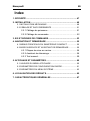
Index
1. SAFETY ......................................................................................2
2. INSTALLATION...........................................................................3
2.1 MECHANICAL INSTALLATION..................................................... 3
2.2 CABLING AND CONNECTIONS................................................... 5
2.2.1 Power cabling ..................................................................... 5
2.2.2 Control cabling .................................................................... 6
3. CONTROL I/O AND TERMINALS ..............................................7
4. NAVIGATION & STARTUP .........................................................9
4.1 THE MAIN MENUS OF SMARTDRIVE COMPACT ...................... 9
4.2 COMMISSIONING AND STARTUP WIZARD ............................... 10
4.2.1 Commissioning steps.......................................................... 10
4.2.2 Startup wizard ..................................................................... 10
4.2.3 Manual testing..................................................................... 12
5. MONITORING & PARAMETERS................................................13
5.1 MONITORING VALUES ................................................................ 13
5.2 QUICK SETUP PARAMETERS..................................................... 14
5.3 SYSTEM MENU PARAMETERS................................................... 16
6. FAULT TRACING........................................................................17
7. GENERAL DATA ........................................................................19

Honeywell Safety 2
1-EN
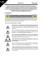
This quick guide includes the essential steps for easy
installation and setup of your SmartDrive Compact inverter.
Before commissioning your drive, read the complete
SmartDrive Compact User Manual available on the CD delivered with your
product or downloadable at:
http://ecc.emea.honeywell.com /inverter
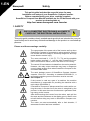
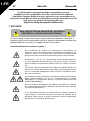
1. SAFETY
ONLY A COMPETENT ELECTRICIAN IS ALLOWED TO
CARRY OUT THE ELECTRICAL INSTALLATION
This quick guide contains clearly marked warnings which are intended for your per-
sonal safety and to avoid any unintentional damage to the product or connected ap-
pliances.
Please read these warnings carefully:
The components of the power unit of the inverter are live when
SmartDrive Compact is connected to mains potential. Coming
into contact with this voltage is extremely dangerous and may
cause death or severe injury.
The motor terminals U, V, W (T1, T2, T3) and the possible
brake resistor terminals -/+ are live when SmartDrive Com-
pact is connected to mains, even if the motor is not running.
The control I/O-terminals are isolated from the mains potential.
However, the relay output terminals may have a dangerous
control voltage present even when SmartDrive Compact is dis-
connected from mains.
The earth leakage current of SmartDrive Compact inverters
exceeds 3.5mA AC. According to standard EN61800-5-1, a
reinforced protective ground connection must be ensured.
See Chapter 7!
If the inverter is used as a part of a machine, the machine
manufacturer is responsible for providing the machine with a
main switch (EN 60204-1).
If SmartDrive Compact is disconnected from mains while run-
ning the motor, it remains live if the motor is energized by the
process. In this case the motor functions as a generator feed-
ing energy to the inverter.
After disconnecting the inverter from the mains, wait until the
fan stops and the indicators on the display go out. Wait 5 more
minutes before doing any work on SmartDrive Compact con-
nections.
The motor can start automatically after a fault situation, if
autorestart function has been activated.
!

3 Installation Honeywell
2-EN
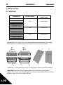
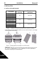
2. INSTALLATION
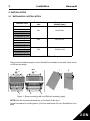
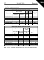
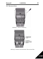
2.1 MECHANICAL INSTALLATION
There are two possible ways to mount SmartDrive Compact in the wall; either screw
or DIN-rail mounting.
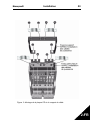
Figure 1: Screw mounting (left) and DIN-rail mounting (right)
NOTE! See the mounting dimensions on the back of the drive.
Leave free space for cooling above (100 mm) and below (50 mm) SmartDrive Com-
pact!
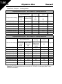
Product code
Mechanical
size
Dimensions
WxHxD [mm]
COMP230-P37-20
MI1 66x157x98
COMP230-P75-20
COMP400-P55-20
COMP400-P75-20
COMP400-1P1-20
MI2 90x195x102
COMP230-1P1-20
COMP230-1P5-20
COMP400-1P5-20
COMP400-2P2-20
COMP230-2P2-20
MI3 100x251x109
COMP400-3P0-20
COMP400-4P0-20
COMP400-5P5-20
Table 1: Mechanical size classes with SmartDrive Compact
12
MI2-3MI1
=M 4
=M 5

Honeywell Installation 4
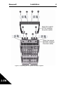
2-EN
Figure 2: Attaching the PE-plate and cable support

5 Installation Honeywell
2-EN
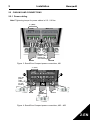
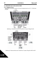
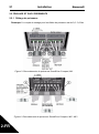
2.2 CABLING AND CONNECTIONS
2.2.1 Power cabling
Note! Tightening torque for power cables is 0.5 - 0.6 Nm
Figure 3: SmartDrive Compact power connections, MI1
Figure 4: SmartDrive Compact power connections, MI2 - MI3
1~ (230V)
3~ (400V)
Motor out
MAINS
MOTOR
Strip the
plastic cable
coating for
360° earthing
L1 L2/N L3 U/T1 V/T2 W/T3R+ R-
1~ (230V)
3~ (400V)
MAINS
MOTOR
BRAKE
RESISTOR
Str ip t he
plastic
cable
coating
for 360
°
earthing
External brake
re si s tor (4 00V)
Motor out

Honeywell Installation 6
2-EN
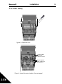
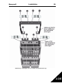
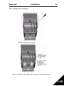
2.2.2 Control cabling
Figure 5: Open the cover
Figure 6: Install the control cables. See next page!
Strip the plastic
cable coating for
360
°
earthing
Control cable
tightening
torque: 0.4 Nm

7 Control I/O Honeywell
3-EN
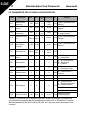
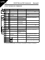
3. CONTROL I/O AND TERMINALS
Terminal Signal Factory preset Description
1 +10Vref Ref. voltage out Maximum load 10 mA
2 AI1 Analog signal in 1
Freq. reference
P)
0 - +10 V Ri = 200 k
(min)
3 GND I/O signal ground
6 24Vout 24V output for DI's ± 20 %, max. load 50 mA
7 GND I/O signal ground
8 DI1 Digital input 1
Start forward
P)
0 - +30 V Ri = 12 k min
9 DI2 Digital input 2
Start reverse
P)
10 DI3 Digital input 3
Preset speed B0
P)
A A RS485 signal A FB Communication Modbus
B B RS485 signal B FB Communication Modbus
4 AI2 Analog signal in 2
PI actual value
P)
0(4) - 20 mA, Ri = 200
5 GND I/O signal ground
13 GND I/O signal ground
14 DI4 Digital input 4
Preset speed B1
P)
0 - +30 V Ri = 12 k min
15 DI5 Digital input 5
Fault reset
P)
16 DI6 Digital input 6
Disable PI control
P)
18 AO Analog signal out
Output frequency
P)
0(4) - 20 mA, RL = 500
20 DO Digital signal out
Active = READY
P)
Open collector, max. load
48V/50mA
22 RO 11 Relay out 1
Active = RUN
P)
Max. switching load:
250Vac/2A or 250Vdc/
0,4A
23 RO 12
24 RO 21 Relay out 2
Active = FAULT
P)
Max. switching load:
250Vac/2A or 250Vdc/
0,4A
25 RO 22
26 RO 23
Table 1: Default I/O configuration and connections
P) = Programmable function, see User manual, Parameters
Ω
Ω
Ω
Ω
Ω
mA

Honeywell Control I/O 8
3-EN
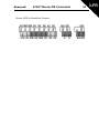
SmartDrive Compact I/O terminals:

9 Navigation & Startup Honeywell
4-EN
4. NAVIGATION & STARTUP
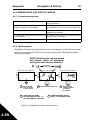
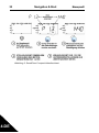
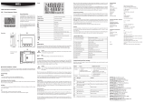
4.1 THE MAIN MENUS OF SMARTDRIVE COMPACT
Figure 1: The main menu of SmartDrive Compact
Hz
Hz
FWD REV I/O KEYPAD BUS
REF
MON
PA R
FLT
FAULTALARMSTOPREADY RUN
FWD REV I/O KEYPAD BUS
REF
PA R
FLT
FAULTALARMSTOPREADY RUN
MON
PUSH
FW D REV I/O KEYPAD BUS
REF
PAR
FLT
FAUL TALARMSTOPREADY RUN
MON
FWD REV I/O KEYPAD BUS
REF
PAR
FLT
FAULTALARMSTOPREADY RUN
MON
PUSH
FWD REV I/O KEYPAD BUS
REF
PAR
FLT
FAULTALARMSTOPREADY RUN
MON
FWD REV I/O KEYPAD BUS
REF
PAR
FLT
FAULTALARMSTOPREADY RUN
MON
PUSH
FWD REV I/O KEYPAD BUS
REF
PAR
FLT
FAU LTALARMSTOPREADY RUN
MON
ROTATE
ROTATE
ROTATE
REFERENCE
MENU
Displays the
keypad reference
value
regardless of
the selected
control place.
MONITORING
MENU
In this menu
you can
browse the
monitoring
values.
PARA MET ER
MENU
In this menu
you can
browse and
edit the
parameters.
FAULT MENU
Here you will
be able
to browse
through the
faults occurred.
PUSH
FWD REV I/O KEYPAD BUS
REF
MON
PA R
FLT
FAULTALARMSTOPREADY RUN

Honeywell Navigation & Startup 10
4-EN
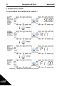
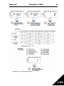
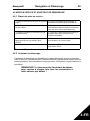
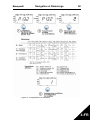
4.2 COMMISSIONING AND STARTUP WIZARD
4.2.1 Commissioning steps
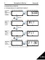
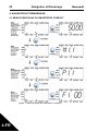
4.2.2 Startup wizard
SmartDrive Compact runs the startup wizard in first power-up. After that the wizard
can be run by pressing STOP for 5 seconds in main menu. The following figures
show the procedure.
NOTE! Running the startup wizard
will always return all parameter
settings to their factory defaults!
Figure 2: SmartDrive Compact startup wizard
1. Read safety instructions on page 1 6. Run the Startup wizard and set all neces-
sary parameters
2. Secure the grounding and check that
cables comply with requirements
7. Perform test run without motor, see the
User Manual: http://ecc.emea.honeywell.com
3. Check quality and quantity of cooling air 8. Run no-load tests without motor being con-
nected to the process
4. Check that all start/stop switches are in
STOP position
9. Connect the motor to the process and per-
form test run once again
5. Connect the drive to mains 10. SmartDrive Compact is now ready for use
Table 1: Commissioning steps
FAULTALARMSTOPREADY RUN
REF
MON
PAR
FLT
FAULTALARMSTO PREADY RUN
REF
MON
PAR
FLT
FAULTA LARMSTOPREADY RUN
REF
MON
PA R
FLT
rp m
Push to enter edit mode
Select motor
nominal speed
and push
to confirm.
Press STOP
for 5 seconds
in main menu
1
4
3
PERFORM THE SAME
PROCEDURE FOR PAR. 1.4,
MOTOR NOMINAL CURRENT
5
PERFORM DRIVE SETUP,
PAR. 13.2, SEE NEXT PAGE
2
Alternates
in the display

11 Navigation & Startup Honeywell
4-EN
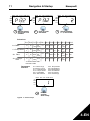
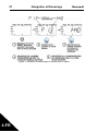
Figure 3: Drive setup
FAULTALARMSTOPREADY RUN
REF
MON
PAR
FLT
FAULTALARMSTO PREADY RUN
REF
MON
PAR
FLT
FAULTALARMSTOPREADY RUN
REF
MON
PA R
FLT
FAULTALARMSTOPREADY RUN
REF
MO N
PAR
FLT
0
Hz
50
Hz
3s 3s
1,1 *
I
400
V
*
50
Hz
0=
0=0=
0=
Ai1
0-10V
20
Hz
50
Hz
20 s
400 50
Hz
0=
0=
0= 0=
Ai1
0-10V
20
Hz
50
Hz
5s
400
50
Hz
0=
1=
0=
0=
Ai1
0-10V
0
Hz
50
Hz
1s
400
50
Hz
0=
0=1=
0=
Ai1
0-10V
NMOT
I/O
I/O
I/O
I/O
V
*
V
*
V
*
P3.2P3.1 P4 .2 P4.3
P1.7P1.1 P1.2
P2.2 P2.3P1.15 P3.3P2.1
1
2
3
4
1,1 *
I
NMOT
1,1 *
I
NMOT
1,5 *
I
NMOT
5s
20 s
1s
0
=Basic
*Indrivesof 208V...230V
thisvalue is 230V
1
=Pumpdrive
2
=
3
= Conveyor
drive
Push to enter
edit mode.
Select between
0 - 3, see below!
Selections:
Parameters
affected:
P3.2 Max freq uency
P3.1 Min frequency
P4.2 Acc. time (s)
P4.3 Dec time (s)
P1.7 Current limit (A)
P2.2 Start function
P2.3 Stop function
P1.15 Torque boost
P3.3 I/O reference
P2.1 Control place
Startup wizard
shows par 13.2
number.
Push to
confirm
drive setup
P1.1 Motor Un (V)
P1.2 Motor fn (Hz)
Ramp Coast.Not
used
Ramp
Coast .
Not
used
Ramp
Ramp
Not
used
Ramp
Coast.Used
Fans

Honeywell Navigation & Startup 12
4-EN
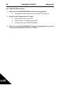
4.2.3 Manual testing
1. Hold NAVIGATION WHEEL down for 5 seconds
• Control Place automatically switches to manual control
2. Use the buttons for speed control
• START and STOP for control
• Move to reference menu REF
• NAVIGATION WHEEL for adjusting the speed
3. Hold NAVIGATION WHEEL down for 5 seconds to return to remote control
(I/O or fieldbus)

13 Monitoring & Parameters Honeywell
5-EN
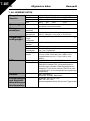
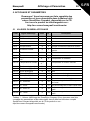
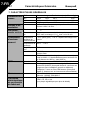
5. MONITORING & PARAMETERS
Note! Complete parameter listing and descriptions are
given in SmartDrive Compact User Manual, available on
the CD delivered with the product and downlodable at:
http://ecc.emea.honeywell.com/inverter
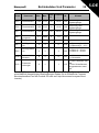
5.1 MONITORING VALUES
Code Monitoring signal Unit ID Description
M1.1 Output frequency Hz 1 Frequency to the motor
M1.2 Frequency reference Hz 25
M1.3 Motor shaft speed rpm 2 Calculated motor speed
M1.4 Motor current A 3 Measured motor current
M1.5 Motor torque % 4 Calculated actual/nominal torque of
the motor
M1.6 Motor power % 5 Calculated actual/nominal power of
the motor
M1.7 Motor voltage V 6 Motor voltage
M1.8 DC-link voltage V 7 Measured DC-link voltage
M1.9 Unit temperature
C
8 Heat sink temperature
M1.10 Motor temperature
C
Calculated motor temperature
M1.11 Analogue input 1 % 13 AI1 value
M1.12 Analogue input 2 % 14 AI2 value
M1.13 Analogue output % 26 AO1
M1.14 DI1, DI2, DI3 15 Digital input statuses
M1.15 DI4, DI5, DI6 16 Digital input statuses
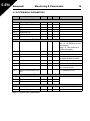
M1.16 RO1, RO2, DO 17 Relay/digital output statuses
M1.17 PI setpoint % 20 In percent of the maximum process
reference
M1.18 PI feedback % 21 In percent of the maximum actual
value
M1.19 PI error value % 22 In percent of the maximum error
value
M1.20 PI Output % 23 In percent of the maximum output
value
Table 1: SmartDrive Compact monitoring values (Complete parameter list and
parameter descriptions can be found from Complete SmartDrive Compact User
Manual available on product CD or at: http://ecc.emea.honeywell.com/inverter)
°
°

Honeywell Monitoring & Parameters 14
5-EN
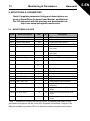
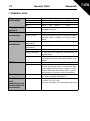
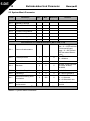
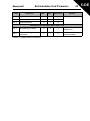
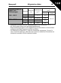
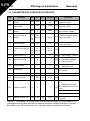
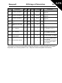
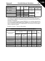
5.2 QUICK SETUP PARAMETERS
Code Parameter Min Max Unit Default ID Note
P1.1 Motor nominal
voltage
180 500 V 230
400
110 Check rating plate on the
motor
P1.2 Motor nom. fre-
quency
30 320 Hz 50,00 111 Check rating plate on the
motor
P1.3 Motor nominal
speed
300 2000
0
rpm 1440 112 Default applies for a
4-pole motor.
P1.4 Motor nominal
current
0,2 x
I
Nunit
1,5 x
I
Nunit
AI
Nunit
113 Check rating plate on the
motor
P1.5
Motor cos
0,30 1,00 0,85 120 Check rating plate on the
motor
P1.7 Current limit 0,2 x
I
Nunit
2 x
I
Nunit
A 1,5 x
I
Nunit
107
P1.15 Torque boost 0 1 0 109 0 = Not used 1 = Used
P2.1 Control place 1 3 1 125 1 = I/O termina
2 = Keypad
3 = Fieldbus
P2.2 Start function 0 1 0 505 0 = Ramp 1 = Flying start
P2.3 Stop function 0 1 0 506 0 = Coasting 1 = Ramp
P3.1 Min frequency 0,00 P3.2 Hz 0,00 101
P3.2 Max frequency P3.1 320 Hz 50,00 102
P3.3 I/O reference 0 4 3 117 0 = Preset Speeds (0-7)
1 = Keypad Reference
2 = Fieldbus Reference
3 = AI1
4 = AI2
P3.4 Preset speed 0 0,00 P3.2 Hz 5,00 124 Activated by digital inputs
P3.5 Preset speed 1 0,00 P3.2 Hz 10,00 105 Activated by digital inputs
P3.6 Preset speed 2 0,00 P3.2 Hz 15,00 106 Activated by digital inputs
P3.7 Preset speed 3 0,00 P3.2 Hz 20,00 126 Activated by digital inputs
Table 2: Quick setup parameters (Complete parameter list and parameter descriptions
can be found from Complete SmartDrive Compact User Manual available on product
CD or at: http://ecc.emea.honeywell.com/inverter)
ϕ

15 Monitoring & Parameters Honeywell
5-EN
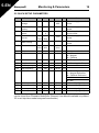
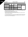
P4.2 Acceleration time 0,1 3000 s 1,0 103
P4.3 Deceleration time 0,1 3000 s 1,0 104
P6.1 AI1 Signal range 0 3 0 379 0 = Voltage 0…10 V
1 = Voltage 2…10 V
P6.5 AI2 Signal range 2 3 3 390 2 = Current 0…20 mA
3 = Current 4…20 mA
P10.4 Automatic restart 0 1 0 731 0 = Not used 1 = Used
P13.1 Parameter
conceal
01 11150 = All parameters visible
1 = Only quick setup
parameters visible
Code Parameter Min Max Unit Default ID Note
Table 2: Quick setup parameters (Complete parameter list and parameter descriptions
can be found from Complete SmartDrive Compact User Manual available on product
CD or at: http://ecc.emea.honeywell.com/inverter)

Honeywell Monitoring & Parameters 16
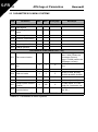
5-EN
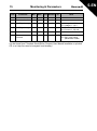
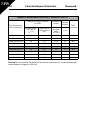
5.3 SYSTEM MENU PARAMETERS
Code Parameter Min Max Default Note
Software information (MENU PAR -> S1)
S1.1 Software package
S1.2 Power SW version
S1.3 SW version
S1.4 Firmware interface
S1.5 Application ID
S1.6 Application revision
S1.7 System load
RS485 information (MENU PAR -> S2)
S2.1 Communication status Format: xx.yyy
xx = 0 - 64 (Number of error
messages)
yyy = 0 - 999 (Number of
good messages)
S2.2 Fieldbus protocol 0 1 0 0 = FB disabled 1= Modbus
S2.3 Slave address 1 255
S2.4 Baud rate 0 5 5 0=300, 1=600, 2=1200,
3=2400, 4=4800, 5=9600,
S2.5 Number of stop bits 0 1 1 0=1, 1=2
S2.6 Parity type 0 0 0 0= None (locked)
S2.7 Communication time-out 0 255 0 0= Not used, 1= 1 second,
2= 2 seconds, etc.
S2.8 Reset communication sta-
tus
1= Resets par. S2.1
Total counters (MENU PAR -> S3)
S3.1 MWh counter 0 1 0
S3.2 Power on days 0 1 0
S3.3 Power on hours 0 1 0
User settings (MENU PAR -> S4)
S4.1 Display contrast 0 15 7 Adjusts the display contrast
S4.2 Restore factory defaults 0 1 0 1= Restores factory defaults
Table 3: System menu parameters

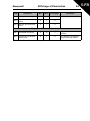
17 Fault Tracing Honeywell
6-EN
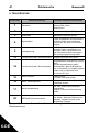
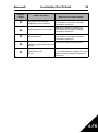
6. FAULT TRACING
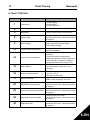
Fault code Fault name Quick corrective actions
1
Overcurrent
- Check loading.
- Check cables.
- Check motor size.
2
Overvoltage Increase deceleration time (P4.3).
3
Earth fault - Check motor Cables- Check motor.
8
System fault
Reset the fault and restart.
Should the fault recur, contact the techni-
cal support.
9
Undervoltage
In case of temporary supply voltage
break, reset the fault and restart.
Check supply voltage.
13
Inverter under temperature
Check that the product is operated in
specified conditions.
14
Inverter over temperature
- Check that the cooling air is not
blocked.
- Check the ambient temperature.
- Make sure that the switching frequency
is not too high in relation to ambient
temperature and motor load (P1.16).
15
Motor stalled
- Check motor
- Check that the pump or fan is not
blocked.
16
Motor overtemperature
- Check that motor parameters are cor
rect (P1.1-P1.5).
- Decrease motor load.
17
Motor Underload
FAN: check that belt is not broken.
PUMP: check that pump is not dry.
22
EEPROM checksum fault
Reset the fault and restart.
Should the fault recur, contact the techni-
cal support.
25
Microcontroller watchdog fault
Reset the fault and restart.
Should the fault recur, contact the techni-
cal support.
34
Internal bus communication
Reset the fault and restart.
Should the fault recur, contact the techni-
cal support.
35
Application fault
Reset the fault and restart.
Should the fault recur, contact the techni-
cal support.

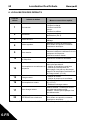
Honeywell Fault Tracing 18
6-EN
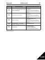
Table 1: Fault codes. See User Manual for detailed fault descriptions
50
Analogue input Iin < 4mA
(selected signal range 4 to 20
mA)
Check the control cabling
53
Fieldbus fault
- Check installation.
- If installation is correct contact technical
support
Fault code Fault name Quick corrective actions
La page est en cours de chargement...
La page est en cours de chargement...
La page est en cours de chargement...
La page est en cours de chargement...
La page est en cours de chargement...
La page est en cours de chargement...
La page est en cours de chargement...
La page est en cours de chargement...
La page est en cours de chargement...
La page est en cours de chargement...
La page est en cours de chargement...
La page est en cours de chargement...
La page est en cours de chargement...
La page est en cours de chargement...
La page est en cours de chargement...
La page est en cours de chargement...
La page est en cours de chargement...
La page est en cours de chargement...
La page est en cours de chargement...
La page est en cours de chargement...
La page est en cours de chargement...
La page est en cours de chargement...
La page est en cours de chargement...
La page est en cours de chargement...
La page est en cours de chargement...
La page est en cours de chargement...
La page est en cours de chargement...
La page est en cours de chargement...
La page est en cours de chargement...
La page est en cours de chargement...
La page est en cours de chargement...
La page est en cours de chargement...
La page est en cours de chargement...
La page est en cours de chargement...
La page est en cours de chargement...
La page est en cours de chargement...
La page est en cours de chargement...
La page est en cours de chargement...
La page est en cours de chargement...
La page est en cours de chargement...
La page est en cours de chargement...
La page est en cours de chargement...
La page est en cours de chargement...
La page est en cours de chargement...
La page est en cours de chargement...
La page est en cours de chargement...
La page est en cours de chargement...
La page est en cours de chargement...
La page est en cours de chargement...
La page est en cours de chargement...
La page est en cours de chargement...
La page est en cours de chargement...
La page est en cours de chargement...
La page est en cours de chargement...
-
 1
1
-
 2
2
-
 3
3
-
 4
4
-
 5
5
-
 6
6
-
 7
7
-
 8
8
-
 9
9
-
 10
10
-
 11
11
-
 12
12
-
 13
13
-
 14
14
-
 15
15
-
 16
16
-
 17
17
-
 18
18
-
 19
19
-
 20
20
-
 21
21
-
 22
22
-
 23
23
-
 24
24
-
 25
25
-
 26
26
-
 27
27
-
 28
28
-
 29
29
-
 30
30
-
 31
31
-
 32
32
-
 33
33
-
 34
34
-
 35
35
-
 36
36
-
 37
37
-
 38
38
-
 39
39
-
 40
40
-
 41
41
-
 42
42
-
 43
43
-
 44
44
-
 45
45
-
 46
46
-
 47
47
-
 48
48
-
 49
49
-
 50
50
-
 51
51
-
 52
52
-
 53
53
-
 54
54
-
 55
55
-
 56
56
-
 57
57
-
 58
58
-
 59
59
-
 60
60
-
 61
61
-
 62
62
-
 63
63
-
 64
64
-
 65
65
-
 66
66
-
 67
67
-
 68
68
-
 69
69
-
 70
70
-
 71
71
-
 72
72
-
 73
73
-
 74
74


Honeywell SMARTDRIVE COMPACT Le manuel du propriétaire
- Taper
- Le manuel du propriétaire
dans d''autres langues
Documents connexes
Autres documents
-
Emotron DSV15-35 Mounting Instruction
-
Vacon nxs Guide d'installation
-
Sentiotec SwitchBox Manuel utilisateur
-
Permobil SM-MX2-168 Manuel utilisateur
-
SBC Application Le manuel du propriétaire
-
Husqvarna PG 530 Le manuel du propriétaire
-
Omron VARISPEED V7 IP65 CIMR-V7TZ*-05 Guide de démarrage rapide
-
 Allen-Bradley 931S-F1C2D-DC Installation Instructions Manual
-
D+H GE 650-Set Mode d'emploi
-
 Rotronic HD1 Short Instruction Manual

