Maytag MBF1956HE Mode d'emploi
- Catégorie
- Congélateurs
- Taper
- Mode d'emploi
Ce manuel convient également à

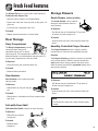
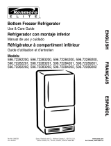
Bottom Freezer
Use & Care Guide
R
Form No. B/12/04 Part No. 12828120 www.maytag.com ©2004 Maytag Appliances Sales Co. Litho U.S.A.
Table of Contents
Important Safety
Instructions.................................... 1-2
Installation................................... 3-10
Temperature Controls.............. 11-14
Fresh Food Features .................15-17
Freezer Features....................... 18-19
Food Storage Tips.................... 20-22
Care and Cleaning................... 23-26
Operating Sounds .......................... 27
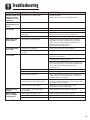
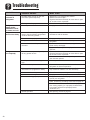
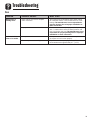
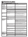
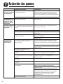
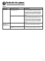
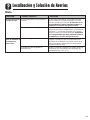
Troubleshooting........................ 28-30
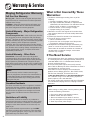
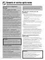
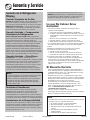
Warranty & Service ........................ 31
Guide d’utilisation et
d’entretien........................................ 32
Guía de Uso y Cuidado ................. 68

1
Important Safety Instructions
WARNING – Hazards or unsafe practices which
COULD result in severe personal injury or death.
WARNING
DANGER – Immediate hazards which WILL result
in severe personal injury or death.
DANGER
CAUTION – Hazards or unsafe practices which COULD
result in minor personal injury or property damage.
CAUTION
What You Need to Know About
Safety Instructions
Warning and Important Safety Instructions appearing in
this guide are not meant to cover all possible
conditions and situations that may occur. Common
sense, caution and care must be exercised when
installing, maintaining or operating appliance.
Always contact the manufacturer about problems or
conditions you do not understand.
Recognize Safety Symbols, Words,
Labels
Installer: Please leave this guide with this appliance.
Consumer: Please read and keep this Use & Care
Guide for future reference. This guide provides
proper use and maintenance information.
Keep sales receipt and/or cancelled check as proof
of purchase.
Call: 1-800-688-9900 U.S.A.
1-800-688-2002 Canada
Have complete model and serial number
identification of your refrigerator. This is located on a
data plate inside the refrigerator compartment, on
the upper left side. Record these numbers below for
easy access.
Model Number _______________________________
Revision Number ______________________________
Serial Number ________________________________
Date of Purchase______________________________
In our continuing effort to improve the quality and
performance of our appliances, it may be necessary
to make changes to the appliance without revising
this guide.
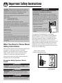
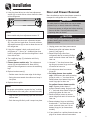
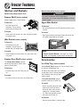
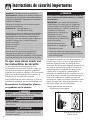
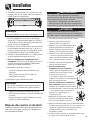
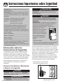
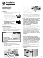
This appliance is equipped with a three-prong
grounding plug for your protection against possible
electrical shock hazards. It must be plugged into a
grounding receptacle. Where a standard two-prong
wall receptacle is encountered, it is the personal
responsibility and obligation of the customer to have it
replaced with a properly grounded three-prong wall
receptacle. Do not under any circumstances, cut or
remove the third (ground) prong from the power cord.
Do not use an adapter plug.
Power supply cord with
three-prong grounding plug
Grounding type
wall receptacle
To reduce risk of injury or death, follow basic
precautions, including the following:
IMPORTANT: Child entrapment and suffocation
are not problems of the past. Junked or abandoned
refrigerators are still dangerous – even if they sit out
for “just a few days.” If you are getting rid of your old
refrigerator, please follow the instructions below to
help prevent accidents.
Before you throw away your old
refrigerator or freezer:
•Take off the doors.
•Leave the shelves in place so
children may not easily climb
inside.
DANGER

2
Important Safety Instructions
SAVE THESE INSTRUCTIONS
To reduce risk of fire, electric shock, serious injury or
death when using your refrigerator, follow these basic
precautions, including the following:
1. Read all instructions before using the refrigerator.
2. Observe all local codes and ordinances.
3. Be sure to follow grounding instructions.
4. Check with a qualified electrician if you are not
sure this appliance is properly grounded.
5. Do not ground to a gas line.
6. Do not ground to a cold-water pipe.
7. Refrigerator is designed to operate on a separate
115 volt, 15 amp., 60 cycle line.
8. Do not modify plug on power cord. If plug does
not fit electrical outlet, have proper outlet installed
by a qualified electrician.
9. Do not use a two-prong adapter, extension cord
or power strip.
10. Do not remove warning tag from power cord.
11. Do not tamper with refrigerator controls.
12. Do not service or replace any part of refrigerator
unless specifically recommended in Use & Care
Guide or published user-repair instructions. Do
not attempt service if instructions are not under-
stood or if they are beyond personal skill level.
13. Always disconnect refrigerator from electrical
supply before attempting any service. Disconnect
power cord by grasping the plug, not the cord.
14. Install refrigerator according to Installation
Instructions. All connections for water, electrical
power and grounding must comply with local
codes and be made by licensed personnel when
required.
15. Keep your refrigerator in good condition. Bumping
or dropping refrigerator can damage refrigerator
or cause refrigerator to malfunction or leak. If
damage occurs, have refrigerator checked by
qualified service technician.
16. Replace worn power cords and/or loose plugs.
17. Always read and follow manufacturer’s storage
and ideal environment instructions for items being
stored in refrigerator.
18. Your refrigerator should not be operated in the
presence of explosive fumes.
19. Children should not climb, hang or stand on any
part of the refrigerator.
20. Clean up spills or water leakage associated with
water installation.
WARNING

3
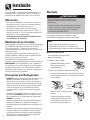
Installation
Your refrigerator was packed carefully for shipment.
Remove and discard shelf packaging and tape. Do not
remove the serial plate.
Location
• Do not install refrigerator near oven, radiator or other
heat source. If not possible, shield refrigerator with
cabinet material.
• Do not install where temperature falls below 55° F
(13° C) or rises above 110° F (43° C). Malfunction
may occur at this temperature.
• Refrigerator is designed for indoor household
application only.
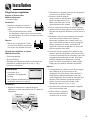
Measuring the Opening
When installing your refrigerator, measure carefully.
Allow
1
⁄2” space at top and
1
⁄2” space behind the
machine compartment cover (located in the rear) for
proper air circulation.
Subflooring or floor coverings (i.e. carpet, tile, wood
floors, rugs) may make your opening smaller than
anticipated.
Some clearance may be gained by using the leveling
procedure under Leveling.
IMPORTANT: If refrigerator is to be installed into a
recess where the top of the refrigerator is completely
covered, use dimensions from floor to top of hinge cap
to verify proper clearance.
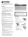
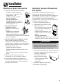
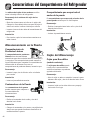
Transporting Your Refrigerator
• NEVER transport refrigerator on its side. If an
upright position is not possible, lay refrigerator on its
back. Allow refrigerator to sit upright for
approximately 30 minutes before plugging it in to
assure oil returns to the compressor. Plugging the
refrigerator in immediately may cause damage to
internal parts.
• Use an appliance dolly when moving refrigerator.
ALWAYS truck refrigerator from its side or
back–NEVER from its front.
•Protect outside finish of refrigerator during transport
by wrapping cabinet in blankets or inserting padding
between the refrigerator and dolly.
• Secure refrigerator to dolly firmly with straps or
bungee cords. Thread straps through handles when
possible. Do not overtighten. Overtightening
restraints may dent or damage outside finish.
Leveling
To protect property and refrigerator from damage,
observe the following:
•Protect vinyl or other flooring with cardboard, rugs,
or other protective material.
• Do not use power tools when performing leveling
procedure.
CAUTION
To enhance the appearance and maintain performance,
the refrigerator should be level.
Note
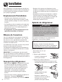
• Complete any required door reversal, panel
installation and/or a water supply connection,
before leveling.
Materials Needed:
•
3
⁄8” hex head driver
• Carpenter’s level
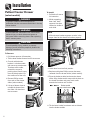
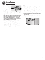
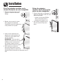
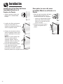
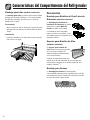
1. Remove toe grille.
• Grasp firmly and pull outward
to unclip.
2. Remove bottom bracket cover(s).
• Place the eraser end of a pencil or similar blunt
tool in the cover notch.
Notch
Location
• Use slight pressure to pry the
cover loose.
• Continue to maintain
downward pressure to the
notched side of the cover while
swinging it off.

4
Installation
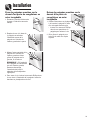
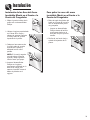
CC
A
B
A
B
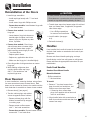
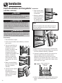
4. Select models also have rear adjustment screws
(B). Using the hex head driver, turn each of these
adjustment screws (B) to raise or lower the rear of
the refrigerator.
5. Using the carpenter’s level, make sure front of
refrigerator is
1
⁄4” (6 mm) or
1
⁄2 bubble higher than
back of refrigerator and that the refrigerator is level
from side to side.
6. Turn stabilizing legs (C) clockwise until firmly
against floor.
7. Freezer drawer models only: Turn adjustment
screws (A) counterclockwise to allow the full
weight of the refrigerator to rest on the stabilizing
legs.
8. Replace bracket cover(s).
•Position cover into the outer edge of the hinge.
•Swing the cover toward the cabinet and snap it
into place.
9. Replace the toe grille.
To avoid electrical shock which can cause severe
personal injury or death, observe the following:
• Disconnect power to refrigerator before removing
doors or drawer. Connect power only after
replacing doors or drawer.
WARNING
To avoid damage to walls and flooring, protect vinyl
or other flooring with cardboard, rugs or other
protective material.
CAUTION
1. Unplug power cord from power source.
2. Remove toe grille and bottom bracket
cover(s) (see page 3).
3. Remove top hinge cover from
refrigerator door by removing Phillips
screw and retain screw and cover for
later use.
4. Unscrew
5
⁄16” hex head screws from
top hinge to remove hinge and retain
all screws for later use.
5. Lift refrigerator door from center
hinge pin.
6. For swing freezer door models
only: Hold freezer door while removing
hinge pin with a
5
⁄16” hex head driver.
Remove door from bottom hinge and
retain hinge pin for later use.
For pullout freezer drawer models
only: Remove plastic sleeve, if
present. Remove center hinge pin with
a
5
⁄16” hex head driver. Retain hinge pin
and plastic sleeve for later use.
7. Remove Phillips screws to remove
center hinge and retain all screws for
later use.
8. Remove bottom hinge or stabilizing
bracket with
3
⁄8” hex head driver and
retain screws for later use. Lift out
bottom hinge pin (on freezer door
models).
9. If your model has a pullout freezer drawer, see
page 5 for drawer removal instructions.
Note
•For proper reinstallation, ensure the “top” marking
on the interior of the toe grille is oriented correctly.
• Align the toe grille mounting clips with the lower
cabinet slots.
•Push the toe grille firmly until it snaps into place.
Note
• Some models only have adjustment screws “A.”
Door and Drawer Removal
Some installations require door/drawer removal to
transport the refrigerator to its final location.
3. Using hex head driver, turn the front adjustment
screws (A) on each side to raise or lower the front
of the refrigerator.

5
Installation
Pullout Freezer Drawer
(select models)
To avoid electrical shock which can cause severe
personal injury or death, disconnect power to
refrigerator before removing doors. After replacing
doors, connect power.
WARNING
To prevent accidental child entrapment or
suffocation risk, do not remove the divider in the top
freezer basket.
DANGER
To avoid possible injury, product, or property
damage, you will need two people to perform the
following instructions.
CAUTION
To Remove:
1. Pull drawer open to full extension.
2. Tilt the lower basket forward and lift to remove.
3. On each white drawer
bracket is a basket cradle
with two snap attachments.
To release each cradle,
unlatch the snaps by
pushing them inward, away
from the side bracket. Lift
the cradles off of the rails.
4. Remove Phillips screw
from each of the drawer
slides (select models).
5. Lift top of drawer front to
unhook the drawer from
the slides. Lift door front
out to remove.
To Install:
1. Pull both rails out to
full extension.
2. While supporting
door front, hook
supports into slots
located on inside of
each slide.
Note
• All four drawer bracket supports must be in the
proper slots for the drawer to function properly.
6. Tilt the lower basket front down and set it down
into the basket cradles.
Basket cradle
snap attachments
3. Lower door front into final position.
4. Replace and tighten Phillips screws that were
removed from the drawer slides (select models).
5. Place the basket cradles back onto the drawer
slides. Align basket cradle snaps with the slots on
the drawer brackets and press each cradle
towards the bracket until it clicks.

6
Installation
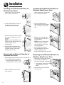
Reinstallation of the Doors
1. Install hinge assemblies:
• Install top hinge loosely with
5
⁄16” hex head
screws.
• Install center hinge with Phillips screws.
• Freezer door models: Install bottom hinge with
3
⁄8” hex head screws.
2. Freezer door models: Insert bottom
hinge pin.
•Locate bottom hinge hole closest to
outside edge of cabinet, and insert
bottom hinge pin. Replace any door
shims, if present.
3. Freezer door models: Place hinge
side of freezer door on bottom hinge
pin and hold freezer door upright
while installing center hinge pin with
5
⁄16” hex head driver.
• Replace plastic sleeve.
• Replace any applicable door shims.
• Make sure the hinge pin is installed tightly.
4. Place hinge side of refrigerator door on center
hinge pin.
5. While holding refrigerator door
upright, tighten down top hinge
with
5
⁄16” hex head driver and
replace hinge cover.
Door Reversal
In some installations, reversing the door swing allows
for more convenient access to stored items. Both
doors can be reversed on freezer door models and the
fresh food door is reversible on freezer drawer models.
1. Remove door(s) (see page 4).
2. Transfer cabinet plugs and cabinet
screws to opposite side of cabinet.
• Remove cabinet plugs with flat
blade of screwdriver tip wrapped
in masking tape.
• Remove center mullion screws
with
5
⁄16” hex head screwdriver.
• Freezer door models: Remove bottom mullion
screws with
3
⁄8” hex head driver.
3. Transfer door stops from bottom edge of fresh food
door and freezer door, if applicable, to opposite
side of door edge.
•Use a Phillips screwdriver
for removal and installation.
4. Install handles (see pages
6-9).
5. Reinstall the door(s).
Handles
If not installed, the handle is located in the interior of
the fresh food section or attached to the back of your
refrigerator.
Remove and discard handle packaging and tape.
Handle design varies from refrigerator to refrigerator.
Please reference the appropriate instructions for your
model below.
Fresh Food Handles
Standard Front Mount Handle
Materials Needed:
• Phillips screwdriver
•
5
⁄16” hex head driver
To Install:
1. Remove
1
⁄4” hex head screws from
door face with hex head driver, and
Phillips screw from top of door.
• If reversing door, remove door
plugs from opposite side of door and
insert in screw holes.
2. Align handle holes with screw holes on
door face and secure with two door face
screws from step 1.
To avoid possible injury and damage to property:
• Place doors on a nonabrasive surface protected by
towels or rugs while working directly on doors.
CAUTION

3. Locate handle trim in literature pack and
install over top and bottom of handle, as
illustrated.
• Secure top handle trim with remaining
screw removed in step 1.
•Snap bottom trim over bottom portion
of handle.
To Remove:
1. Remove top handle trim by removing top
handle screw.
• Retain trim and screw for later
replacement.
2. Pry bottom handle trim from handle with
screwdriver flat blade wrapped in
masking tape.
• Retain trim for later replacement.
3. Remove two hex head screws.
• Retain screws for later replacement.
Side Mount Handle
Materials Needed:
• Phillips screwdriver
To Install:
1. Remove screws from the side of the
door.
2. Align the side mount handle with the
predrilled holes in the door panel.
3. Insert the screws in the sequence as
shown.
7
Installation
4. Ensure the door handle is snug to the
door panel.
To Remove:
Reverse installation procedure.
Upper
Handle
Lower
Handle
1
3
2
4
Notes
•There is a slight curve to
this style of freezer
handle.
•For proper installation, be
sure handle is oriented as shown.
To Install:
1. Align door handle clips slightly to the left of the
tabs attached to the freezer door.
2. Rotate the handle so the left base is flat against
the door.
Freezer Handles
Partial-Width Handle
Materials Needed:
• Phillips screwdriver
To Install:
1. Install handle by fastening with
screws removed from edge of door.
• If reversing freezer door, remove
door plugs from top edge of door
and insert into screw holes.
To Remove:
1. Remove handle screws with Phillips
screwdriver and retain screws for
later use.
Front Mount Freezer Handle
Materials Needed:
• Gloves to protect hands.
• Phillips screwdriver.
• Plastic handle removal card (or
1
⁄32” thick plastic
card). Retain the card.
Handle
Clip
Handle
Base
Door
Tab

Installation
8
3. Push the left handle
base against the left
door tab and slightly
to the right, just
enough to allow it to
hang unsupported.
4. While firmly supporting the left handle base against
the door, align the right base of the handle with the
right tabs that are attached to the door.
5. Now, while firmly holding the handle at the left and
right bases, gently slide the handle towards the
right until the right base settles in. The handle
should now be flat against the face of the freezer
door at both the left and right bases.
6. With hands still firmly keeping the handle flat
against the freezer door, you may have to reverse
directions momentarily to assure clip/tab
engagement. Then firmly slide the handle to the
right until it clicks. The audible “click” indicates
that the fastening clips are securely interlocked.
To Remove:
1. At the right end, flex the handle base away from
the surface of the freezer drawer. Simultaneously
slide the door handle removal card that came with
your refrigerator under the right side base of the
handle. Slide the card to the line indication or until
it stops, which will be approximately 1
1
⁄2”.
2. With both hands, firmly grasp the handle towards
the right base.
3. Slide towards the left, lift and remove from the
surface.

9
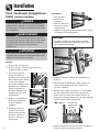
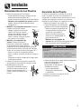
Installing Front-Mounted Handles for
Stainless Steel Door
1. Loosen lower door clip on door
with a phillips screwdriver.
2. Locate predrilled hole at base of
handle, and fit hollow end of
handle over lower door clip.
3. Fit other end of handle over upper
door clip and slide up as far as
possible.
NOTE: If top of handle does not
fit over top clip, loosen lower clip
further until fit can be
accomplished.
4. Insert phillips screwdriver into
predrilled hole at base of handle
to tighten screw. Insert plastic
button plug into hole.
Removing Front-Mounted Handles for
Stainless Steel Door
1. Remove plastic button plug at base of handle with a
very small flat-blade screwdriver.
• Insert phillips screwdriver into
predrilled hole to remove screw.
2. Slide handle down and remove
from door clip.
Installation
Installing Front-Mounted Handles for
Stainless Steel Freezer Door
1. Loosen lower door clip on door
with a phillips screwdriver.
2. Locate predrilled hole at
base of handle, and fit hollow
end of handle over left door
clip.
3. Fit other end of handle over
left door clip and slide left as
far as possible.
NOTE: If end of handle does
not fit over left clip, loosen
right clip further until fit can
be accomplished.
4. Insert phillips screwdriver
into predrilled hole at end of
handle to tighten screw.
Insert plastic button plug into hole.
Removing Front-Mounted Handles for
Stainless Steel Freezer Door
1. Remove right side plastic button
plug at end of handle with a
very small flat-blade screwdriver.
• Insert phillips screwdriver into
predrilled hole to remove
screw.
2. Slide handle right and remove
from door clip.

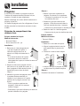
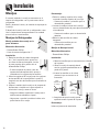
Connecting the Water Supply
(select models)
To reduce the risk of injury or death, follow
basic precautions, including the following:
• Read all instructions before installing ice maker.
•Do not attempt installation if instructions are not
understood or if they are beyond personal skill
level.
• Observe all local codes and ordinances.
• Do not service ice maker unless specifically
recommended in Use & Care Guide or published
user-repair instructions.
• Disconnect power to refrigerator before installing
ice maker.
•Water damage due to an improper water
connection may cause mold/mildew growth.
Clean up spills or leakage immediately.
WARNING
To avoid property damage or possible injury,
follow basic precautions, including the
following:
• Consult a plumber to connect
1
⁄4” O.D. copper
tubing to household plumbing to assure
compliance with local codes and ordinances.
• Confirm water pressure to water valve is between
35 and 100 pounds per square inch. 20 pounds
per square inch if there is not a water filter.
• Do not use a self-piercing, or
3
⁄16” saddle valve.
Both reduce water flow and can become clogged
over time, and may cause leaks if repair is
attempted.
•Tighten nuts by hand to prevent cross threading.
Finish tightening nuts with pliers and wrenches.
Do not overtighten.
•Wait 2-3 hours before placing refrigerator into final
position to check and correct any water leaks.
Recheck for leaks after 24 hours.
•Verify the copper tubing under the sleeve is
smooth and free from defects. Do not reuse an old
sleeve.
CAUTION
Materials Needed:
•
1
⁄4” outer diameter flexible copper tubing
• Shut-off valve (requires a
1
⁄4” hole to be drilled into
water supply line before valve attachment)
• Adjustable wrench
•
1
⁄4” hex nut driver
IMPORTANT: Do not overtighten. Cross
threading may occur.
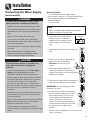
6. Pull on tubing to confirm connection is
secure. Connect tubing to frame with
water tubing clamp (C) and turn on
water supply. Check for leaks and
correct if necessary. Continue to
observe the water supply connection
for two to three hours prior to moving
the refrigerator to its permanent
location.
7. Monitor water connection for 24 hours. Correct
leaks, if necessary.
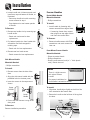
Note
•Add 8’ to tubing length needed to reach water
supply for creation of service loop.
1. Create service loop with copper
tubing (minimum 2’ diameter).
Avoid kinks in the copper tubing
when bending it into a service
loop.
2. Remove plastic cap from water valve inlet
port.
3. Place brass nut (A) and sleeve (B) on
copper tube end as illustrated.
Reminder: Do not use an old
sleeve.
4. Place end of copper tubing into
water valve inlet port. Shape tubing
slightly. Do not kink – so that tubing feeds
straight into inlet port.
5. Slide brass nut over sleeve and screw nut
into inlet port. Tighten nut with wrench.
Installation
C
A
B
2’ diameter
minimum
10

11
Temperature Controls
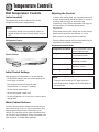
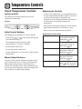
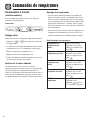
Dial Temperature Controls
(select models)
The controls are located at the top front of the
refrigerator and freezer compartments.
Note
•The freezer control turns the cooling system on.
Neither section will cool if freezer control is set to
OFF.
Refrigerator Control
Freezer Control
Initial Control Settings
After plugging the refrigerator in, set the controls.
•To adjust the controls, turn the control knob to the
left or right as desired.
•The temperature control range for both
compartments is 1 through 7 (coldest).
• Set the freezer control on 4.
• Set the refrigerator control on 4.
•Let the refrigerator run at least 8 to 12 hours before
adding food.
Warm Cabinet Surfaces
At times, the front of the refrigerator cabinet may be
warm to the touch. This is a normal occurrence that
helps prevent moisture from condensing on the
cabinet. This condition will be more noticeable when
you first start the refrigerator, during hot weather and
after excessive or lengthy door openings.
Adjusting the Controls
• 24 hours after adding food, you may decide that one
or both compartments should be colder or warmer. If
so, adjust the control(s) as indicated in the
Temperature Control Guide table below. See page 20
for instructions on checking compartment
temperature.
• Except when starting the refrigerator, do not change
either control more than one number at a time.
• Allow 24 hours for temperatures to stabilize.
• Changing either control will have some effect on the
temperature of the other compartment.
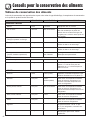
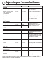
Temperature Control Guide
Refrigerator too warm
Refrigerator too cold
Freezer too warm
Freezer too cold
Turn refrigerator OFF
Turn the refrigerator control
to next higher number.
Turn the refrigerator control
to next lower number.
Turn the freezer control to
next higher number.
Turn the freezer control to
next lower number.
Turn the freezer control to
OFF.
Note
•Turning freezer control to OFF stops cooling in
both compartments. It does not shut off power to
the refrigerator.

12
Temperature Controls
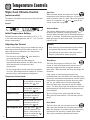
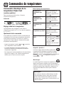
Touch Temperature Controls
(select models)
The controls are located at the top front of the
refrigerator compartment.
Control
Initial Control Settings
After plugging the refrigerator in, set the controls.
•Pressing the or pads adjusts the controls
to the desired setting.
•The temperature control range for both
compartments is 1 through 7 (coldest).
• Set the freezer control on 4.
• Set the refrigerator control on 4.
•Let the refrigerator run at least 8 to 12 hours before
adding food.
Warm Cabinet Surfaces
At times, the front of the refrigerator cabinet may be
warm to the touch. This is a normal occurrence that
helps prevent moisture from condensing on the
cabinet. This condition will be more noticeable when
you first start the refrigerator, during hot weather and
after excessive or lengthy door openings.
Adjusting the Controls
• 24 hours after adding food, you may decide that one
or both compartments should be colder or warmer. If
so, adjust the control(s) as indicated in the
Temperature Control Guide table below. See page 20
for instructions on checking compartment
temperature.
• Except when starting the refrigerator, do not change
either control more than one number at a time.
• Allow 24 hours for temperatures to stabilize.
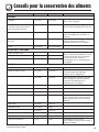
Temperature Control Guide
Refrigerator too warm
Refrigerator too cold
Freezer too warm
Freezer too cold
Turn refrigerator OFF
Set the refrigerator control
to next higher number by
pressing the pad.
Set the refrigerator control
to next lower number by
pressing the pad.
Set the freezer control to
next higher number by
pressing the pad.
Set the freezer control to
next lower number by
pressing the pad.
Press the refrigerator or
freezer pad until a dash
(—) appears in the display.

13
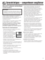
Temperature Controls
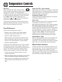
Triple Cool Climate Control
(select models)
The control is located at the top front of the fresh food
compartment.
Control
Initial Temperature Setting
Temperatures are preset at the factory at 38° F (3° C)
in the fresh food compartment and 0° F (-18° C) in the
freezer compartment.
Adjusting the Control
24 hours after adding food, you may decide that one or
both compartments should be colder or warmer. If so,
adjust the control as indicated in the Temperature
Control Guide below.
•The first touch of the or pads shows the
current temperature setting.
•The display will show the new setting for
approximately three seconds, and then return to the
actual temperature currently within that
compartment.
• Do not change either control more than one degree
at a time. Allow temperature to stabilize for 24 hours
before making a new temperature adjustment.
Temperature Control Guide
Refrigerator too cold
Refrigerator too warm
Freezer too cold
Freezer too warm
Turn refrigerator OFF
Set the refrigerator control
to next higher number by
pressing the pad.
Set the refrigerator control
to next lower number by
pressing the pad.
Set the freezer control to
next higher number by
pressing the pad.
Set the freezer control to
next lower number by
pressing the pad.
Press the freezer pad
until OFF appears in the
display. Press either the
freezer or refrigerator
pad to turn back on.
Speed Ice
When activated, Speed Ice reduces the freezer
temperature to the optimum setting for 24 hours in
order to produce more ice. Note: When the Speed Ice
feature is in operation, the and pads for the
freezer control will not operate.
Vacation Mode
The Vacation Mode feature causes the freezer
to defrost less frequently, conserving energy. The
Vacation Mode indicator light will illuminate when the
feature is activated. To deactivate, press the Vacation
Mode pad again OR open either door. The indicator
light will go off.
Temp Alarm
The Temp Alarm system will alert you if the
freezer or fresh food temperatures exceed normal
operating temperatures due to a power outage or
other event. When activated, the Temp Alarm light will
illuminate.
If the freezer or fresh food temperatures have
exceeded these limits, the display will alternately show
the current compartment temperatures and the highest
compartment temperatures reached when the power
was out. An audible alarm will sound repeatedly.
Press the Temp Alarm pad once to stop the audible
alarm. The Temp Alarm light will continue to flash and
the temperatures will alternate until the temperatures
have stabilized.
To turn off Temp Alarm, press and hold the Temp
Alarm pad for three seconds. The indicator light will
go off.
Door Alarm
The Door Alarm will alert you when one of the
doors has been left open for five continuous minutes.
When this happens, an audible alarm will sound every
few seconds until the door is closed OR the Door
Alarm pad is pressed to deactivate the feature.
Notes:
• Door openings will not deactivate Vacation Mode
for approximately one hour after activation.
• If vacationing for more than a few days, see the
Preparing for Vacation section, page 26.

14
Temperature Controls
Max Cool
When activated, Max Cool causes the fresh
food and freezer temperatures to drop to the minimum
settings on the control. This cools down the
refrigerator and freezer after extended door openings
or when loading the refrigerator or freezer with warm
food. Note: When the Max Cool feature is in
operation, the and pads for the refrigerator
and freezer controls will not operate.
To activate, press the Max Cool pad. Max Cool will
deactivate automatically after 12 hours, OR press the
Max Cool pad to deactivate the feature.
User Preferences
Access the User Preferences menu to:
• Activate or turn off Super Cool (select models)
• Change the temperature display from °F to °C
• Enable or disable audible alarms.
• Adjust the light level at which the Dispenser Auto
Light will illuminate (when this feature is activated
on the ice and water dispenser) (select models)
• Activate the Sabbath Mode
To access the User Preferences menu, press and hold
the Door Alarm pad for three seconds. When in the
User Preferences mode, a short title for the feature will
appear in the Freezer temperature display and the
feature status will appear in the Fresh Food display.
1. Use the Freezer up and down control to scroll
through the features.
2. When the desired feature is displayed, use the Fresh
Food up and down control to change the status.
3. When changes are complete, press the Door Alarm
pad for three seconds OR close the Fresh Food
door.
Super Cool (CC) (select models)
When Super Cool is ON, an air-mixing fan in the fresh
food compartment is activated to improve air flow and
temperature control. To save energy, this feature may
be deactivated by choosing OFF.
Temperature Display (F_C)
Change the display to show temperatures in degrees
Fahrenheit or degrees Celsius.
Alarm (AL)
When the Alarm mode is OFF, all audible alarms will
be disabled until the feature is turned on.
Auto Light Level Selection (LL) (select models)
This setting adjusts the light level at which the
dispenser light will illuminate when the sensor detects
that the light levels in the room are low. Setting 1 is
the darkest light level setting, setting 9 is the lightest
light level setting. Note: The Auto Light (select
models) must be activated on the ice and water
dispenser control to take advantage of this option.
Sabbath Mode (SAB)
When the Sabbath Mode is ON, all control lights and
the night light will be disabled until the feature is
turned OFF. This feature does not disable the interior
lights. Press any pad to restore the control lights.
Warm Cabinet Surfaces
At times, the front of the refrigerator cabinet may be
warm to the touch. This is a normal occurrence that
helps prevent moisture from condensing on the
cabinet. This condition will be more noticeable when
the refrigerator is first started, during hot weather and
after excessive or lengthy door openings.

15
Fresh Food Features
Shelves
Your refrigerator has either Spill-Catcher™ or non-
sealed Shelves. The Spill-Catcher™ shelves have a
spill retainer edge which allows for easier clean up and
some are equipped with the Easy Glide slide out
feature. To slide out (select models), grasp the front of
the shelf and pull forward. Push in the shelf to return
to the original position.
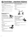
To Remove a Shelf:
• Slightly tilt up the
front and lift up the
rear of the shelf, then
pull the shelf straight
out.
To Lock the Shelf Into Another Position:
•Tilt up the front edge of the shelf.
• Insert the hooks into the desired frame openings and
let the shelf settle into place.
• Be sure the shelf is securely locked at the rear.
Elevator™ Shelf
The fresh food compartment is equipped with an
Elevator™ shelf.
This shelf can be adjusted up or down without having
to be unloaded of its contents. To adjust an Elevator™
shelf, pull out the knob on the crank handle. Rotate the
crank clockwise to raise the height of the shelf, and
counterclockwise to lower the height of the shelf.
To avoid personal injury or property damage,
observe the following:
• Never attempt to adjust a shelf that is loaded with
food (except in the case of the Elevator™ shelf).
• Confirm shelf is secure before placing items on
shelf.
• Handle tempered glass shelves carefully. Shelves
may break suddenly if nicked, scratched, or
exposed to sudden temperature change.
CAUTION
To Remove:
Completely unload the shelf and pull the shelf forward.
When the shelf stops, press up on the tabs located
underneath its outside edges, then continue pulling
forward, clear of the frame.
To Install:
Align the shelf to the frame and push it all the way
back. (There is no need to depress the tabs for
reinstallation).
In ordinary use, the Elevator™ shelf frame assembly
does not require removal. Though unlikely, and not
recommended, the correct removal procedure is as
follows:
To Remove:
• Unload the shelf completely.
• Remove glass shelf by pulling forward. When shelf
stops lift up and continue pulling forward.
• Manually move the two rear latches toward the shelf
center.
•While supporting the entire shelf and frame from
underneath, lift slightly and rotate the assembly
approximately 30° to allow the rear mechanism to
clear the vertical rear side rails.
•The entire assembly can then be moved forward and
clear of the refrigerator compartment.
To Install:
• Reverse the removal procedure. Be sure the shelf is
in a level position.
•When the sliding shelf is pushed to the rear, it will
reposition the rear latches to their correct operating
position.
Note
• Do not raise the shelf to the very top of the
vertical rails, as the shelf may become jammed.

16
Humidity-Controlled Crisper Drawers
The Crisper Drawers provide a higher humidity
environment for fresh fruit and vegetable storage.
Controls
The Crisper Controls regulate the amount of humidity
in the crisper drawer. Slide the control towards the
fruit setting when storing produce with outer skins.
Slide the control towards the vegetable setting when
storing leafy produce.
Note
•For best results, keep the crisper drawers tightly
closed.
To Remove:
•Pull drawer out to full extension. Tilt up front of
drawer and pull straight out.
To Install:
• Insert drawer into frame rails and push back into
place.
Fresh Food Features
The Crisper Top serves as the lower fresh food shelf.
To Remove the Crisper Top:
• Remove crisper drawers as indicated below.
•Place hand under the frame to push up the glass. Lift
glass out.
•Lift frame from refrigerator liner rails.
To Install:
• Repeat above instructions in reverse order.
Door Storage
Dairy Compartment
The Dairy Compartment provides
convenient door storage for
spreadable items such as butter
and margarine. This compartment can be moved to
different locations to accommodate storage needs. To
use the dairy compartment, raise the cover.
To Remove:
•Raise the cover, pull upward and tilt out.
To Install:
• Reverse above procedure.
Door Buckets
Door Buckets can be moved to meet
storage needs.
To Remove:
• Slide bucket up and pull straight
out.
To Install:
• Slide bucket in and down until firmly seated in the
door liner.
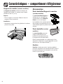
Full-width Door Shelf
Full-width Door Shelf removes for easy cleaning.
To Remove:
• Slide shelf up and pull
straight out.
To Install:
• Reverse above
procedure.
Storage Drawers
Snack Drawer (select models)
The Snack Drawer can be used for
storage of miscellaneous items or
extra produce.
To Remove:
•Pull drawer out to full extension. Tilt up front
of drawer and pull straight out.
To Install:
• Insert drawer into frame rails and push back into
place.

17
Fresh Food Features
Temperature-Controlled Drawer
(select models)
The Wide-N-Fresh™ deli drawer is a full-width drawer
with adjustable temperature control. This drawer can
be used for large party trays, deli items, beverages or
miscellaneous items.
There is a temperature control which adjusts the
amount of cold air allowed into the drawer. The
control is located on the right side of the drawer.
Depending on your model, it is either on the front of
the drawer or under the lid.
Set the control to cheese or to provide a normal
refrigerator temperature. Set the drawer on the
meats or setting when a temperature colder than
the main refrigerator compartment is desired. Use the
coldest setting when storing meats.
To Remove:
•Lift lid (select models). Pull drawer out to full
extension. Tilt up front of pantry and pull straight out.
To Install:
•Push metal glide rails to the back of the refrigerator
(select models). Place drawer onto rails and slide
drawer back until it falls into place.
Some models feature a divider to organize the drawer
into sections.
To Remove:
•Pull drawer completely out and raise the front of the
divider to unhook it from the rear wall of the drawer
and lift it out.
To Install:
• Hook back of divider over rear wall of the drawer and
lower into place.
Notes
• Cold air directed to the drawer can decrease
refrigerator temperature. Refrigerator control may
need to be adjusted.
• Do not place leafy vegetables in the drawer.
Colder temperatures could damage leafy produce.
Can Rack (select models)
The Can Rack slides out from
underneath the Spill-Catcher™
shelf. It holds up to twelve 12-
ounce beverage cans.
To Remove:
•Pull rack out to full extension. Tilt up the front of rack
and pull straight out.
To Install:
• Insert rack into frame rails and push back into place.
Accessories
Wine Trivet/Can Rack (select models)
The Wine Trivet/Can Rack
accessory fits in the Wide-N-
Fresh™ deli drawer or on a shelf.
Bottles or cans can be laid
crosswise, or a single bottle may be
laid in the center depression.
Wine Rack (select models)
The Wine Rack provides a place
for horizontally storing wine. The
rack can also hold an egg carton.
Position the rack to rest on the
left hand side of a refrigerator
shelf (this rack cannot be
positioned on an Elevator™ shelf).
Egg Cradle
The Egg Cradle (style may vary/select models) holds a
“dozen-plus” eggs. It can be removed to carry to work
area or to be washed.

Freezer Features
18
Automatic Ice Maker
(select models)
Note
• Energy rating guides that are posted on the
refrigerator at the time of purchase do not include
optional ice maker energy usage.
To avoid personal injury or property damage,
observe the following:
• Do not place fingers or hands on the automatic ice
making mechanism while the refrigerator is
plugged in. This will help protect you from possible
injury. It will also prevent interference with moving
parts of the ejector mechanism and the heating
element that releases the cubes.
• Under certain rare circumstances, ice cubes may
be discolored, usually appearing with a green-
bluish hue. The cause of this unusual discoloration
can be a combination of factors such as certain
characteristics of local waters, household
plumbing and the accumulation of copper salts in
an inactive water supply line which feeds the ice
maker. Continued consumption of such discolored
ice cubes may be injurious to health. If such
discoloration is observed, discard the ice cubes
and contact your dealer to purchase and install a
water line filter.
•Water damage due to improper water connection
may cause mold/mildew growth.
• Clean up wate and ice spills to avoid personal
injury and to prevent mold/mildew growth.
WARNING
Some models are automatic ice maker ready. The
number of the appropriate ice maker kit is IC11B. The
kit contains installation instructions and water
connection instructions.
Other models have a factory installed ice maker.
Connect the ice maker to the water supply as
instructed on page 10. Proper water flow and a level
refrigerator are essential for optimal ice maker
performance.
Operating Instructions
• Confirm ice bin is in place and ice maker arm is
down.
• After freezer section reaches
approximately 0° F (-18° C), ice
maker fills with water and begins
operating. You will have a complete
harvest of ice approximately every
three hours.
• Allow approximately 24 hours after installation to
receive first harvest of ice.
• Discard ice created within first 12 hours of operation
to verify system is flushed of impurities.
• Stop ice production by raising ice maker arm until
click is heard.
• Ice maker will remain in the off position until arm is
pushed down.
•The first one or two batches will probably contain
undersized and irregular cubes because of air in the
supply line.
•When the ice cubes are ejected it is normal for
several cubes to be joined together at the ends. They
can easily be broken apart. The ice maker will
continue to make ice until the supply of ice cubes
raises the sensor arm, shutting the ice maker off.
• Certain sounds may accompany the various cycles of
the ice maker. The motor may have a slight hum, the
cubes will rattle as they fall into an empty storage
pan and the water valve may click or “buzz”
occasionally.
• If the ice is not used frequently, the ice cubes will
become cloudy, shrink, stick together and taste stale.
Empty the ice storage bin periodically and wash it in
lukewarm water. Be sure to dry the bin thoroughly
before replacing it.
• Beverages and foods should not be placed in the ice
storage bin for quick chilling. These items can block
the sensor arm, causing the ice maker to
malfunction.
•Turn off (arm up) the ice maker when the water
supply is to be shut off for several hours.
To Remove the Ice Bin:
•Pull it forward, away from the ice maker. To avoid the
ice maker dumping ice while the bin is removed, turn
the ice maker off by raising the sensor arm.
To Install the Ice Bin:
• Reverse the above procedure. Turn the ice maker on
by lowering the sensor arm.

19
Freezer Features
Accessories
Ice Cube Tray (select models)
The Ice Cube Tray provides an area to freeze cubes
for manual dispensing of ice.
To release ice cubes from tray, hold tray
upside down over a storage container
and twist both ends of tray until
cubes release.
The Ice Service Rack (select
models) holds the ice cube tray.
To Install:
• Slide L-shaped groove of shelf
down over back wall screw.
Push rack back until screw is
stopped in L-shaped groove
(1). Slide front portion of shelf
over front wall screw (2).
To Remove:
•Perform above steps in reverse order.
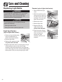
Shelves and Baskets
Models with swing freezer door:
Freezer Shelf (select models)
Select models have a shelf divider.
To Remove:
•Pull shelf out to full
extension. Tilt up front of
shelf and pull straight out.
To Install:
• Insert shelf into freezer liner rails and push to back
of compartment.
Wire Basket (select models)
To Remove:
•Pull basket out to full
extension. Tilt up front of
basket and pull straight out.
To Install:
• Insert basket into freezer liner rails and push back
into place.
Freezer Door Shelf (select models)
The Freezer Door Shelf provides
convenient storage for frozen food
items in freezer door.
To Remove:
•Lift shelf from side liner tabs and pull
out.
To Install:
• Fit ends of shelf on liner tabs and slide down.
1
2
2
1
Note
• Freezer Drawer Models: See page 5 for lower
basket and complete pullout drawer instructions.
Upper Wire Basket
To Remove:
•Pull upper basket out to full extension and lift out to
remove.
To Install:
•Slide upper basket into freezer. Make sure that rear
of basket hooks behind rail catch.
To prevent accidental child entrapment or
suffocation risk, do not remove the divider in the top
freezer basket.
DANGER
Models with pullout freezer drawer:
La page charge ...
La page charge ...
La page charge ...
La page charge ...
La page charge ...
La page charge ...
La page charge ...
La page charge ...
La page charge ...
La page charge ...
La page charge ...
La page charge ...
La page charge ...
La page charge ...
La page charge ...
La page charge ...
La page charge ...
La page charge ...
La page charge ...
La page charge ...
La page charge ...
La page charge ...
La page charge ...
La page charge ...
La page charge ...
La page charge ...
La page charge ...
La page charge ...
La page charge ...
La page charge ...
La page charge ...
La page charge ...
La page charge ...
La page charge ...
La page charge ...
La page charge ...
La page charge ...
La page charge ...
La page charge ...
La page charge ...
La page charge ...
La page charge ...
La page charge ...
La page charge ...
La page charge ...
La page charge ...
La page charge ...
La page charge ...
La page charge ...
La page charge ...
La page charge ...
La page charge ...
La page charge ...
La page charge ...
La page charge ...
La page charge ...
La page charge ...
La page charge ...
La page charge ...
La page charge ...
La page charge ...
La page charge ...
La page charge ...
La page charge ...
La page charge ...
La page charge ...
La page charge ...
La page charge ...
La page charge ...
La page charge ...
La page charge ...
La page charge ...
La page charge ...
La page charge ...
La page charge ...
La page charge ...
La page charge ...
La page charge ...
La page charge ...
La page charge ...
La page charge ...
La page charge ...
La page charge ...
La page charge ...
-
 1
1
-
 2
2
-
 3
3
-
 4
4
-
 5
5
-
 6
6
-
 7
7
-
 8
8
-
 9
9
-
 10
10
-
 11
11
-
 12
12
-
 13
13
-
 14
14
-
 15
15
-
 16
16
-
 17
17
-
 18
18
-
 19
19
-
 20
20
-
 21
21
-
 22
22
-
 23
23
-
 24
24
-
 25
25
-
 26
26
-
 27
27
-
 28
28
-
 29
29
-
 30
30
-
 31
31
-
 32
32
-
 33
33
-
 34
34
-
 35
35
-
 36
36
-
 37
37
-
 38
38
-
 39
39
-
 40
40
-
 41
41
-
 42
42
-
 43
43
-
 44
44
-
 45
45
-
 46
46
-
 47
47
-
 48
48
-
 49
49
-
 50
50
-
 51
51
-
 52
52
-
 53
53
-
 54
54
-
 55
55
-
 56
56
-
 57
57
-
 58
58
-
 59
59
-
 60
60
-
 61
61
-
 62
62
-
 63
63
-
 64
64
-
 65
65
-
 66
66
-
 67
67
-
 68
68
-
 69
69
-
 70
70
-
 71
71
-
 72
72
-
 73
73
-
 74
74
-
 75
75
-
 76
76
-
 77
77
-
 78
78
-
 79
79
-
 80
80
-
 81
81
-
 82
82
-
 83
83
-
 84
84
-
 85
85
-
 86
86
-
 87
87
-
 88
88
-
 89
89
-
 90
90
-
 91
91
-
 92
92
-
 93
93
-
 94
94
-
 95
95
-
 96
96
-
 97
97
-
 98
98
-
 99
99
-
 100
100
-
 101
101
-
 102
102
-
 103
103
-
 104
104


Maytag MBF1956HE Mode d'emploi
- Catégorie
- Congélateurs
- Taper
- Mode d'emploi
- Ce manuel convient également à
dans d''autres langues
- English: Maytag MBF1956HE User guide
- español: Maytag MBF1956HE Guía del usuario
Documents connexes
-
Maytag MCD2257HE Mode d'emploi
-
Maytag MCD2257HE Manuel utilisateur
-
-
Maytag ARB1905CB Manuel utilisateur
-
-
-
Maytag MBR2562KES Le manuel du propriétaire
-
-
-
Autres documents
-
Crosley CB19G6W Le manuel du propriétaire
-
Jenn-Air JFC2089HES Manuel utilisateur
-
Kenmore 596 . 66022700 Manuel utilisateur
-
Amana ABB1921DEQ Manuel utilisateur
-
Fisher & Paykel RX216CT4X2 Manuel utilisateur
-
-
 Kenmore Elite 59672283201 Le manuel du propriétaire
-
-
-
