
Use, Care, and Installation Guide
Guide d´utilisation, d´entretein et d´installation
Guía de instalación, uso y mantenimiento
READ AND SAVE THESE INSTRUCTIONS
LEA Y GUARDE ESTAS INSTRUCCIONES
LISEZ CES INSTRUCTIONS ET CONSERVEZ-LES

2
English
French
Spanish
Contents
Sommaire
Contenido
page
page
página
2
22
43
English
Important safety Notice.............................................................................................................................................3
Electrical & Installation requirements ....................................................................................................................4
Electrical requirements ........................................................................................................................................................................................ 4
Before installing the hood .................................................................................................................................................................................... 4
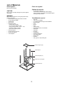
List of Materials.........................................................................................................................................................5
Parts supplied ..................................................................................................................................................................................................... 5
Parts not supplied ............................................................................................................................................................................................... 5
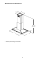
Dimensions and Clearances.....................................................................................................................................6
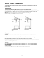
Ducting Options and Examples................................................................................................................................7
Venting methods.................................................................................................................................................................................................. .7
Preparation .......................................................................................................................................................................................................... 7
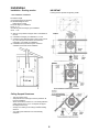
Installation ................................................................................................................................................................8
Installation - Ducting version................................................................................................................................................................................ 8
Installation - Ductless (Recirculating) version ................................................................................................................................................... 12
Description of the hood & Controls.......................................................................................................................16
Controls.............................................................................................................................................................................................................. 17
Maintenance ............................................................................................................................................................19
Cleaning............................................................................................................................................................................................................. 19
Grease Filter ...................................................................................................................................................................................................... 19
Replacing the light bulb...................................................................................................................................................................................... 19
Charcoal Filter.................................................................................................................................................................................................... 20
Warranty ...................................................................................................................................................................21
APPROVED FOR RESIDENTIAL APPLIANCES
FOR RESIDENTIAL USE ONLY
READ AND SAVE THESE INSTRUCTIONS
PLEASE READ ENTIRE INSTRUCTIONS BEFORE PROCEEDING.
INSTALLATION MUST COMPLY WITH ALL LOCAL CODES.
IMPORTANT: Save these Instructions for the Local Electrical Inspector’s use.
INSTALLER: Please leave these Instructions with this unit for the owner.
OWNER: Please retain these instructions for future reference.
Safety Warning: Turn off power circuit at service panel and lock out panel, before wiring
this appliance.
Requirement: 120 V AC, 60 Hz. 15 or 20 A Branch Circuit

3
READ AND SAVE THESE INSTRUCTIONS
Important safety Notice
CAUTION
FOR GENERAL VENTILATING USE ONLY. DO NOT USE
TO EXHAUST HAZARDOUS OR EXPLOSIVE
MATERIALS OR VAPOURS.
WARNING
TO REDUCE THE RISK OF FIRE, ELECTRIC SHOCK, OR
INJURY TO PERSONS, OBSERVE THE FOLLOWING:
Use this unit only in the manner intended by the
manufacturer. If you have questions, contact the
manufacturer.
Before servicing or cleaning the unit, switch power off
at service panel and lock service panel disconnecting
means to prevent power from being switched on
accidentally. When the service disconnecting means
cannot be locked, securely fasten a prominent warning
device, such as a tag, to the service panel.
Installation Work and Electrical Wiring Must Be Done By
QualiedPerson(s)InAccordanceWithAllApplicable
Codes & Standards, Including Fire-rated Construction.
Sufcientairisneededforpropercombustionand
exhaustingofgasesthroughtheue(Chimney)offuel
burning equipment to prevent back- drafting.
Follow the heating equipment manufacturers guideline
and safety standards such as those published by the
NationalFireProtectionAssociation(NFPA),
theAmericanSocietyforHeating,
RefrigerationandAirConditioningEngineers(ASHRAE),
and the local code authorities.
When cutting or drilling into wall or ceiling, do not
damage electrical wiring and other hidden utilities.
Ducted systems must always be vented to the outdoors.
CAUTION
To reduce risk of re and to properly exhaust air, be
sure to duct air outside - do not vent exhaust air into
spaces within walls, ceilings, attics, crawl spaces, or
garages.
WARNING
TO REDUCE THE RISK OF FIRE, USE ONLY METAL
DUCT WORK.
Install this hood in accordance with all requirements
specied.
WARNING
To Reduce The Risk Of Fire Or Electric Shock, Do Not
Use This Hood With Any External Solid State Speed
Control Device.
WARNING
TO REDUCE THE RISK OF A RANGE TOP GREASE
FIRE.
Never leave surface units unattended at high settings.
Boilovers cause smoking and greasy spillovers that may
ignite.Heatoilsslowlyonlowormediumsettings.
AlwaysturnhoodONwhencookingathighheator
whenambeingfood(I.e.CrepesSuzette,Cherries
Jubilee, Peppercorn Beef Flambe’).
Clean ventilating fans frequently. Grease should not be
allowedtoaccumulateonfanorlter.
Useproperpansize.Alwaysusecookwareappropriate
forthesizeofthesurfaceelement.
A.
B.
C.
D.
E.
F.
a)
b)
c)
d)
WARNING
TO REDUCE THE RISK OF INJURY TO PERSONS, IN
THE EVENT OF A RANGE TOP GREASE FIRE,
OBSERVE THE FOLLOWING:
SMOTHERFLAMESwithaclose-ttinglid,cookie
sheet, or other metal tray, then turn off the gas burner or
theelectricelement.BECAREFULTOPREVENT
BURNS.Iftheamesdonotgooutimmediately,
EVACUATEANDCALLTHEFIREDEPARTMENT.
NEVERPICKUPAFLAMINGPAN-youmaybe
burned.
DONOTUSEWATER,includingwetdishclothsor
towels - a violent steam explosion will result.
Use an extinguisher ONLY if:
YouknowyouhaveaclassABCextinguisher,and
you already know how to operate it.
Thereissmallandcontainedintheareawhereit
started.
Theredepartmentisbeingcalled.
Youcanghttherewithyourbacktoanexit.
OPERATION
a.Alwaysleavesafetygrillsandltersinplace.Without
these components, operating blowers could catch onto hair,
ngersandlooseclothing.
Themanufacturerdeclinesallresponsibilityintheeventof
failure to observe the instructions given here for installation,
maintenanceandsuitableuseoftheproduct.The
manufacturer further declines all responsibility for injury due
to negligence and the warranty of the unit automatically
expires due to improper maintenance.
a)
b)
c)
d)
1)
2)
3)
4)

4
Electrical & Installation requirements
Electrical requirements
IMPORTANT
Observeallgoverningcodesandordinances.
It is the customer’s responsibility:
Tocontactaqualiedelectricalinstaller.
Toassurethattheelectricalinstallationisadequateandin
conformancewithNationalElectricalCode,ANSI/NFPA70
—latestedition*,orCSAStandardsC22.1-94,Canadian
Electrical Code, Part 1 and C22.2 No.0-M91 - latest
edition** and all local codes and ordinances.
If codes permit and a separate ground wire is used, it is
recommendedthataqualiedelectriciandeterminethatthe
ground path is adequate.
Do not ground to a gas pipe.
Checkwithaqualiedelectricianifyouarenotsurerange
hood is properly grounded.
Do not have a fuse in the neutral or ground circuit.
IMPORTANT
Save Installation Instructions for electrical inspector’s use.
Therangehoodmustbeconnectedwithcopperwireonly.
Therangehoodshouldbeconnecteddirectlytothefused
disconnect(Orcircuitbreaker)boxthroughmetalelectrical
conduit.
WiresizesmustconformtotherequirementsoftheNational
ElectricalCodeANSI/NFPA70—latestedition*,orCSA
Standards C22.1-94, Canadian Electrical Code Part 1 and
C22.2 No. 0-M91 - latest edition** and all local codes and
ordinances.
AU.L.-orC.S.A.-listedconduitconnectormustbeprovided
at each end of the power supply conduit (at the range hood
and at the junction box).
Copies of the standards listed may be obtained from:
*NationalFireProtectionAssociationBatterymarchParkQuincy,
Massachusetts 02269
**CSAInternational8501EastPleasantValleyRoadCleveland,
Ohio44131-5575
Before installing the hood
Forthemostefcientairowexhaust,useastraightrun
or as few elbows as possible.
CAUTION: Vent unit to outside of building, only.
Atleasttwopeoplearenecessaryforinstallation.
Fittings material is provided to secure the hood to most
typesofwalls/ceilings,consultaQualiedInstaller,
checkiftheyperfectlytwithyourcabinet/wall.
Donotuseexducting.
COLDWEATHERinstallationsshouldhaveanadditional
backdraftdamperinstalledtominimizebackwardcoldair
owandanonmetallicthermalbreaktominimize
conduction of outside temperatures as part of the
ductwork.Thedampershouldbeonthecoldairsideof
the thermal break.
Thebreakshouldbeascloseaspossibletowherethe
ducting enters the heated portion of the house.
Makeupair:Localbuildingcodesmayrequiretheuseof
Make-UpAirSystemswhenusingDuctedVentilation
SystemsgreaterthanspeciedCFMofairmovement.
ThespeciedCFMvariesfromlocaletolocale.Consult
yourHVACprofessionalforspecicrequirementsinyour
area.
1.
2.
3.
4.
5.
6.

5
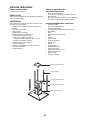
List of Materials
Parts supplied
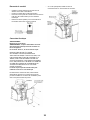
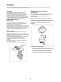
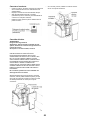
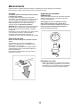
Removing the packaging
CAUTION!
Remove carton carefully, Wear gloves to protect against
sharp edges.
WARNING!
Removetheprotectivelmcoveringtheproductbefore
putting into operation.
Hoodstructureassemblywithblower,transition.
4Lampsalreadyinstalled.
3Greaselter
4 Duct covers.
Hardwarebagwith:
CeilingMountTemplate
Use, care and installation guide
Woodscrews(4pieces-3/16”x1”3/4)
Assemblyscrews(71pieces)
Duct cover brackets (4 each)
8 Vertical supports.
2 Upper Ductcover supports.
2Horizontalsupports.
2TorxAdapters.
•
•
•
•
•
•
•
•
•
•
•
•
•
•
Parts not supplied
Optional Accessories
Ductless Recirculating Kit
TobeusedonlyintheDuctless(Recirculating)
versionincludes:charcoallter,charcoalltersupport
andxingbracket,deector
Tools/Materials required
Wire nuts
Tapetomounttemplate
8”roundedmetalductlengthtosuitinstallation
Measuring tape
Pliers
Gloves
Knife
Safety glasses
Electricdrillwith5/16”and3/8”Bits
Strain relief
Spirit level
Duct tape
Screwdrivers:
Phillips (Posidrive) # 2
Wirecutter/stripper
Masking tape
Hammer
Saw, jig saw or reciprocating saw
•
•
•
•
•
•
•
•
•
•
•
•
•
•
•
•
•
•
•
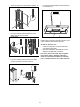
Horizontalsupport(sup)
Vertical support
Horizontalsupport(inf)
Vertical duct cover supports
Vertical support (inf)

6
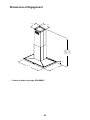
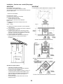
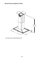
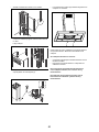
Dimensions and Clearances
Ductless (Recirculating) version ONLY•
* Mín 32 - 13/32”
*Max 52 - 13/32“
27”
2 - 3/8”
13 - 3/16”
12 - 1/8”
36” - 42”
** Mín 32 - 13/32”
** Max 46 - 13/32“

7
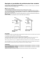
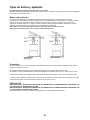
Ducting Options and Examples
Closely follow the instructions set out in this manual.
Allresponsibility,foranyeventualinconveniences,damagesorrescausedbynotcomplyingwiththeinstructionsinthis
manual, is declined.
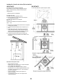
Venting methods
ThehoodisequippedwithatransitionB for discharge of fumes to the outside (Ducting version).
Should it not be possible to discharge cooking fumes and vapour to the outside, the hood can be used in the Ductless
(Recirculating) version.Attachacharcoallterandthedeector F on the duct cover support bracket G. Fumes and vapours
are recycled through the top grille H by means of a duct connected to the transition B and the transition mounted on the
deector
F.
NOTE: For ductless (Recirculating) version only: purchase the Ductless Recirculating Kit.
Minimum Duct Size (Ducting/Ductless version): 8” Round Pipe.
Preparation
Do not cut a joist or stud unless absolutely necessary. If a joist or stud must be cut, then a supporting frame must be
constructed.
Fittingsmaterialisprovidedtosecurethehoodtomosttypesofwalls/ceilings.
However,aqualiedtechnicianmustverifysuitabilityofthematerialsinaccordancewiththetypeofwall/ceiling.
Before making cutouts, make sure there is proper clearance within the ceiling or wall for exhaust vent.
Hoodinstallationheightabovecooktopistheuserspreference.Thelowerthehoodisabovethecooktop,themoreefcientthe
capturing of cooking odors, grease and smoke.
CAUTION:
FOR 8’ CEILINGS: MOUNT THIS HOOD SO THAT THE BOTTOM EDGE IS AT 27” (68,6 CM) MINIMUM ABOVE THE
COOKING SURFACE.
FOR 9’ CEILINGS: MOUNT THIS HOOD SO THAT THE BOTTOM EDGE IS AT 30” (76,2 CM) MINIMUM ABOVE THE
COOKING SURFACE.
Check your ceiling height and the hood height maximum before you select your hood.

8
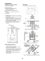
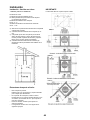
Installation
Installation - Ducting version
1. Pre-installation calculations
K = KitchenHeight
C = CounterHeight(36”standard)
P =PreferedHeightofHood
Bottom above counter
H = Hoodheightyourinstallation
H = K – C – P
S =ChimneyStructureHeight,yourinstallation.
S = H-1”3/8.
Select a hood preference height P that is comfortable for
the user.
CalculateHoodheightyourinstallationH=K-C-P.
ConrmthatHiswithintherangeofmintomaxHfound
foryourmodel(See“Dimensionsandclearances”
paragraph). If not adjust your installation.
Calculate Chimney structure height S. Save this
calculation for use later in the installation.
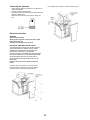
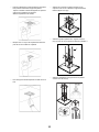
Ceiling Support Structures
Thisventhoodisheavy.
Adequatestructureandsupportmustbeprovidedinall
types of installations.
Atthehoodlocation,install2”x4”crossframingbetween
ceilingjoistsasshown.(2”x4”arerequiredtosupport
the weight of the hood.)
Arrangecrossframingintheceilingtosuit
the existing
structure.
Your ceiling joists will be like one of the following
examples.
a)
b)
c)
d)
•
•
•
•
•
IMPORTANT
Framing must be capable of supporting 150lbs.

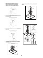
9
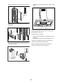
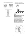
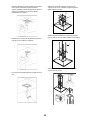
Place the template in the ceiling considering the
instructions for ceiling support structures.
Alwaysconsiderthefrontofhoodlegendwhen
playingthetempleteontheceiling.Itwilldenethe
control’s location.
Mark with a pencil the hole locations for screws and duct
in the ceiling.
Fixtheupperhorizontalsupportwith4woodscrews.
•
•
•
Attachthe4lowerverticalsupports(A)tothehood
with16screwsThenattachthelowerhorizontal
support (B) whit 8 screws (inf).
Attachthe4upperverticalsupports(sup)(c)whit16
screws to adjust he desired distance.
Attachtheassemblytothesupportxedontheceiling.
Assurewithscrews(16).
•
•
•
click!
A
B
C

10
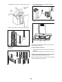
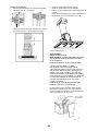
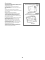
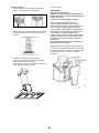
Connecting the ductwork
Install ductwork, making connections in the direction of
airowasillustrated.
Push duct over the exhaust outlet.
Wrapallductjointsandtheangeconnectionswithduct
tape for an airtight seal.
Make the same connection in the wall or ceiling vent
exit.
Electrical connection
WARNING
Electrical Shock Hazard
Warning: Turn off power circuit at the service panel
before wiring this unit.
120 VAC, 15 or 20 Amp circuit required.
ELECTRICAL GROUNDING INSTRUCTIONS
THISAPPLIANCEISFITTEDWITHANELECTRICAL
JUNCTIONBOXWITH3WIRES,ONEOFWHICH
(GREEN/YELLOW)SERVESTOGROUNDTHE
APPLIANCE.TOPROTECTYOUAGAINST
ELECTRICSHOCK,THEGREENANDYELLOWWIRE
MUSTBECONNECTEDTOTHEGROUNDINGWIRE
INYOURHOMEELECTRICALSYSTEM,ANDIT
MUSTUNDERNOCIRCUMSTANCESBECUTOR
REMOVED.
Failure to do so can result in death or electrical
shock.
Facing the front of the range hood, remove the left
knockout and the Junction box cover and install the
conduitconnector(cULuslisted)injunctionbox.
•
•
•
•
Ifnotalreadydone,install1/2”conduitconnectorinjbox.•

11
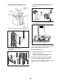
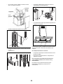
Attachtheverticalductcoversupportsusing4screws.
Place upper duct covers sliding through until spring
sounds“click”.
Thenverify.
Place lower duct covers using one plastic bracket at
each vertex (4 needed).
•
•
•
Thelowerductcovershallbesecuredtorangehoodby4
screws.
Installthegreaselterandturnpoweronatservicepanel.
Check operation of the hood.
If range hood does not operate:
Check that the circuit breaker is not tripped or the house
fuse blown.
Disconnect power supply. Check that wiring is correct.
Togetthemostefcientusefromyournewrangehood,
readthe“UseandCareInformation”section.
Keep your Installation Instructions and Use and Care
Guide close to range hood for easy reference.
•
•
•

12
Installation - Ductless (Recirculating) version
IMPORTANT
Recirculating kit sold separately.
Topurchaseit,pleasedialthefollowingtollfreenumber
1-888-732-8018andrequesttheKIT02198forislandhoods.
1. Pre-installation calculations
K=KitchenHeight
C=CounterHeight(36”standard)
P=PreferedHeightofHood
Bottom above counter
H=Hoodheightyourinstallation
H=K–C–P
S=ChimneyStructureHeight,yourinstallation.
S=H-1”3/8.
Select a hood preference height P that is comfortable for
the user.
CalculateHoodheightyourinstallationH=K-C-P.
ConrmthatHiswithintherangeofmintomaxHfound
foryourmodel(See“Dimensionsandclearances”
paragraph). If not adjust your installation.
Calculate Chimney structure height S. Save this
calculation for use later in the installation.
Ceiling Support Structures
Thisventhoodisheavy.
Adequatestructureandsupportmustbeprovidedinall
types of installations.
Atthehoodlocation,install2”x4”crossframingbetween
ceilingjoistsasshown.(2”x4”arerequiredtosupport
the weight of the hood.)
Arrangecrossframingintheceilingtosuittheexisting
structure.
Your ceiling joists will be like one of the following
examples.
a)
b)
c)
d)
•
•
•
•
•
IMPORTANT
FramingmustbecapableIMPORTANTofsupporting150lbs.

13
Place the template in the ceiling considering the
instructions for ceiling support structures.
Alwaysconsiderthefrontofhoodlegendwhen
playingthetempleteontheceiling.Itwilldenethe
control’s location.
Mark with a pencil the hole locations for screws and duct
in the ceiling.
Fixtheupperhorizontalsupportwith4woodscrews.
•
•
•
Attachthe4lowerverticalsupports(A)tothehood
with16screwsThenattachthelowerhorizontal
support (B) whit 8 screws (inf).
Attachthe4upperverticalsupports(sup)(c)whit16
screws to adjust he desired distance.
Attachtheassemblytothesupportxedontheceiling.
Assurewithscrews(16).
•
•
•
click!
A
B
C

14
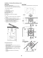
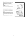
Air deector installation
Assembletheairdeectorwiththeupperhorizontal
support with 2 assembly screws.
Measurefromthebottomoftheairdeectortothebottom
of the hood outlet, as shown.
•
•
•
Cuttheductatthemeasuredsize.
Sliptheductontothebottomofthedeector.
Place the duct over the exhaust outlet from the hood.
Useducttapetosealthedeectorandattheexhaust
outlet from the hood.
Electrical connection
WARNING
Electrical Shock Hazard
Warning: Turn off power circuit at the service panel
before wiring this unit.
120 VAC, 15 or 20 Amp circuit required.
ELECTRICAL GROUNDING INSTRUCTIONS
THISAPPLIANCEISFITTEDWITHANELECTRICAL
JUNCTIONBOXWITH3WIRES,ONEOFWHICH
(GREEN/YELLOW)SERVESTOGROUNDTHE
APPLIANCE.TOPROTECTYOUAGAINST
ELECTRICSHOCK,THEGREENANDYELLOWWIRE
MUSTBECONNECTEDTOTHEGROUNDINGWIRE
INYOURHOMEELECTRICALSYSTEM,ANDIT
MUSTUNDERNOCIRCUMSTANCESBECUTOR
REMOVED.
Failure to do so can result in death or electrical
shock.
Facing the front of the range hood, remove the left
knockout and the Junction box cover and install the
conduitconnector(cULuslisted)injunctionbox.
•
•
•
•
•

15
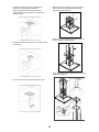
Ifnotalreadydone,install1/2”conduitconnectorinjbox.
Attachtheverticalductcoversupportsusing4screws.
Place upper duct covers sliding through until spring
sounds“click”.
Thenverify.
•
•
•
Place lower duct covers using one plastic bracket at
each vertex (4 needed).
Thelowerductcovershallbesecuredtorangehoodby4
screws.
Installthegreaselterandturnpoweronatservicepanel.
Check operation of the hood.
If range hood does not operate:
Check that the circuit breaker is not tripped or the house
fuse blown.
Disconnect power supply. Check that wirin g is correct.
To get the most efcient use from your new range hood,
read the “Use and Care Information” section.
Keep your Installation Instructions and Use and Care Guide
close to range hood for easy reference.
•
•
•
•

16
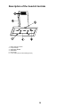
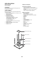
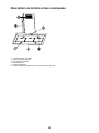
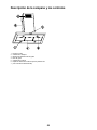
Description of the hood & Controls
Blower and light controls
Lamphousings
GreaselterHandle
Greaselter
Duct covers
Louverholes(OnlyforRecirculatingversion)
1.
2.
3.
4.
5.
6.

17
Controls
Use the high suction speed in cases of concentrated kitchen
vapours. It is recommended that the cooker hood suction is
switched on for 5 minutes prior to cooking and to leave in
operation during cooking and for another 15 minutes
approximately after terminating cooking.
Note:Hoodretainslastspeedsettingwhenaspiration
switch is turned off.
Description of control panel
1. Light Button
PresslampbuttontoturnONthelightonHigh
Intensity(LampstatepreviouslyOFF).
PresslampbuttontoturnONthelightonLow
Intensity(LampstatepreviouslyON).
PresslampbuttontoturnOFFthelight(Lampstate
previouslyON).
2. Timer Button
Thedefaulttimersettingis10minutes,anditcanbe
adjusted between 60 minutes and 1 minute.
Afterpressingthetimerbutton,thecontrolenterstoa
timer setup mode, and user can adjust the timer
countdowntimewiththe“+”and“-”buttonswithin5
seconds.Thetimercanbeinitiatedimmediately
pressing the timer button, after setting the timer
duration or pressing the timer button twice (default 10
minutes setting).
If no action occurs within 5 seconds, the countdown
will start.
Duringthetimersetupthe“+”and“-”buttonsare
dedicated to the timer and no motor action will occur.
Oncethetimerisinitiated,itcanbecancelledby
pressing the timer button again.
3. Display
Shows the hood settings.
Thedisplaywillbelitatlowintensitywhenthehood
is not operating.
Pressing any key the display will light up at high
intensity.
Thedisplaywillbelitathighintensitywhenthehood
is operating.
If no key is pressed within a minute the display will
return to being lit at low intensity.
4. “-” Button. Speed Decrease / OFF
Thisbuttonisusedtodecreasethefanspeed,or
turnOFFthefan.
ThefanwillturnOFFifthe“-”buttonispressedand
thehoodwasintherstspeed.
Ifthefanisatsecondspeedandthe“-”buttonis
pressed,thefanwillbesettorstspeed.
Ifthefanisatthirdspeedandthe“-”keyispressed,
the fan will be set to second speed.
Ifthefanisatfourthspeedandthe“-”buttonis
pressed, the fan will be set to third speed.
IfthefanisOFFandthe“-”buttonispressed,the
control backlight will light up.
•
•
•
•
•
•
•
•
•
•
•
•
•
•
•
•
•
5. “+” Button. Speed Increase / ON
Thisbuttonisusedtoincreasethefanspeed,orturn
ONthefan.
ThefanwillturnONifthe“+”buttonispressedand
thehoodwasOFF.
Ifthefanisatrstspeedandthe“+”buttonis
pressed, the fan will be set to second speed.
Ifthefanisatsecondspeedandthe“+”buttonis
pressed, the fan will be set to third speed.
Ifthefanisatthirdspeedandthe“+”buttonis
pressed, the fan will be set to fourth speed.
Ifthefanisatfourthspeedandthe“+”buttonis
pressed, a beep will sound.
Clock programming
Theclockcanbereprogrammedatanytimeexcept
during an active timed function.
Theclockcanbedisplayedinatwelvehourformatand
valid clock times are from 1:00 to 12:59.
Theclockcanbereprogrammedpressingthe“Timer”
button for 3 seconds, and after, the clock can be
adjustedwiththe“+”and“-”buttons.
Theusercanhaveminuteincrements/decrementsof1
minute,butiftheuserkeeppressingthe“+”/”-”buttons
formorethan1second,theincrements/decrementswill
be of 5 minutes.
During this option the control will round to the nearest 5
minutes.
Theusercannishonreprogrammingtheclockpressing
the“Timer”button.
After1minuteofnobuttonpressedthecontrolwill
accept the programmed clock time and will add one
minute to the set clock.
•
•
•
•
•
•
•
•
•
•
•
•

18
Greaseltersaturationalarm(Optional)
Afterthirtyfanfunctionalhours,thedisplaywillshow
“GreaseFilter”ifthefanisactive.
Whenthisiconisshowninthedisplay,thegreaselters
installed are required to be washed.
Toresetthegreaseltersaturationalarmtheusermust
pressthe“+”buttonfor5seconds,afterthisactionthe
icon“Greaselter”isnotdisplayed,andthehoodhas
the normal display operation.
Charcoalltersaturationalarm(Optional)
Afteronehundredandtwentyfunctionalhoursofthefan,
thedisplaywillshow“CharcoalFilter”ifthefanisactive.
Whenthisiconashesondisplay,thecharcoallters
installed are required to be replaced or reactivated.
Toresetthecharcoalltersaturationindicationtheuser
mustpressthe“-”buttonfor5seconds,afterthistime
theicon“Charcoallter”isnotdisplayedandthehood
has the normal display operation.
Audiblesignalactivationanddeactivation
Theaudiblesignalscanbeactivatedordeactivated
pressingthe“Light”buttonfor5seconds.
If the audible signal is activated, a tone must sound and
the“Snd”symbolmustappearonthedisplayfor3
seconds.
Iftheaudiblesignalisdeactivated,the“Snd”symbol
must appear on the display for 3 seconds and no tone
must sound.
Charcoallterinclusionandexclusion(Recirculating
accessories)
Thecharcoallterinclusionorexclusioncanbesetby
pressingthe“+”and“-”buttonsatthesametimefor5
seconds.
TheInclusionorexclusionofcharcoalltermustbe
selectedwhilethelampsandthemotorareOFF.
Whenthecharcoallterhasbeenexcluded,thecharcoal
lteralarmisdisabled.
Heatsensor
Thecontrolisequippedwithaheatsensorthatwillturn
on the blower at third speed if excessive heat occurs
(over 149° F or 65°C ) surrounding the control area.
IftheblowerisOFForifitisoperatingatrstspeed,the
blower will be set automatically to third speed, the
displayshowstheword“CArE“toindicatethatheat
sensor has detected an excessive heat.
During this state, the user may raise the blower speed to
fourth speed but can not decrease the speed.
When the temperature level on the hood drops to normal,
theblowerwilloperateinthesettingdenedbytheuser
before the alarm occured.
•
•
•
•
•
•
•
•
•
•
•
•
•
•

19
Cleaning
Do not spray cleaners directly to the control while
cleaningtheHood.Thecookerhoodshouldbecleaned
regularly (at least with the same frequency with which you
carryoutmaintenanceofthefatlters)internallyand
externally. Clean using the cloth dampened with neutral
liquiddetergent.Donotuseabrasiveproducts.DONOT
USE ALCOHOL!
WARNING:
Failure to carry out the basic cleaning recommendations of
thecookerhoodandreplacementoftheltersmaycause
rerisks.
Therefore,werecommendoservingtheseinstructions.
Themanufacturerdeclinesallresponsibilityforanydamage
tothemotororanyredamagelinkedtoinappropriate
maintenance or failure to observe the above safety
recommendations.
Grease Filter
Trapscookinggreaseparticles.
Thismustbecleanedonceamonthusingnonaggressive
detergents, either by hand or in the dishwasher, which must
be set to a low temperature and a short cycle. When
washedinadishwasher,thegreaseltermaydiscolour
slightly,butthisdoesnotaffectitslteringcapacity.
Toremovethegreaselter,pullthespringreleasehandle.
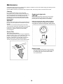
Replacing the light bulb
CAUTION
Before replacing the lamps, switch power off at service
panel and lock service panel disconnecting means to
prevent power from being switched on accidentally.
NOTE: Turn off the lights and fan. Allow the lights to
cool before handling. If new lights do not operate be
sure lights are inserted correctly before calling service.
Replace Lights
Remove the damaged light (twist counter clockwise)
and replace with a new 120 Volt, 50 Watt (maximum)
50° halogen light made for aGU10 base, suitable
use in open luminarie.
•
Maintenance
ATTENTION!Beforeperforminganymaintenanceoperation,isolatethehoodfromtheelectricalsupplybyswitchingoffatthe
connector and removing the connector fuse.
Oriftheappliancehasbeenconnectedthroughaplugandsocket,thentheplugmustberemovedfromthesocket.

20
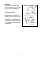
Charcoal Filter
If the model is not vented to the outside, the air will be
recirculatedthroughdisposablecharcoalltersthathelp
remove smoke and odors.
Thecharcoalltersareclippedonthemotorhousingframe.
NOTE: Charcoalltersarenotincludedwiththehood.
Theymustbeorderedfromyoursupplier.
Ordertheneededkitspecifyingyourhoodmodelandwidth
size.
Cleaning/replacing the charcoal lter
Unlikeothercharcoallters,theLONGLIFEcharcoallter
can be cleaned and reactivated.
Withnormalusetheltershouldbecleanedeverysecond
month (when using the hood 2.5 hours per day,on average).
Thebestwaytocleanthelterisinthedishwasher.Use
normal detergent and choose the highest temperature (65º
C or 149° F).
Washthelterseparatelysothatnofoodpartsgetsstuck
onthelterandlatercausesbadodours.
Toreactivatethecharcoal,theltershouldbedriedinan
oven for 10 minutes with a maximum temperature of 100º C
or 212° F.
Afterapproximatelyoneyearofuse,thecharcoallter
should be replaced with a new one, as the odour reduction
capacity will be reduced.
Motor
La page est en cours de chargement...
La page est en cours de chargement...
La page est en cours de chargement...
La page est en cours de chargement...
La page est en cours de chargement...
La page est en cours de chargement...
La page est en cours de chargement...
La page est en cours de chargement...
La page est en cours de chargement...
La page est en cours de chargement...
La page est en cours de chargement...
La page est en cours de chargement...
La page est en cours de chargement...
La page est en cours de chargement...
La page est en cours de chargement...
La page est en cours de chargement...
La page est en cours de chargement...
La page est en cours de chargement...
La page est en cours de chargement...
La page est en cours de chargement...
La page est en cours de chargement...
La page est en cours de chargement...
La page est en cours de chargement...
La page est en cours de chargement...
La page est en cours de chargement...
La page est en cours de chargement...
La page est en cours de chargement...
La page est en cours de chargement...
La page est en cours de chargement...
La page est en cours de chargement...
La page est en cours de chargement...
La page est en cours de chargement...
La page est en cours de chargement...
La page est en cours de chargement...
La page est en cours de chargement...
La page est en cours de chargement...
La page est en cours de chargement...
La page est en cours de chargement...
La page est en cours de chargement...
La page est en cours de chargement...
La page est en cours de chargement...
La page est en cours de chargement...
-
 1
1
-
 2
2
-
 3
3
-
 4
4
-
 5
5
-
 6
6
-
 7
7
-
 8
8
-
 9
9
-
 10
10
-
 11
11
-
 12
12
-
 13
13
-
 14
14
-
 15
15
-
 16
16
-
 17
17
-
 18
18
-
 19
19
-
 20
20
-
 21
21
-
 22
22
-
 23
23
-
 24
24
-
 25
25
-
 26
26
-
 27
27
-
 28
28
-
 29
29
-
 30
30
-
 31
31
-
 32
32
-
 33
33
-
 34
34
-
 35
35
-
 36
36
-
 37
37
-
 38
38
-
 39
39
-
 40
40
-
 41
41
-
 42
42
-
 43
43
-
 44
44
-
 45
45
-
 46
46
-
 47
47
-
 48
48
-
 49
49
-
 50
50
-
 51
51
-
 52
52
-
 53
53
-
 54
54
-
 55
55
-
 56
56
-
 57
57
-
 58
58
-
 59
59
-
 60
60
-
 61
61
-
 62
62


ELICA ESL636S3 Guide d'installation
- Catégorie
- Hottes
- Taper
- Guide d'installation
dans d''autres langues
- English: ELICA ESL636S3 Installation guide
- español: ELICA ESL636S3 Guía de instalación
Documents connexes
-
ELICA EVR630SS Mode d'emploi
-
-
-
-
ELICA EPL630S1 Le manuel du propriétaire
-
-
-
-
ELICA EGL430SS Guide d'installation
-