
HME# 400G788
Rev A 10/15/18
DX340ES EU
HD Wireless Headset System
Operating Instructions
HM ELECTRONICS, INC.
2848 Whiptail Loop, Carlsbad, CA 92010 USA
Phone: 1-800-848-4468 Fax: 858-552-0172
Website: www.hme.com Email: [email protected]


SECTION 1. INTRODUCTION...............................................................................1
Radio Communication Center . . . . . . . . . . . . . . . . . . . . . . . . . . . . . . . . . . . . . . . . . . . . . . . . . . . . . . . . . . . . . . . . . . . . . . . . . . . . . . . . . 1
Theater ..................................................................................................1
Broadcasting ..............................................................................................1
SECTION 2. EQUIPMENT IDENTIFICATION ...................................................................2
STANDARD EQUIPMENT ......................................................................................2
OPTIONAL EQUIPMENT .......................................................................................3
EQUIPMENT FEATURES.......................................................................................4
Base Station ..............................................................................................4
Beltpac...................................................................................................6
All-in-One Headset (optional) .................................................................................6
SECTION 3. EQUIPMENT SETUP ...........................................................................7
BATTERY CHARGER..........................................................................................7
BASE STATION ..............................................................................................8
Optional Battery Operation of Base Station.......................................................................9
SECTION 4. FREQUENCY INTERFERENCE AVOIDANCE.......................................................10
ADAPTIVE FREQUENCY HOPPING .............................................................................10
Background . . . . . . . . . . . . . . . . . . . . . . . . . . . . . . . . . . . . . . . . . . . . . . . . . . . . . . . . . . . . . . . . . . . . . . . . . . . . . . . . . . . . . . . . . . . . . . 10
Operation in Severe Environments ...............................................................................11
Interference Mitigation . . . . . . . . . . . . . . . . . . . . . . . . . . . . . . . . . . . . . . . . . . . . . . . . . . . . . . . . . . . . . . . . . . . . . . . . . . . . . . . . . . . . . . . . 11
Required AFH Equipment ......................................................................................11
Non-AFH Equipment..........................................................................................11
MULTI-BASE INTERFERENCE AVOIDANCE ......................................................................12
Active (Manual) Secondary Base Sync .........................................................................12
Power Cycle / Reset .......................................................................................12
Passive (Automatic) Sync ...................................................................................13
Power Cycle / Reset .......................................................................................13
Beltpacs.................................................................................................14
Clear All Registration .......................................................................................14
DX SERIES LED AID .........................................................................................14
SECTION 5. MULTIPLE BASE STATIONS ....................................................................16
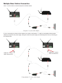
Audio Connection .........................................................................................16
Single/Dual Channel Setting .................................................................................16
Base Station Microphone Gain Adjustment ......................................................................16
Multiple Base Station Connection .............................................................................17
SECTION 6. REGISTRATION ..............................................................................18
Beltpac and All-in-one Headset ...............................................................................18
Beltpac or All-In-One Headset Adjustments......................................................................19
SECTION 7. EQUIPMENT OPERATION ......................................................................20
THE BASICS................................................................................................20
Base Station Operation . . . . . . . . . . . . . . . . . . . . . . . . . . . . . . . . . . . . . . . . . . . . . . . . . . . . . . . . . . . . . . . . . . . . . . . . . . . . . . . . . . . . . 20
Beltpac / All-In-One Headset Operation.........................................................................21
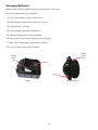
Changing Batteries ........................................................................................22
Beltpac or All-In-One Headset Operating Mode Setup .............................................................23
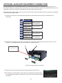
OPTIONAL AUXILIARY EQUIPMENT CONNECTION ................................................................24
OPTIONAL REMOTE ANTENNA INSTALLATION ...................................................................25
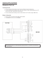
RADIO APPLICATIONS .......................................................................................26
Emergency Services .......................................................................................26
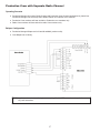
Production Crew with Separate Radio Channel ..................................................................27
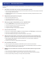
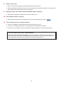
SECTION 8. TROUBLESHOOTING .........................................................................28
FREQUENTLY ASKED QUESTIONS .............................................................................30
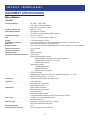
SECTION 9. TECHNICAL DATA ............................................................................31
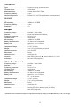
EQUIPMENT SPECIFICATIONS ................................................................................31
Base Station .............................................................................................31
Beltpac..................................................................................................32
All-In-One Headset ........................................................................................32
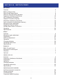
SECTION 10. SECTION INDEX.............................................................................33
SECTION 11. GENERAL BATTERY SAFETY INSTRUCTIONS FOR BATTERY MODEL BAT41, BAT50, BAT60 ............34
English..................................................................................................34
French . . . . . . . . . . . . . . . . . . . . . . . . . . . . . . . . . . . . . . . . . . . . . . . . . . . . . . . . . . . . . . . . . . . . . . . . . . . . . . . . . . . . . . . . . . . . . . . . . . 35
Spanish .................................................................................................36
Korean ..................................................................................................37
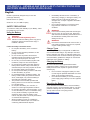
TABLE OF CONTENTS

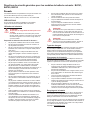
FCC NOTICE
This device complies with Part 15 of the FCC rules. Operation is subject to the following two conditions:
(1) This device may not cause harmful interference, and (2) This device must accept any interference received, including
interference that may cause undesired operation.
NOTE: This equipment has been tested and found to comply with the limits for a Class A digital device, pursuant to Part 15
of the FCC rules. These limits are designed to provide reasonable protection against harmful interference when the equipment
is operated in a commercial environment. This equipment generates, uses and can radiate radio frequency energy and, if
not installed and used in accordance with the instruction manual, may cause harmful interference to radio communication.
Operation of this equipment in a residential area is likely to cause harmful interference, in which case the user will be required
to correct the interference at his own expense.
Changes or modications not expressly approved by HM Electronics, Inc. could void the users authority to operate this
equipment.
Hereby, Clear-Com, LLC, an HM Electronics, Inc, company, declares that the DX340ES is in compliance with the essential
requirements and other relevant provisions of the RED (Radio Equipment Directive). In AFH mode, complies with European
Telecommunications Standards Institute (ETSI) harmonized European standard EN 300 328.
This product operates in the 2400 to 2483.5 MHz frequency range. The use of this frequency range is not yet harmonized
between all countries. Some countries may restrict the use of a portion of this band or impose other restriction relating to power
level or use. You should contact your Spectrum authority to determine possible restrictions.
WASTE ELECTRICAL AND ELECTRONIC EQUIPMENT (WEEE)
The European Union (EU) WEEE Directive (2012/96/EU) places an obligation on producers (manufacturers, distributors and/or
retailers) to take-back electronic products at the end of their useful life. The WEEE Directive covers most HME products being
sold into the EU as of August 13, 2005. Manufacturers, distributors and retailers are obliged to nance the costs of recovery
from municipal collection points, reuse, and recycling of specied percentages per the WEEE requirements.
Instructions for Disposal of WEEE by Users in the European Union
The symbol shown below is on the product or on its packaging which indicates that this product was put on the market after
August 13, 2005 and must not be disposed of with other waste. Instead, it is the user’s responsibility to dispose of the user’s
waste equipment by handing it over to a designated collection point for the recycling of WEEE. The separate collection and
recycling of waste equipment at the time of disposal will help to conserve natural resources and ensure that it is recycled in
a manner that protects human health and the environment. For more information about where you can drop off your waste
equipment for recycling, please contact your local authority, your household waste disposal service or the seller from whom you
purchased the product.
HM Electronics, Inc. is not responsible for equipment malfunctions due to erroneous
translation of its publications from their original English version. Illustrations in this
publication are approximate representations of the actual equipment, and may not be exactly
as the equipment appears.
© 2018 HM Electronics, Inc.
The HME logo and product names are registered trademarks of HM Electronics, Inc. All rights reserved.

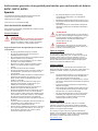
MANDATORY SAFETY INSTRUCTIONS FOR INSTALLERS AND USERS
Use only manufacturer or dealer supplied antennas, power supplies, batteries and battery chargers. All products are compliant with
regulatory requirements when installed correctly per Clear-Com installation instructions. The Federal Communications Commission has
adopted a safety standard for human exposure to RF (Radio frequency) energy, which is below the OSHA (Occupational Safety and Health
Act) limits.
Base Station Antenna minimum safe distance: 7.9 inches (20 cm) at 100% duty cycle.
Base Station Antenna gain: This device has been designed to operate with an antenna having a maximum gain of up to 7dBi.
Antenna mounting: The antenna(s) used for the base transmitter must be installed to provide a separation distance of at least 7.9 inches (20
cm) from all persons and must not be co-located or operating in conjunction with any other antenna or transmitter.
Antenna substitution: Do not substitute any antenna for the one supplied by the manufacturer. You may be exposing person or persons to
excess radio frequency radiation. You may contact your dealer or the manufacturer for further instructions.
WARNING: Maintain a separation distance from the base station transmit antenna to a person(s) of at least 7.9 inches (20 cm) at 100% duty
cycle.
WARNING: Excessive sound pressure level from earphones or headphones can cause hearing loss. You, as the qualied end-user of this
radio device must control the exposure conditions of bystanders to ensure the minimum separation distance (above) is maintained between
the antenna and nearby persons for satisfying exposure compliance. The operation of this transmitter must satisfy the requirements of
Occupational /Controlled Exposure Environment, for work-related use. Transmit only when person(s) are at least the minimum distance
from the properly installed, externally mounted antenna.
Canada IC Notice to Users English/French in accordance with RSS GEN
This device complies with Industry Canada license-exempt RSS standard(s). Operation is subject to the following two conditions: (1)
this device may not cause interference, and (2) this device must accept any interference, including interference that may cause undesired
operation of the device.
Cet appareil est conforme avec Industrie Canada RSS standard exempts de licence (s). Son utilization est soumise à Les deux conditions
suivantes: (1) cet appareil ne peut pas provoquer d’interférences et (2) cet appareil doit accepter Toute interférence, y compris les
interférences qui peuvent causer un mauvais fonctionnement du dispositif.

1
SECTION 1. INTRODUCTION
The DX340ES is a digital wireless communication system that enables hands-free two-way secure communication on
two independent channels, or both channels at the same time. It can be operated with AC or battery power. Multiple base
stations can be interconnected for expanded capabilities.
In addition to the standard communication among base station and beltpac operators, the system can be congured to
operate with almost any radio or digital matrix (4-Wire) communication system.
This manual provides detailed setup and operating instructions for your DX340ES system.
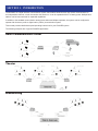
The following examples are of typical DX340ES applications.
Radio Communication Center
Theater
Broadcasting

2
SECTION 2. EQUIPMENT IDENTIFICATION
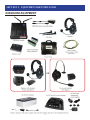
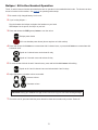
STANDARD EQUIPMENT
(shielded)

3
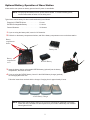
Headset with dual ear muffs
Model # CC-30-MD4
Headset, all-in-one, with battery
Model # WH340
Headset extension cable, 6 ft (1.83 meter) Foam earmuffs for all-in-one headset
Rechargeable battery for base station Model #
BAT850
Battery charger for base station batteries
Model # AC850
Remote antenna kit with 6 foot (1.83 meter) cable and
bracket
Remote antenna kit with 30 foot (9.14 meter) cable
and bracket
Adapter cable for headset with dynamic microphone
and XLR connector
Model # MD-XLR4F, MD-XLR4M, MD-XLR5F
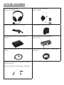
OPTIONAL EQUIPMENT

4
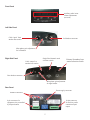
EQUIPMENT FEATURES
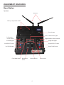
Base Station
Top Panel
Antennas
Battery compartment latches
Power button
Right talk lights
Left talk lights
Right SELECT buttonLeft SELECT button
Right TALK button
Left TALK button
Active communicator lights
Clear/Band button
Status indicator
Reset switch
Registration
button
Right headset volume control
Left headset
volume control

5
Front Panel
Left Side Panel
Right Side Panel
Microphone gain adjustment
for left headset
Cable “input” from
another base station
Auxiliary audio in/out
volume adjustments
(recessed)
Left headset connector
Rear headset connector
Single/Dual channel mode
selection switch
Cable “output” to
another base station
Primary/Secondary base
station selection switch
Microphone gain adjustment
for right headset
Rear Panel
10-pin connector
for auxiliary audio
connection input/
output
Antenna connectors
Power supply connector
8-pin connector for
equipment relay controlled
by beltpac buttons

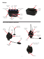
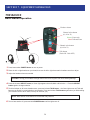
6
Beltpac
All-in-One Headset (optional)
Battery
release
latch
Battery
X-channel
button
All
button
O-channel
button
Power
button
Volume Up
button
Volume Down
button
Headset cable
connector
Power/O-channel
light
Power/X-channel
light
Headband
slide-to-t
Sanitary muff
Microphone
boom
Power/
Talk light
Power
button
Talk
light
X-channel
button
All
button
O-channel
button
Volume Up
button
Volume Down
button
Battery release latch
(blue button)
Battery

7
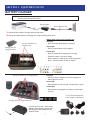
SECTION 3. EQUIPMENT SETUP
BATTERY CHARGER
NOTE: Set up the battery charger and charge all beltpac and/or all-in-one headset batteries while
you are setting up the base station.
Power Supply
Power Supply Cord
1 Connect power supply to charger and electrical outlet.
2 Charge all beltpac batteries. Charging time is approximately three hours.
Put up to 4 batteries in charging ports
Put up to 4 batteries in
charging ports
Storage ports for
charged batteries
Status lights next to each charging port
Red light
• Stays on steady while battery is charging
Green light
• Goes on when battery is fully charged
Yellow light
• Stays on steady when charging port is empty
• Flashes if battery is too hot to charge
• Next to battery in charging port means charge has
failed – see instructions on side of charger
Red light
• When you place a battery in a port for charging, its
status light will turn red.
Green light
• When a battery is fully charged, its status light is green.
Yellow light
• When a battery charging port is empty, its status light
is yellow.
Storage ports for charged batteries
Plug the cord from the +5VDC power
adapter into the battery charger, and
then plug the power adapter into an
electrical outlet.
AC50 US and international
power supplies and adapters

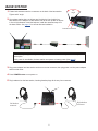
8
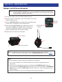
BASE STATION
1 Fasten both antennas onto the connectors on the back of the base station.
Tighten at 90° angle.
2 Set up base station where no objects are blocking the line-of-sight from
base station to the beltpacs. If base station can not be set up with no objects
in line-of-sight between it and the beltpacs, install the antennas away from
the base station. See page 27 for remote antenna installation.
Antenna connectors
90°
angle
NOTE: A fully charged battery can be kept in the base station as a backup in case of AC power
interruption.
If AC power is unavailable, the base station can operate on battery power (See page 9).
3 Plug power adapter into base station and screw nut onto connector, then plug power cord into power adapter
and electrical outlet.
4 Press POWER button to turn power on.
5 Plug headsets into the base station, inserting headset plugs all the way into connectors.
Left headset
connector
Right headset
connector

9
Optional Battery Operation of Base Station
A base station can operate on battery power when AC power is unavailable.
Typical base station battery life when used continuously is as follows:
Energizer ULTIMATE Lithium ................5 hours
BAT850 Rechargeable Battery ...............2¼ hours
Duracell Quantum .........................35 minutes
1 If you are using the battery sled, insert six “AA” batteries.
2 Pull back on the battery compartment latches, and lift the battery compartment cover on the base station.
NOTE: Always plug base station into AC power when available. To conserve battery power,
turn the base station off when it is not being used.
NOTE: When base station battery power is low, everyone connected or registered to that base
station will hear a headset tone that repeats every 8 seconds. Additionally, both headset
select lights will blink.
BAT850 Battery
Battery sled
3 Insert the battery sled or rechargeable BAT850 battery (optional) into the battery
compartment, and close the cover.
4 If you are using the BAT850 battery, insert it in the AC850 battery charger (optional)
for recharging after each use.
Follow the instructions received with the charger. Charging time is approximately 3 hours.
AC850 Battery Charger
Battery
compartment
cover
Battery
compartment
latches

10
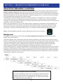
ADAPTIVE FREQUENCY HOPPING
In order to reduce interference with other equipment and comply with these new regulations, HME has implemented an
Adaptive Frequency Hopping (AFH) mode for the new DX EU base stations. The key idea behind AFH is using only
the good frequencies, or channels, unoccupied by other equipment. The system scans for other signals and avoids these
signals during operation. Since the radio environment is constantly changing, there is a continuous process of scanning
for used frequencies and updating the list of good channels.
The HME system utilizes 46 discrete frequencies, or channels, within the 2.4 GHz spectrum in order to communicate
voice and data. The process of deciding which channels should be used is a 3-stage process. The process includes
scanning for occupied channels, the broadcast of a channel exclusion list and the use of the exclusion list. The process is
completed in three steps coexisting in time.
Below is the process shown in Time. First, the system performs a channel scan to determine occupied channels. This
list is then broadcast to the communicator. The communicators and base station will use this list during period three.
The process is continuous, and as is illustrated below, the list could be constantly changing. Depending on the radio
environment, a maximum of 46 channels, and a minimum of 15 channels may be used by the system at any time.
AFH (
E
) - (European Mode) Advanced Frequency Hopping searches for the best frequency.
Background
The HME DX wireless intercom systems utilize a Frequency Hopping Spread Spectrum (FHSS) radio in order to
provide robust communications.
This system operates in the unlicensed 2.4 GHz band. With the proliferation of other devices over the past few years in
the same 2.4 GHz band, instances where these devices and systems can interfere with each other has greatly increased.
To further complicate matters, the European Union has introduced new radio standards for equipment operating
in this band in an attempt to reduce interference between equipment from different manufacturers. This European
Telecommunications Standards Institute (ETSI) harmonized European standard is known as EN 300 328.
Hereby, HM Electronics, Inc., declares that DX340ES is in compliance with the essential requirements and other relevant
provisions of “Radio Equipment Directive (RED). In AFH mode, DX340ES complies with European Telecommunications
Standards Institute (ETSI) harmonized European standard EN 300 328. Customers, Distributors or Installers operating in
a CE regulated country that switch off or disable AFH will render the product non-compliant with the directive and will be
considered the manufacturer of the product.
EU Bases are shipped in the AFH (E-mode)
Do not tamper with the AFH mode if you are operating in a region that requires
compliance with ETSI EN300 328. Changes and modications not expressly
approved by Clear-Com, LLC an HM Electronics, Inc. company could void the
user’s authority to operate this equipment.
SECTION 4. FREQUENCY INTERFERENCE AVOIDANCE

11
Operation in Severe Environments
During normal operation, the fact that the system is constantly changing the channel list in use is transparent to the
user. It is possible, however, that in an environment with severe interference that the system may experience a slight
degradation. The Clear-Com system will use a minimum of 15 channels. If the environment is very crowded and less
than 15 channels are truly available, there could be increased radio ‘packet loss’ due to the high interference. The
following symptoms may be observed with AFH systems in a highly congested radio environment:
● This may result in system ‘busy’ indications. Channel lists are updated every few seconds, and in a severe
environment it is possible that these lists get missed by the communicator.
● Slight degradation in audio delity between the headsets and base station. This would be due to the same
symptom as the ‘busy’ indications. The HD audio processing is tolerant to this condition, which is why the
degradation may only be slight.
● Longer times to register. Registration may take longer, since the headset has to acquire the channel list from the
base station. If the base station has excluded a lot of channels, this takes longer as the communicator does not
have the exclusion list and looks for the base on channels it is not using.
● Initial sync time increase. For the same reason registration may take longer, the initial headset sync on power up
may take longer.
Interference Mitigation
Certain techniques can be used in an attempt to mitigate interference between different equipment in the 2.4 GHz
spectrum. Some of these are:
● Physical separation. If possible, equipment operating in the 2.4 GHz spectrum should be operating as far as
physically possible from the HME base station. A Wi-Fi access point or router is a common piece of equipment
that could interfere with the DX340ES system, or vice versa. These two pieces of equipment in particular should
not be located close together.
● Spectral separation. Most Wi-Fi access points allow the administrator to set the channel and bandwidth that
system operates on. Some systems employ an ‘auto’ mode, in which the Wi-Fi access point will automatically
selected the channel. With Wi-Fi access points, it is sometimes advantageous to manually select a channel
number to keep the Wi-Fi transmission at a xed location.
● Spectral efciency. Wi-Fi systems employ a standard sometimes referred to as 802.11. The number “11” is
simply the number given to the standard by the Institute of Electrical and Electronics Engineers (the IEEE).
Modern Wi-Fi routers will allow operation employing the 802.11n mode. This mode will allow higher data rates,
but it also may consume twice the number of radio channels. If the Wi-Fi router is set to 802.11n mode, it is best
to limit Wi-Fi bandwidth to 20 MHz.
● Alternate band selection. While most Wi-Fi systems operate at 2.4 GHz, which is the same band as the
DX340ES system. Most allow operation at 5 GHz. If possible, move any Wi-Fi access points and equipment to 5
GHz. This of course requires all Wi-Fi equipment to be 5 GHz capable, and most older equipment may only allow
2.4 GHz operation. Selection of 5 GHz may also not be desirable if the Wi-Fi network is for customer access.
Required AFH Equipment
AFH capable headsets and belt packs will have the letters ‘AFH’ labeled on the belt pack and headsets.
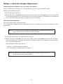
Non-AFH Equipment
Headsets and belt packs that are not AFH capable must be operated with either a non-AFH base station. Headsets and
belt packs that are not AFH capable will not have the letters ‘AFH’.

12
MULTI-BASE INTERFERENCE AVOIDANCE
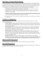
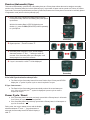
Active (Manual) Secondary Base Sync
This setup allows up to three Secondary bases to be manually placed in sync status numbers
1
,
2
or
3
respectively. After
synchronization, the Secondary base is set to avoid frequency hopping collision.
To sync the bases, perform the following steps to the Secondary base:
1 On the side of the intended Secondary base, move the
Primary/Secondary switch to Secondary (SEC) then power up
the base.
With the Secondary Base’s STATUS displaying two dashes
(
=
), press the REG (REGISTER) button repeatedly to cycle
number options.
Secondary
2 Select number
1
,
2
or
3
. During the initial search for a Primary
base, the Secondary searches for one 40 second period.
3 As the Secondary base searches, press the REG button on
the Primary base station. The selected number will ash.
Primary
4 If synchronization is successful, the Secondary base will
display a solid
1
,
2
or
3
.
Secondary
If the Initial Synchronization attempt fails...
● The Active Sync Secondary base will become unsynchronized Primary and STATUS will display
three dashes (
X
). A power cycle or reset is required to re-sync.
If Sync Loss occurs...
● The Active Sync Secondary base will automatically attempt a re-sync for one 60 second period. If the re-sync
fails, three dashes (
X
) will be displayed. A power cycle or reset is required to re-sync.
Power Cycle / Reset
If required to initially sync or re-sync the Secondary base with the Primary, power cycle the
Secondary base or use a paper clip (or like object) to press the RESET button.
● If the Secondary base has never previously synced with a Primary base, it will search
for a Primary for 40 seconds.
● If the Secondary base has previously synced with a Primary base, it will attempt a re-
sync for 60 seconds.

13
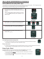
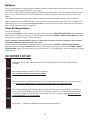
Passive (Automatic) Sync
This method automatically synchronizes a Secondary base to a Primary base without the need to assign a secondary
number to the Secondary base [as in Active (Manual) sync]. Any number of bases can be synced to a Primary in Passive
Sync mode. The normal synchronization process is performed, however the Primary does not need to be manually placed
in registration mode [as in the Active (manual) sync].
1 On the side of the intended Secondary base, move the
Primary/Secondary switch to Secondary (SEC) then power
up the base.
With the Secondary Base’s STATUS displaying two
dashes (
=
), press the REG (REGISTER) button repeatedly
to cycle options.
Secondary
2 Bypass options
1
,
2
and
3
to select "
P
”.
3 Secondary base will begin to sync, and the display
alternates between “
P
” and “
_
”. Initial sync takes 40
seconds. If the Secondary base sync fails again, it will
attempt again for a second 40 seconds.
4 If sync is successful, a solid “
P
” will be displayed.
Secondary
If the Initial Synchronization attempt fails...
● The Passive Sync Secondary base will become Passive Sync Primary and STATUS
display the “
J
” symbol. A power cycle or reset is required to re-sync.
If Sync Loss occurs...
● The Passive Sync Secondary base automatically make a 60 second attempt to
sync. If the re-sync fails, the “
J
” symbol is displayed. A power cycle or reset is
required to re-sync.
Power Cycle / Reset
● If the Secondary base has never previously synced with a Primary base, it will search
for a Primary for up to two 40 second periods.
● If the Secondary base has previously synced with a Primary base, it will attempt a re-
sync for 60 seconds.
During reset, the re-sync attempt occurs and the display
alternates between "
P
” and “
_
”. If synchronization is
achieved, the Secondary base STATUS will display a
solid “
P
”.

14
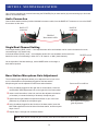
Beltpacs
During synchronization or re-synchronization, beltpacs cannot be used for audio communication. A blinking red LED will
be displayed. Voice prompt will announce “out of range”.
After sync or re-sync, beltpacs already registered to the Base, will automatically re-link with the Base, whether the Base
sync or re-sync was successful or not. After registration or re-linking, the beltpac number will blink three times on the
display.
New beltpacs can always be registered to a Base, regardless of the operating mode: Primary, Active or Passive.
Note: In situations where an HME EOS base is close by, the DX340 may passively synchronize to the EOS base if it is
within radio range. If not, follow the Clear All Registration process detailed below. Power off all other potential Primary
bases, and re-synchronize the Secondary base.
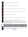
Clear All Registration
To clear all registration:
Hold down the CLR/BND or insert a paper clip (or like device) to press the RESET REGISTRATION* button rst and then
power the base on when you see the "
8
” on the LED display release the CLR/BND or RESET REGISTRATION*. If done
successfully you will see a small "c” on the LED display.
NOTE: The display indicates that the registry of a base station has been cleared of all beltpacs and Secondary
base stations that were registered to the base station.
Another method to clear the registry would be to start by holding down the CLR/BND or RESET REGISTRATION*
button rst and then pressing the RESET button until you hear a small click and then release the CLR/BND or RESET
REGISTRATION* button. If done successfully you will see a small “c” on the LED display. We recommend you use a very
small paper clip.
DX SERIES LED AID
Powering on any DX base station will produce on the LED display the number "
8
” for approximately
3 seconds.
Blank display indicates the base is ready for operation.
You can register belt packs under this condition.
Two horizontal bars (
=
) indicate that the base is in secondary mode and ready to be synced with a primary
base. You cannot register beltpacs in this mode you must sync to a primary base rst.
Three horizontal bars (
X
) indicate Active Sync Secondary base has either failed to register to a Primary, or
that an Active Sync Secondary base has lost synchronization to the Primary. It takes a few seconds for the
secondary to recognize that the primary is not available and revert to a primary state. However, you can
register belt packs under this condition.
The number “
1
” indicates the quadrant the secondary has been placed in.

15
The "
P
” indicates the Secondary base has successfully synchronized to a Primary base in Passive Sync.
The “
J
” symbol indicates that a second Passive Sync attempt has failed and is now set to normal Primary.
Displayed for 0.5 seconds to indicate radio has started.
The letter "
F
” will appear when the base registry is at its maximum of 15 registered beltpacs. You will need to
clear the registry to add a beltpac. See Clear All Registration, pg. 16.
The lower case “
c” will appear when the registry on the base station is cleared. To clear the registry power
down the base.
The lower case "
o
” will appear when the REG or REGISTER BELT-PAC* button is pressed and indicates that
the base is ready to register a beltpac.
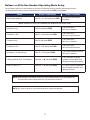
When registering beltpacs on DX bases that can carry 15 beltpacs please note that the numeric count
displayed on the LED will be in hexadecimal. This means that the LED will represent the rst 10 beltpacs as 0
to 9. Beltpac 11 will be represented by the letter (A), beltpac 12 will be represented by the letter (B) and on up
to beltpac 15 as (E). Please see below.
Beltpac
1 2 3 4 5 6 7 8 9 10 11 12 13 14 15
Registry
0 1 2 3 4 5 6 7 8 9 A B C D E
The number "
2
” indicates the quadrant the secondary has been placed in.
The number "
3
” indicates the quadrant the secondary has been placed in.
La page est en cours de chargement...
La page est en cours de chargement...
La page est en cours de chargement...
La page est en cours de chargement...
La page est en cours de chargement...
La page est en cours de chargement...
La page est en cours de chargement...
La page est en cours de chargement...
La page est en cours de chargement...
La page est en cours de chargement...
La page est en cours de chargement...
La page est en cours de chargement...
La page est en cours de chargement...
La page est en cours de chargement...
La page est en cours de chargement...
La page est en cours de chargement...
La page est en cours de chargement...
La page est en cours de chargement...
La page est en cours de chargement...
La page est en cours de chargement...
La page est en cours de chargement...
La page est en cours de chargement...
-
 1
1
-
 2
2
-
 3
3
-
 4
4
-
 5
5
-
 6
6
-
 7
7
-
 8
8
-
 9
9
-
 10
10
-
 11
11
-
 12
12
-
 13
13
-
 14
14
-
 15
15
-
 16
16
-
 17
17
-
 18
18
-
 19
19
-
 20
20
-
 21
21
-
 22
22
-
 23
23
-
 24
24
-
 25
25
-
 26
26
-
 27
27
-
 28
28
-
 29
29
-
 30
30
-
 31
31
-
 32
32
-
 33
33
-
 34
34
-
 35
35
-
 36
36
-
 37
37
-
 38
38
-
 39
39
-
 40
40
-
 41
41
-
 42
42


dans d''autres langues
Autres documents
-
HME EOS HD Operation Instructions Manual
-
 Hosmart HY-616B Mode d'emploi
-
FINIS 1.30.043 Manuel utilisateur
-
-
Harris XG-75 SERIES Manuel utilisateur
-
-
HME NEXEO|HDX Crew Communication Platform Regulatory and Compliance Guide
-
Yamaha V1 Mode d'emploi
-
-
