
TRANSFER PUMP
TRASH PUMP
User Manual
CHEMICAL PUMP


3
Introduction
3 Using the Operators Manual
Product Identification
4 Water Pump
4 Engine
Safety
5 Safety Rules & Warnings
5 Hazard Symbols & Meanings
Water Pump Components
10 Component Chart
Assembly
11 Connecting Hose to Pump
11 Attaching Suction Hose to Strainer Basket
11 Connecting Discharge Hose
Operation
12 What is “Head”
12 Moving the Water Pump to a Safe Location
13 Priming the Water Pump
14 Placing the Strainer Basket in Water Source
Starting The Water Pump
15 Starting the Pump & First-Time Use
Stopping The Water Pump
16 Stopping the Water Pump
17 Draining & Flushing the Water Pump
TABLE OF CONTENTS

4
Using the Operator’s manual
The operating manual is an important part of your water pump. It should
be read thoroughly before initial use, and referred to often to make sure
adequate safety and service concerns are being addressed.
Reading the owner’s manual thoroughly will help avoid any personal injury
or damage to your machine. By knowing how best to operate this
machine you will be better positioned to show others who may also
operate the unit.
This manual contains information for the complete range of water pumps,
and is placed in order starting from the safety requirements to the operat-
ing functions of your machine. You can refer back to the manual at any
time to help troubleshoot any specific operating functions, so store it with
the machine at all times.
Attention: Read through the complete
manual prior to the initial use of your
water pump
INTRODUCTION

5
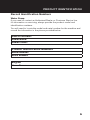
Record Identification Numbers
Water Pump
If you need to contact an Authorized Dealer or Customer Service line
for information on servicing, always provide the product model and
identification numbers.
You will need to locate the model and serial number for the machine and
record the information in the places provided below.
Date of Purchase:
Dealer Name:
Dealer Phone:
Product Identification Numbers
Model Number:
Serial Number:
Engine
Horse Power:
PRODUCT IDENTIFICATION

6
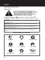
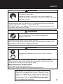
The safety alert symbol ( ) is used with a signal word (DANGER,
CAUTION, WARNING), a pictorial and/or a safety message to alert you
to hazards.
DANGER indicates a hazard which, if not avoided, will result in death
or serious injury.
WARNING indicates a hazard which, if not avoided, could result in
death or serious injury.
CAUTION indicates a hazard which, if not avoided, might result in
minor or moderate injury.
NOTICE indicates a situation that could result in equipment damage.
Follow safety messages to avoid or reduce the risk of injury or
death.
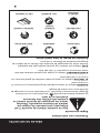
Hazard Symbols and Meanings
Save these Instructions
Safety Rules
This is the safety alert symbol. It is
used to alert you to potential personal
injury hazards. Obey all safety
messages that follow this symbol to
avoid possible injury or death.
explosion
kickback
moving parts read manual
hot surface
slippery
fire electric shock
toxic fumes
SAFETY

7
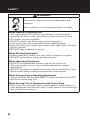
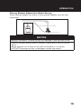
WARNING
Running engine gives off carbon monoxide, an odorless,
colorless, poison gas.
Breathing carbon monoxide can cause headache,
fatigue, dizziness, vomiting, confusion, seizures, nausea,
fainting or death.
• Operate water pump ONLY outdoors.
• Keep exhaust gas from entering a confined area through windows,
doors, ventilation intakes, or other openings.
• DO NOT start or run engine indoors or in an enclosed area, even if
windows and doors are open.
WARNING
Use of water pump can create puddles and
slippery surfaces.
• Operate water pump from a stable surface.
• The area should have adequate slopes and drainage to reduce the
possibility of a fall due to slippery surfaces.
WARNING
Unintentional sparking can result in fire or electric
shock.
When Adjusting or Making Repairs to Your Water Pump
• Disconnect the spark plug wire from the spark plug and place the
wire where it cannot contact spark plug.
When Testing for Engine Spark
• Use approved spark plug tester.
• DO NOT check for spark with spark plug removed.
SAFETY
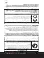
WARNING: This product can expose you to
chemicals including lead, which is known to the
State of California to cause cancer and birth
defects or other reproductive harm. For more
information, go to www.P65Warnings.ca.gov.
Wash hands after handling.

8
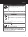
WARNING
Fuel and its vapors are extremely flammable and
explosive.
Fire or explosion can cause severe burns or death.
When Adding or Draining Fuel
• Turn water pump OFF and let it cool at least 2 minutes before
removing fuel cap. Loosen cap slowly to relieve pressure in tank.
• Fill or drain fuel tank outdoors.
• DO NOT overfill tank. Allow space for fuel expansion.
• If fuel spills, wait until it evaporates before starting engine.
• Keep fuel away from sparks, open flames, pilot lights, heat, and other
ignition sources.
• DO NOT light a cigarette or smoke.
When Starting Equipment
• Ensure spark plug, muffler, fuel cap, and air cleaner are in place.
• DO NOT crank engine with spark plug removed.
When Operating Equipment
• DO NOT pump flammable liquids, such as fuel or fuel oils.
• This water pump is not for use in mobile equipment or marine
applications.
• DO NOT tip engine or equipment at angle which causes fuel to spill.
• Secure water pump. Loads from hoses may cause tipover.
When Transporting or Repairing Equipment
• Transport/repair with fuel tank EMPTY or with fuel shutoff valve OFF.
• Disconnect spark plug wire.
When Storing Fuel or Equipment with Fuel in Tank
• Store away from furnaces, stoves, water heaters, clothes dryers, or
other appliances that have pilot light or other ignition source because
they can ignite fuel vapors.
SAFETY

9
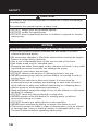
WARNING
Starter cord kickback (rapid retraction) can result in
bodily injury. Kickback will pull hand and arm toward
engine faster than you can let go.
Broken bones, fractures, bruises, or sprains could
result.
Keep hands and body clear from discharge of pump.
• When starting engine, pull cord slowly until resistance is felt and then
pull rapidly to avoid kickback.
• Secure discharge hose to avoid whipping.
WARNING
Contact with muffler area can result in serious burns.
Exhaust heat/gases can ignite combustibles, structures
or damage fuel tank causing a fire.
• DO NOT touch hot parts and AVOID hot exhaust gases.
• Allow equipment to cool before touching.
• Keep at least 5 feet (1.5 m) of clearance on all sides of pressure
washer including overhead.
WARNING
Starter and other rotating parts can entangle hands,
hair, clothing, or accessories.
• NEVER place hands or body parts inside of running pump or hoses.
• Never operate water pump without protective housing or covers.
• DO NOT wear loose clothing or anything that may be caught in the
starter or other rotating parts.
• Tie up long hair and remove jewelry.
SAFETY

10
CAUTION
Excessively high operating speeds increase risk of injury and damage
to water pump.
Excessively low speeds impose a heavy load.
• DO NOT tamper with the governed speed.
• DO NOT modify the water pump.
• DO NOT allow unqualified persons or children to operate or service
water pump.
NOTICE
Improper treatment of water pump can damage it and shorten its life.
• If you have questions about intended use, ask dealer or contact
nearest authorized dealer.
• Be sure pump chamber is filled with water before starting the engine.
Never run pump without priming.
• Use a non-collapseable hose on the suction side of the hose.
• Use water pump only for intended uses.
• Pumping sea water, beverages, acids, chemical solutions, or any other
liquid that promotes corrosion can damage the pump.
• Ensure all connections are air tight.
• DO NOT obstruct the suction or discharge hose in any way.
• NEVER operate pump without strainer basket connected to end of
suction hose.
• NEVER allow vehicles to drive over hoses. If a hose must be
positioned across a roadway, use planking on each side of hose to
allow vehicles to pass over without obstructing or collapsing hose.
• Anchor pump to avoid equipment movement.
• Keep equipment away from edge of river or lake where it could cause
the bank to collapse.
• DO NOT insert any objects through cooling slots.
• NEVER operate units with broken or missing parts, or without
protective housing or covers.
• DO NOT by-pass any safety device on this machine.
• NEVER move machine by pulling on hoses. Use frame on unit.
• Check fuel system for leaks or signs of deterioration, such as chafed
or spongy hose, loose or missing clamps, or damaged tank or cap.
Correct all defects before operating water pump.
SAFETY

11
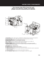
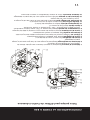
Your pump may differ from the unit
below. For specific model information,
please visit the manufacturers website.
1. Fuel Tank Fill tank with regular unleaded fuel. Always leave room for fuel expansion.
2. Priming Plug Fill pump with water here to prime pump before starting.
3. Discharge Outlet Connect discharge hose here.
4. Choke Lever Prepares a cold engine for starting.
5. Air Cleaner Protects engine by filtering dust and debris out of intake air.
6. Recoil Starter Used for starting the engine manually.
7. Engine Speed Lever Used to adjust engine speed to control pump output.
8. On/Off Switch Set this switch to “On” before using recoil starter. Set switch to
“Off” to stop a running engine.
9. Oil Drain Drain engine oil here.
10. Oil Fill Check and add engine oil here.
11. Suction Inlet Connect reinforced suction hose here.
12. Water Drain Plug Remove to drain water from pump and flush internal components
with clean water.
13. Pump Chamber Be sure to fill with water before starting.
14. Fuel Shutoff Valve Used to turn fuel supply on and off to engine.
1.
4.
6.
8.
9.
10.
11. 12. 13. 14.
7.
5.
2.
3.
WATER PUMP COMPONENTS

12
9
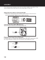
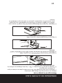
3. Slide hose clamp (A) over end of hose (B). Slide
suction hose onto hose barb (C). Tighten hose clamp
securely using a standard 1/4” (6mm) screwdriver.
Attach Suction Hose to Strainer Basket
Slide hose clamp over hose. Attach open end of suction hose
to strainer hose barb. Tighten hose clamp securely using a
standard 1/4” (6mm) screwdriver.
Connect Discharge Hose (Optional)
If desired, use a commercially available hose. DO NOT use a
hose with an inside diameter smaller than the pump’s
discharge port size.
1. Slide barb cuff over hose barb. Insert rubber seal into
end of barb cuff as shown earler.
2. Screw hose barb assembly onto pump in clockwise
rotation until hose barb assembly is tightened securely.
3. Slide hose clamp over end of discharge hose. Slide
discharge hose onto hose barb. Tighten hose clamp
securely using a standard 1/4” (6mm) screwdriver.
C
A
B
Your water pump requires some set up and is ready for use after it has
been properly serviced with the recommended oil and fuel.
Attach Suction Hose to Strainer Basket
1. Slide hose clamp over hose. Attach open end of suction hose to
strainer hose barb. Tighten hose clamp securely.
Connect Discharge Hose (Optional)
If desired, use a commercially available hose. DO NOT use a hose with
an inside diameter smaller than the pump’s discharge port size.
ASSEMBLY
Connect Suction Hose (Mandatory)
Attach Suction Hose by connecting camlocks.

13
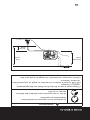
What is “Head”
Head refers to the height of a column of water that can be delivered by
the discharge of the pump.
Suction Head is the vertical distance between the center of the pump
and the surface of the liquid on the suction side of the pump. May also
be referred to as “suction lift”. The atmospheric pressure of 14.7 psi at
sea level limits suction head lift to less than approximately 26 feet for any
pump.
Discharge Head is the vertical distance between the pump’s discharge
port and the point of discharge, which is the liquid surface if the hose is
submerged or pumping into the bottom of a tank.
Total Head is the sum of the suction head value plus the discharge head
value.
As water pumping height increases, pump output decreases. The length,
type, and size of the suction and discharge hoses can also significantly
affect pump output.
It is important for the suction operation to be the shorter part of the total
pumping action. This will decrease the priming time and improve pump
performance by increasing the discharge head.
Suction head is a maximum of 25 feet and discharge head should be a
maximum of 81 feet. Total head can not be more than 106 feet as shown
on next page.
Move Water Pump to Safe Operating Location
For best pump performance, locate the pump on a flat, level surface as
close as possible to the water to be pumped. Secure water pump to
avoid tipover. Use hoses that are no longer than necessary.
IMPORTANT: Direct open end of discharge hose away from home,
electrical devices or anything not desired to get wet.
WARNING
Fuel and its vapors are extremely flammable and
explosive.
Fire or explosion can cause severe burns or death.
• This water pump is not for use in mobile equipment or marine
applications
• DO NOT tip engine or equipment at angle which causes fuel to spill.
• Secure water pump. Loads from hoses may cause tip over.
OPERATION

14
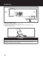
Discharge
Head
Total
Head
Suction
Head
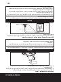
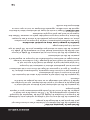
Prime the Water Pump
1. Remove priming plug from top of pump.
2. Fill pump with clean, clear water up to top of discharge outlet.
3. Replace priming plug.
NOTICE
Improper treatment of water pump can damage it and shorten its life.
• Be sure chamber is filled with water before starting the engine.
• NEVER run pump without priming
OPERATION

15
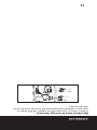
Placing Strainer Basket Into Water Source
Place strainer basket into water to be pumped. Basket must be fully
immersed.
NOTICE
Improper treatment of water pump can damage it and shorten its life.
• NEVER operate pump without strainer connected to end of suction
hose.
• Keep strainer out of sand or silt, place in bucket or on stones.
• DO NOT let pump run dry or damage to seals may result.
OPERATION

16
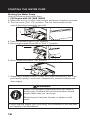
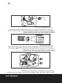
Starting the Water Pump
Use the following start instructions:
1. Fill Engine with Oil, SAE 10W30
2. Make sure unit is on a flat, level surface and pump chamber is primed.
3. Turn fuel valve (1) to “On” position. The fuel valve handle will be
vertical (pointing toward the ground).
4. Push on/off switch (2) to “On” position.
5. Move engine speed lever (3) to “Fast” ( ) position.
7. Grasp recoil handle and pull slowly until slight resistance is felt. Then
pull handle rapidly to overcome compression, prevent kickback and
start engine.
6. Move choke lever (4) to “On” position.
2
3
4
1
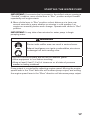
WARNING
Starter cord kickback (rapid retraction) can result in
bodily injury. Kickback will pull hand and arm toward
engine faster than you can let go.
Broken bones, fractures, bruises, or sprains could
result.
• When starting engine, pull cord slowly until resistance is felt and then
pull rapidly to avoid kickback.
STARTING THE WATER PUMP

17
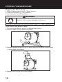
IMPORTANT: If excessive fuel is present in the air/fuel mixture causing a
“flooded” condition, move choke lever to “Run” position and pull handle
repeatedly until engine starts.
8. Move choke lever to “Run” position a short distance at a time over
several seconds in warm weather or minutes in cold weather. Let
engine run smoothly before each change. Operate with choke in “Run”
position.
IMPORTANT: It may take a few minutes for water pump to begin
pumping water.
WARNING
Contact with muffler area can result in serious burns.
Exhaust heat/gases can ignite combustibles, structures
or damage fuel tank causing a fire.
• DO NOT touch hot parts and AVOID hot exhaust gases.
• Allow equipment to cool before touching.
• Keep at least 5 feet (1.5 m) of clearance on all sides of pressure
washer including overhead.
Pump output is controlled by adjusting engine speed. Moving the engine
speed lever in the “Fast” direction will increase pump output, and moving
the engine speed lever in the “Slow” direction will decrease pump output.
STARTING THE WATER PUMP

18
WARNING
Backfire, fire or engine damage could occur.
• DO NOT stop engine by moving choke control to “Choke” position.
Stopping the Water Pump
1. Move engine speed lever to “Slow” position.
2. Push on/off switch to “Off” position.
3. Turn fuel valve to “Off” position.
Drain and Flush Water Pump
1. Disconnect and drain suction and discharge hoses.
2. Remove drain plug at bottom of pump.
3. Remove primer plug from top of pump and flush internal components
of pump with clean water.
4. Replace both plugs and finger tighten.
STOPPING THE WATER PUMP


La page est en cours de chargement...
La page est en cours de chargement...
La page est en cours de chargement...
La page est en cours de chargement...
La page est en cours de chargement...
La page est en cours de chargement...
La page est en cours de chargement...
La page est en cours de chargement...
La page est en cours de chargement...
La page est en cours de chargement...
La page est en cours de chargement...
La page est en cours de chargement...
La page est en cours de chargement...
La page est en cours de chargement...
La page est en cours de chargement...
La page est en cours de chargement...
La page est en cours de chargement...
La page est en cours de chargement...
La page est en cours de chargement...
La page est en cours de chargement...
-
 1
1
-
 2
2
-
 3
3
-
 4
4
-
 5
5
-
 6
6
-
 7
7
-
 8
8
-
 9
9
-
 10
10
-
 11
11
-
 12
12
-
 13
13
-
 14
14
-
 15
15
-
 16
16
-
 17
17
-
 18
18
-
 19
19
-
 20
20
-
 21
21
-
 22
22
-
 23
23
-
 24
24
-
 25
25
-
 26
26
-
 27
27
-
 28
28
-
 29
29
-
 30
30
-
 31
31
-
 32
32
-
 33
33
-
 34
34
-
 35
35
-
 36
36
-
 37
37
-
 38
38
-
 39
39
-
 40
40


Power Fist 8408890 Le manuel du propriétaire
- Taper
- Le manuel du propriétaire
- Ce manuel convient également à
dans d''autres langues
- English: Power Fist 8408890 Owner's manual
Documents connexes
Autres documents
-
Briggs & Stratton Plumbing Product 073004 WP15-225 Manuel utilisateur
-
-
-
Echo FP-2126 Manuel utilisateur
-
 BE Pressure Supply 8518250 Le manuel du propriétaire
-
red lion Engine-Driven Aluminum TRANSFER Pump Mode d'emploi
-
-
Simplicity 073022 Mode d'emploi
-
Wacker Neuson PG3A Manuel utilisateur
-
