Valor 1130FFK Le manuel du propriétaire
- Catégorie
- Cheminées
- Taper
- Le manuel du propriétaire

4004243-05
© Copyright Miles Industries Ltd., 2018.
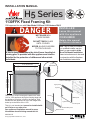
1130FFK Fixed Framing Kit
CSA approved for use with Valor Model 1100 and 1150 Heaters ONLY
Note: This kit must be installed
by a qualifi ed installer, service
agency or gas supplier at the
time of the heater installation.
These instructions are to be used
in conjunction with the fi replace
main installation instructions.
INSTALLER
Leave this manual
with the appliance.
CONSUMER
Retain this manual
for future reference.
The 1130FFK Fixed Framing Kit installs to the Valor
1100 or 1150 appliance during the framing stage and
the appliance’s position is fi xed in the framing. Wall
fi nishes are then applied over top of the fl anges and
butted up to the frame of the 1130.
This kit is not intended and
cannot be installed with
an H5 trim or any other trim
.
See appliance installation manual for more
information about fi nishing around this kit.
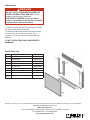
Overview
1100 or 1150 engine
Upper panel
LH panel
RH panel
Lower panel
RH door
LH door
Removable panel
Barrier screen
39-9/16” (1005 mm)
35-11/16” (906 mm)
32-5/8” (829 mm)
28-1/8” (714 mm)
1-1/8”
(29 mm)
HOT GLASS WILL
CAUSE BURNS.
DO NOT TOUCH GLASS
UNTIL COOLED.
NEVER ALLOW CHILDREN
TO TOUCH GLASS.
DANGER
!
A barrier designed to reduce the risk of burns from the hot
viewing glass is provided with this appliance and shall be
installed for the protection of children and other at-risk
individuals.
INSTALLATION MANUAL
H5 Series

2
Install Appliance with 1130 Fixed Framing Kit
The side brackets provided loose with the appliance
are not needed with this kit.
Hearth considerations
You need to know whether there will be a hearth or
not in front of the appliance and some rules must be
considered:
Without hearth
In the case where there is no hearth, the bottom of the
appliance must be raised at least 4” inches above any
combustible fl oor in front.
With hearth
Any hearth within 4” vertical of the base of the heater
must be non-combustible. See Hearth Requirements
section of the manual packed with the appliance.
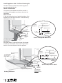
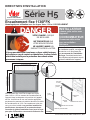
Section view, up the wall—detail
Section view, hearth—detail
Lower panel
Removable panel
1-1/8”
(29 mm)
Front of
appliance
Stud
Plywood base
Appliance base
Lower panel
Removable panel
Finishing up the wall
Stud
Plywood
base
Appliance base
Lower panel
Removable panel
Finishing with hearth
Non-combustible
material
1/2” insulating Micore panel
(supplied with appliance)
Plywood
sub-oor
1-1/2” (38 mm)
max. thickness
(including Micore)
Appliance base
1/2” combustible
shim at ends to
match Micore
Lower panel
Removable panel
1-1/2” (38 mm)
Front of
appliance
Plywood
Appliance base

3
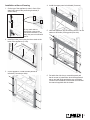
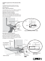
Installation at time of framing
1. On the top of the appliance’s case in front of the
stand-off s, remove the positioning brackets (2
screws each).
On top, each side of
the window, remove the
convection brackets (1 nut/
side); they are not used with
this kit.
2. Install the lower panel using the three studs at the
base of the appliance (3 nuts).
3. On the appliance, install the side panels as
indicated (3 screws per side).
4. Install the upper panel as indicated (2 screws).
5. Slide the appliance into the framing and fi x it to the
studs on each side (6 fi xing points per side).
6. Set aside the side doors, removable panel and
barrier screen to install later when the appliance’s
set-up and wall fi nish application are completed.
Continue the installation of the heater as indicated
the manual supplied with the heater.

4
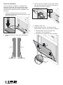
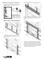
Finish kit installation
Once the appliance installation is completed with
gas supply connected, liners, fuel bed and window
installed, aeration checked, remote control paired
and wall fi nish completed, fi nish the installation of the
framing kit.
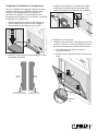
1. Slide the removable panel in the clip on the
horizontal supports on each side and push it in until
fl ush with the front trim.
2. Identify left hand door from right using diagram
below.
3. Position LH door to left side of front frame, identify
door slots top and bottom just behind front panel
and slide door locator in position.
4. Repeat for other door.
5. Install the barrier screen. The tabs rest at the
bottom and the screen is held in place by magnets.
a. Rest the bottom tabs on the edge of the
removable cover as indicated.
b. Push the screen against the steel front panel.
LH Door RH Door
nger grip inboard,
with locator on right
nger grip inboard,
with locator on left
a
a
b
tabs at the
bottom

5
WARNING
DO NOT TOUCH THE BARRIER SCREEN OR
DO NOT TOUCH THE BARRIER SCREEN OR
FIREPLACE WHILE THEY ARE HOT!
FIREPLACE WHILE THEY ARE HOT!
Let the
Let the
fi replace cool fi rst before cleaning it.
fi replace cool fi rst before cleaning it.
FOR SAFETY PURPOSE, ensure the barrier
FOR SAFETY PURPOSE, ensure the barrier
screen is re-installed on the fi replace front after
screen is re-installed on the fi replace front after
maintenance if it has been removed.
maintenance if it has been removed.
WARNING
!
Designed and Manufactured by / for
Miles Industries Ltd.
190 – 2255 Dollarton Highway, North Vancouver, BC, CANADA V7H 3B1
Tel. 604-984-3496 Fax 604-984-0246
www.valorfi replaces.com
Because our policy is one of constant development and improvement, details may vary slightly from those given in this publication.
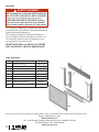
Code Description Part Number
1 RH side panel 4004377AZ
2 LH side panel 4004357AZ
3 Upper panel 4003765AZ
4 LH side door 4003881AZ
5 RH side door 4003882AZ
6 Lower panel 4004803AZ
7 Removable panel 4005824AZ
8 Barrier screen 4005632
not
shown
#8 x 1/2 s/t screws black (8)
Repair Parts List
Maintenance
To clean the frame, use mild soap and water. To clean
the screen, dust it with a soft brush.
To clean the window and ceramics inside the fi rebox,
consult the Owner’s Information section of the
Installation and Owner’s Manual supplied with the
fi replace.
DO NOT CLEAN THE GLASS WINDOW WITH
AMMONIA!
1
2
3
4
5
6
7
8

6
39-9/16” (1005 mm)
35-11/16” (906 mm)
32-5/8” (829 mm)
28-1/8” (714 mm)
Encadrement fi xe 1130FFK
Homologué pour utilisation avec les foyers Valor 1100 et 1150 SEULEMENT
L’Encadrement fi xe 1130FFK s’installe aux foyers
Valor 1100 ou 1150 au moment de l’encastrement de
l’appareil dans la charpente et la position de l’appareil
est fi xe. Les fi nitions du mur sont ensuite appliquées
par-dessus les panneaux de métal et aboutés à la saillie
de l’encadrement du 1130. Cet encadrement n’est pas
conçu pour être installé et ne peut être installé avec
des bordures, devantures H5 ou autres bordures.
Consultez le guide d’installation fourni avec le foyer
pour plus d’information concernant la fi nition du mur.
Concept
Foyer 1100 ou 1150
Panneau
du haut
Panneau
gauche
Panneau
droit
Porte
droite
Porte
gauche
Panneau amovible
Écran pare-étincelles
VITRE CHAUDE - RISQUE
DE BRÛLURES.
NE TOUCHEZ PAS UNE
VITRE NON REFROIDIE.
NE LAISSEZ JAMAIS UN
ENFANT TOUCHER LA VITRE.
L’écran pare-étincelles fourni avec ce foyer réduit le risque
de brûlure en cas de contact accidentel avec la vitre chaude
et doit être installé pour la protection des enfants et des
personnes à risques.
DANGER
!
INSTALLATEUR
Laissez cette notice avec
l’appareil.
CONSOMMATEUR
Conservez cette notice
pour consultation
ultérieure.
Note : Ce kit doit être installé par
un installateur qualifi é, une agence
de service ou un fournisseur de
gaz au moment de l’installation
du foyer. Ces directives doivent
être utilisées conjointement avec le
guide d’installation de l’appareil.
Panneau du bas
1-1/8”
(29 mm)
© Tous droits réservés, Miles Industries Ltd., 2018
Série H5
DIRECTIVES D’INSTALLATION
LE PREMIER
FOYER À GAZ RADIANT
MC
®

7
Installez l’appareil avec l’Encadrement fi xe
1130
Les supports des côtés de caisse fournis avec
l’appareil ne sont pas nécessaires pour installer
cet encadrement.
Dalle ou plancher protecteur
Vous devez savoir s’il y aura une dalle ou un plancher
protecteur devant le foyer ou non car certaines
exigences doivent être respectées.
Sans dalle ou plancher protecteur
Dans le cas ou il n’y a pas de dalle ou plancher
protecteur, le fond de l’appareil doit être surélevé d’au
moins 4 pouces (102 mm) lorsque le plancher devant
le foyer est combustible.
Avec dalle ou plancher protecteur
Toute dalle ou plancher protecteur à moins de 4
pouces (102 mm) de la base de l’appareil doit être
fabriqué de matériaux incombustible. Voir la section
Exigences pour dalle ou plancher protecteur au guide
d’installation fourni avec l’appareil.
Coupe transversale, au mur—detail
Poutre
Panneau du bas
Panneau amovible
Devant
du foyer
Contreplaqué
Base du foyer
1-1/8”
(29 mm)
Panneau
du bas
Panneau amovible
Finition au mur
Poutre
Feuille de
contreplaqué
Base du foyer
Coupe transversale,
dalle—detail
Panneau
du bas
Panneau amovible
Finition avec dalle
Matériau
incombustible
Panneau isolant Micore
de 1/2” (13 mm)
(fourni avec le foyer)
Sous-plancher
en contreplaqué
Épaisseur max.
de 1-1/2” (38 mm)
(incluant Micore)
Base du foyer
Cales combustibles de
1/2” (13 mm) d’épaisseur
à chaque bout du
panneau Micore pour
combler l’espace
Panneau du bas
Panneau amovible
1-1/2” (38 mm)
Devant
du foyer
Contreplaqué
Base du foyer

8
Installation au moment de l’encastrement
1. Sur le dessus de la caisse devant les écarteurs,
enlevez les angles de positionnement (2 vis
chacun).
En haut de l’appareil, de
chaque côté de la fenêtre,
enlevez les défl ecteurs de
convection (1 écrou/côté);ls
ne sont pas requis avec ce
kit.
2. Au bas de l’appareil, installez le panneau du bas
utilisant les écrous enlevés à l’étape précédente.
3. Sur l’appareil, de chaque côté de l’ouverture,
installez les panneaux des côtés tel qu’indiqué
(3 vis par côté).
4. Installez le panneau du haut tel qu’indiqué (2 vis).
5. Insérez l’appareil dans la charpente et fi xez-le aux
poutres de chaque côté (6 points de fi xation par
côté).
6. Mettez de côté les portes des côtés, le panneau
amovible et l’écran pare-étincelles pour installatio
plus tard lorsque l’installation des éléments internes
de l’appareil et la fi nition du mur seront complétés.
Continuez l’installation tel qu’indiqué dans le guide
d’installation fourni avec l’appareil.

9
Complétez l’installation de l’encadrement
Une fois l’installation de l’appareil complétée incluant
le branchement au gaz, l’installation des panneaux
intérieurs, du lit d’alimentation, de la fenêtre, la
vérifi cation de l’aération, la synchronisation de la
télécommande et la fi nition du mur terminés, complétez
l’installation de l’encadrement.
1. Placez le panneau amovible sur les supports au
bas de chaque côté et poussez-le en l’insérant
dans les attaches des supports pour le fi xer.
2. Identifi ez la porte gauche de la porte droite à l’aide
du schéma ci-dessous.
Porte
gauche
Porte
droite
crochets et onglet
s
positionnement à
d
crochets et onglets de
positionnement à gauche
3. Installez la porte gauche en insérant ses onglets
de positionnement dans les fentes situées juste
derrière le façade de l’encadrement tel qu’indiqué.
4. Répétez pour l’autre porte.
5. Installez le pare-étincelles. Les onglets du bas sont
posés sur le bord du couvercle amovible et le pare-
étincelles est maintenu en place par des aimants.
a. Posez les onglets du bas sur le bord du
couvercle amovible.
b. Poussez le pare-étincelles contre la bordure de
métal.
a
a
b
onglets du
bas

10
Conçue et fabriquée par / pour
Miles Industries Ltd.
190 – 2255 Dollarton Highway, North Vancouver, BC, CANADA V7H 3B1
Tél. 604-984-3496 Téléc. 604-984-0246
www.foyervalor.com
Parce que nous favorisons une politique de développement continu, certains détails de la présente publication peuvent varier.
Code Description Pièce n
o
1 Panneau côté droit 4004377AZ
2 Panneau côté gauche 4004357AZ
3 Panneau du haut 4003765AZ
4 Porte gauche 4003881AZ
5 Porte droite 4003882AZ
6 Panneau du bas 4004803AZ
7 Panneau amovible 4005824AZ
8 Écran pare-étincelles 4005632
pas
montrées
Vis noires #8 x 1/2 s/t (8)
Liste de pièces
Entretien
Pour nettoyer l’encadrement, utilisez une solution d’eau
et de savon doux. Époussettez l’écran pare-étincelles à
l’aide d’une brosse à poils doux.
Pour nettoyer la fenêtre et l’intérieur de la boîte de
foyer, consultez la section Information à l’intention du
consommateur dans le Guide de l’installation et du
consommateur fourni avec le foyer.
NE NETTOYEZ PAS LA VITRE DE LA FENÊTRE
AVEC UN PRODUIT À BASE D’AMMONIAQUE!
AVERTISSEMENT
NE TOUCHEZ PAS L’ÉCRAN PARE-ÉTINCELLES
NE TOUCHEZ PAS L’ÉCRAN PARE-ÉTINCELLES
OU LE FOYER LORSQU’ILS SONT CHAUDS!
OU LE FOYER LORSQU’ILS SONT CHAUDS!
Laissez le foyer refroidir avant de le nettoyer.
Laissez le foyer refroidir avant de le nettoyer.
POUR DES RAISONS DE SÉCURITÉ, assurez-
POUR DES RAISONS DE SÉCURITÉ, assurez-
vous que l’écran pare-étincelles est réinstallé
vous que l’écran pare-étincelles est réinstallé
sur la bordure après l’entretien s’il a été enlevé.
sur la bordure après l’entretien s’il a été enlevé.
AVERTISSEMENT
!
1
2
3
4
5
6
7
8
-
 1
1
-
 2
2
-
 3
3
-
 4
4
-
 5
5
-
 6
6
-
 7
7
-
 8
8
-
 9
9
-
 10
10


Valor 1130FFK Le manuel du propriétaire
- Catégorie
- Cheminées
- Taper
- Le manuel du propriétaire
dans d''autres langues
- English: Valor 1130FFK Owner's manual
Documents connexes
-
Valor 1140FS Le manuel du propriétaire
-
-
-
-
-
-
-
-
-