
REV 001
b
High
Quality
Nautical
Equipment
Manuale d'uso SALPA ANCORA VERTICALI
User's Manual VERTICAL WINDLASSES
Manuel de l'utilisateur GUINDEAUX VERTICAUX
Benutzerhandbuch VERTIKAL ANKERWINDEN
Manual del usuario MOLINETES VERTICALES
DP1 SERIE PRINCE
300/500W
DP1 312
DP1 512
DP1 524
IT
GB
FR
DE
ES


3
DP1 300/500W - REV001B
Pag. 4 Caratteristiche tecniche
Pag. 5 Installazione
Pag. 6 Schema di collegamento
Pag. 7 Uso - Avvertenze importanti
Pag. 8/9 Manutenzione
Pag. 10/11 Set
Pag. 12 Technical data
Pag. 13 Installation
Pag. 14 Connection diagram
Pag. 15 Usage - Warning
Pag. 16/17 Maintenance
Pag. 18/19 Set
Pag. 20 Caractéristiques techniques
Pag. 21 Installation
Pag. 22 Schéma de cablage
Pag. 23 Utilisation - Avvertissements importants
Pag. 24/25 Entretien
Pag. 26/27 Groupe
Seite 28 Technische Eigenschaften
Seite 29 Montage
Seite 30 Anschlussplan
Seite 31 Gebrauch - Wichtige Hinweise
Seite 32/33 Wartung
Seite 34/35 Gruppe
Pág. 36 Características técnicas
Pág. 37 Instalación
Pág. 38 Esquema de montage
Pág. 39 Uso - Advertencias importantes
Pág. 40/41 Mantenimiento
Pág. 42/43 Grupo
INDICE
INDEX
SOMMAIRE
INHALTSANGABE
INDICE
IT
GB
FR
DE
ES

4
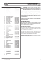
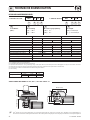
CARATTERISTICHE TECNICHE
IT
DP1 300/500W - REV001B
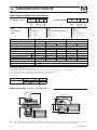
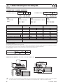
1° ESEMPIO: DP1312D
DP1 3 12 D
a
DP1 5 24
-
Nome della serie:
[ DP1 ]
Potenza motore:
[ 3 ]
= 300 W
[ 5 ]
= 500 W
Tensione alimentazione motore:
[ 12 ]
= 12 V
[ 24 ]
= 24 V
Campana:
[ D ]
= con campana
[ - ]
= senza campana
(1) Dopo un primo periodo d’uso.
(2) Misure effettuate con barbotin per catena da 8 mm.
(3) Valore minimo consigliato per una lunghezza totale L<20m (Vedi pag. 44). Calcolare la sezione in funzione della lunghezza del collegamento.
(4) Con interruttore specifico per correnti continue (DC) e ritardato (magneto-termico o magneto-idraulico).
(5) Su richiesta possono essere forniti alberi e prigionieri per spessori di coperta maggiori.
(6) Solo su richiesta.
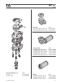
COME SI LEGGE IL MODELLO DEL SALPA ANCORA:
A B C D
A B C D A B C D
2° ESEMPIO: DP1524
a
a
a
a
a
a
a
85 (3
7
/32)
271 (9
5
/8)
61 (2
13
/
32
) 69 (2
23
/
32
)
181 (7
23
/32)
122 (4
11
/16)
134,4 (5
9
/32)
75,4 (2
31
/32)
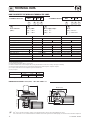
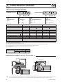
DIMENSIONI DEI MODELLI mm ( inch ) • DP1 300 / 500W - / D
(*) Per i codici dei barbotin fare riferimento all’esploso a pag 8.
Quick
®
si riserva il diritto di apportare modifiche alle caratteristiche tecniche dell'apparecchio e al contenuto di questo manuale senza alcun preavviso.
In caso di discordanze o eventuali errori tra il testo tradotto e quello originario in italiano, fare riferimento al testo italiano o inglese.
F
BARBOTIN (*)
6 mm 1/4”
Catena supportata
6 mm 6 mm 1/4”
DIN 766 ISO BBB
MODELLI
DP1 – / D DP1 HI SPEED
(6)
POTENZA MOTORE
300W 500W 500W
Tensione motore 12V 12V 24V 12V 24V
Tiro istantaneo massimo 370 kg (815,7 lb) 660 kg (1455,0 lb) 600 kg (1322,8 lb)
Carico di lavoro massimo 120 kg (264,5 lb) 200 kg (440,9 lb) 220 kg (485,0 lb) 170 kg (374,8 lb) 200 kg (440,9 lb)
Carico di lavoro 40 kg (88,2 lb) 65 kg (143,3 lb) 70 kg (154,3 lb) 65 kg (143,3 lb) 70 kg (154,3 lb)
Assorbimento corrente al carico di lavoro (1) 65 A 80 A 40 A 100 A 50 A
Velocità massima di recupero (2)
m/min
26,3 (86,3 ft/min) 28,9 (94,8 ft/min) 28,2 (92,5 ft/min) 43,0 (141,1 ft/min) 42,5 (139,4 ft/min)
Velocità di recupero al carico di lavoro (2)
m/min
24,4 (80,1 ft/min) 24,3 (79,7 ft/min) 24,1 (79,1 ft/min) 34,5 (113,2 ft/min) 35,0 (114,8 ft/min)
Sezione minima cavi motore (3) 16 mm
2
(AWG5) 10 mm
2
(AWG7) 25 mm
2
(AWG3) 10 mm
2
(AWG7)
Interruttore di protezione (4) 50 A 60 A 40 A 80 A 40 A
Spessore coperta (5) 20 ÷ 30 mm (25/32” ÷ 1” 3/16)
Peso - modello senza campana 7,6 Kg (16,7 lb)
Peso - modello con campana 8,4 Kg (18,5 lb)

5
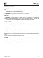
INSTALLAZIONE
IT
DP1 300/500W - REV001B
ATTENZIONE:
prima di effettuare il collegamento accertarsi che non sia presente l'alimentazione su cavi.
PRIMA DI UTILIZZARE IL SALPA ANCORA LEGGERE ATTENTAMENTE IL PRESENTE MANUALE D'USO.
IN CASO DI DUBBI CONSULTARE IL RIVENDITORE QUICK
®
.
ATTENZIONE:
i salpa ancora Quick
®
sono stati progettati e realizzati per salpare l'ancora. Non utilizzare questi apparecchi
per altri tipi di operazioni.
Quick
®
non si assume alcuna responsabilità per i danni diretti o indiretti causati da un uso impro-
prio dell'apparecchio. Il salpa ancora non è progettato per sostenere carichi generati in particolari condizioni atmosferiche
(burrasca).
Disattivare sempre il salpa ancora quando non è in uso. Accertarsi che non vi siano bagnanti nelle vicinanze
prima di calare l’ancora.
La giunzione tra la cima e la catena deve avere dimensioni ridotte per poter scorrere agevolmente
dentro la sagoma del barbotin. Per qualsiasi problema o richiesta contattare l’assistenza Quick
®
. Per maggiore sicurezza, nel
caso in cui uno si danneggi suggeriamo di installare almeno due comandi per l’azionamento del salpa ancora.
Consigliamo l’uso dell’interruttore magneto-idraulico Quick
®
come sicurezza per il motore. Bloccare la catena con un
fermo prima di partire per la navigazione.
La scatola teleruttori o teleinvertitori deve essere installata in un luogo protetto da
possibili entrate d’acqua.
Dopo aver completato l’ancoraggio, fissare la catena o cima a punti fissi quali chian stopper o bitta.
Per prevenire rilasci non voluti l’ancora deve essere fissata, il salpa ancora non deve essere usato come unica presa di forza.
Isolare il salpa ancora dall’impianto elettrico durante la navigazione (disinserire l’interruttore di protezione del motore) e bloc-
care la catena ad un punto fisso dell’imbarcazione.
LA CONFEZIONE CONTIENE:
salpa ancora (top + motoriduttore) - cassetta teleinvertitori - guarnizione della base - dima di foratura
- leva - viterie (per l'assemblaggio) - manuale di istruzioni - condizioni di garanzia.
ATTREZZI NECESSARI PER L'INSTALLAZIONE:
trapano con punte: Ø 9 mm (23/64") e Ø 11 mm (7/16”); a tazza Ø 46 mm (1"13/16) e
Ø 62 mm (2"7/16); chiave esagonale: 13 mm.
ACCESSORI QUICK
®
CONSIGLIATI:
deviatore da pannello (mod. 800) - Pulsantiera stagna (mod. HRC 1002) - Pulsante a piede (mod.
900) - Interruttore magneto-idraulico - Conta catena per l'ancoraggio (mod. CHC 1102M e CHC 1202M) - Sistema di comando via radio
RRC (mod. R02, PO2, H02).
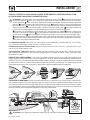
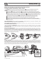
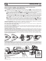
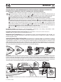
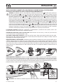
REQUISITI PER L'INSTALLAZIONE:
il salpa ancora va posizionato allineando il barbotin con il puntale di prua. Verificare che le
superfici superiore e inferiore della coperta siano più parallele possibili; se ciò non dovesse accadere compensare opportunamente la
differenza (la mancanza di parallelismo potrebbe causare perdite di potenza del motore). Lo spessore di coperta dovrà essere compreso
fra i valori indicati in tabella. Se si avessero spessori differenti è necessario consultare il rivenditore Quick
®
. Non devono esistere ostacoli
sotto coperta per il passaggio di cavi, cima e catena, la poca profondità del gavone potrebbe provocare inceppamenti.
PROCEDURA DI MONTAGGIO:
stabilita la posizione ideale praticare i fori utilizzando la dima di foratura fornita a corredo. Rimuo-
vere il materiale in eccesso dal foro di passaggio della catena/cima, rifinirlo e lisciarlo con un prodotto specifico (vernice marittima, gel o
resina epossidica) assicurando il libero passaggio della catena/cima. Posizionare la parte superiore, inserendo la guarnizione fra la coper
-
ta e la base e collegare a questa la parte inferiore, infilando l'albero nel riduttore. Fissare il salpa ancora avvitando i dadi sui prigionieri di
bloccaggio. Collegare i cavi di alimentazione provenienti dal salpa ancora al teleinvertitore.
Max
5 mm
(3/16”)
40 cm (16”)
P
A
I
N
T
45°
Possibili installazioni
dei motoriduttori

6
IT
DP1 300/500W - REV001B
-
+
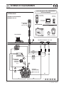
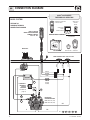
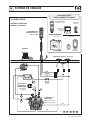
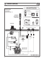
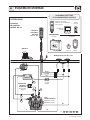
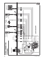
SISTEMA BASE
SCHEMA DI COLLEGAMENTO
GENERALE PAG. 44
PULSANTIERA
MULTIUSO
MOD. HRC 1002
SALPA ANCORA
MOTORE
BATTERIA
INTERRUTTORE
MAGNETO
IDRAULICO
(vedi tabella
pag. 4)
CASSETTA
TELEINVERTITORI
MOD. T6415-12 (12V)
MOD. T6415-24 (24V)
C A2
PULSANTI A PIEDE
MOD. 900U E 900D
NERO
MARRONE
BLU
A1
FUSIBILE
4A (12V)
2A (24V)
L = L1 + L2 + L3 + L4 + L5
MARRONE
NERO
BLU
L1
L2 L3
L4
L5
SCHEMA DI COLLEGAMENTO
CONTACATENA
DA PANNELLO
COMANDO
DA PLANCIA
PULSANTIERA
CONTACATENA
TASCABILE - PULSANTIERA
RICEVITORE
ACCESSORI QUICK
®
PER L'AZIONAMENTO
DEL SALPA ANCORA
TRASMETTITORI
RADIOCOMANDI

7
IT
DP1 300/500W - REV001B
AVVERTENZE IMPORTANTI
ATTENZIONE:
non avvicinare parti del corpo o oggetti alla zona in cui scorrono catena, cima e barbotin. Accertarsi
che non sia presente l’alimentazione al motore elettrico quando si opera manualmente sul salpa ancora (anche quando
si utilizza la leva per allentare la frizione); infatti persone dotate di comando a distanza del salpa ancora (pulsantiera
remota o radiocomando) potrebbero accidentalmente attivarlo.
ATTENZIONE:
bloccare la catena con un fermo prima di partire per la navigazione.
ATTENZIONE:
non attivare elettricamente il salpa ancora con la leva inserita nella campana o nel coperchio del
barbotin.
ATTENZIONE:
Quick
®
consiglia di utilizzare un interruttore specifico per correnti continue (DC) e ritardato (magneto
termico o magneto idraulico) per proteggere la linea del motore da surriscaldamenti o corto-circuiti. L’interruttore può
essere utilizzato per isolare il circuito di comando del salpa ancora evitando così azionamenti accidentali.
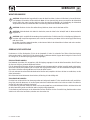
USO DELLA FRIZIONE
Il barbotin è reso solidale all’albero principale (11 o 12) dalla frizione (5). La frizione si apre (stacco) utilizzando la leva (1) che
inserita nella bussola (2) della campana o nel coperchio barbotin (4) dovrà ruotare in senso antiorario. Ruotando in senso orario
si provocherà la chiusura (attacco) della frizione.
PER SALPARE
Accendere il motore dell’imbarcazione. Assicurarsi che la frizione sia serrata ed estrarre la leva.
Premere il pulsante UP del comando a vostra disposizione.
Se il salpa ancora si arresta senza che l’interruttore magneto-idraulico (o magnetotermico) sia scattato, attendere qualche
secondo e riprovare (evitare una pressione continuata del pulsante).
Se l’interruttore magneto-idraulico (o magnetotermico) è scattato, riattivare l’interruttore e attendere qualche minuto prima di
riprendere a salpare.
Se, dopo ripetuti tentativi, il salpa ancora continua a bloccarsi consigliamo di manovrare l’imbarcazione per disincagliare
l’ancora.
Controllare la salita degli ultimi metri di catena per evitare danni alla prua.
PER CALARE
La calata dell’ancora si può effettuare tramite comandi elettrici oppure manualmente. Per effettuare l’operazione manualmente
occorre aprire la frizione lasciando libero il barbotin di girare sul proprio asse e trascinare la catena o la cima in acqua.
Per frenare la caduta dell’ancora bisogna ruotare la leva in senso orario.
Per calare l’ancora elettricamente occorre premere il pulsante DOWN del comando a vostra disposizione. In questo modo la
calata è perfettamente controllabile e lo svolgimento della catena o della cima è regolare.
Per evitare sollecitazioni sul salpa ancora, una volta ancorati, bloccare la catena con un fermo oppure fissarla ad un punto
saldo con una cima.
USO

8
IT
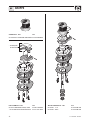
DP1 300/500W - REV001B
43
42
44
41
45
40
39
38
36
34
35
31
30
32
1
2
3
4
6
21
22
7
15
8
9
10
11
13
14
14
14
12
9
5
5
33
37
16
24
25
27
29
28
20
17
18
23
26
19
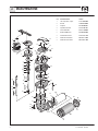
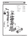
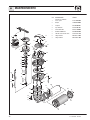
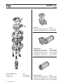
POS.
DENOMINAZIONE CODICE
1 Leva salpa dritta - nylon PVLVSDN00000
2 Bussola SGMSD0400000
3 Campana MSE050000R03
4 Coperchio barbotin ZSPMSGB05R03
5 Cono frizione DP1 MSFDP1000000
6 Barbotin 500W 6mm MSB040600000
7 Paraolio 20*42*7mm PGPRL2042700
8 Anello elastico interno MBAN4217Y000
9 Anello elastico esterno MBAE2012Y000
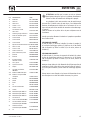
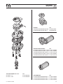
MANUTENZIONE

9
IT
DP1 300/500W - REV001B
ATTENZIONE:
accertarsi che non sia presente l’alimenta-
zione al motore elettrico quando si opera manualmente sul
salpa ancora; rimuovere con cura la catena dal barbotin o la
cima dalla campana.
I salpa ancora Quick
®
sono costituiti da materiali resistenti all’am-
biente marino: è indispensabile, in ogni caso, rimuovere periodica-
mente i depositi di sale che si formano sulle superfici esterne per
evitare corrosioni e di conseguenza danni all’apparecchio.
Lavare accuratamente con acqua dolce le superfici e le parti in cui
il sale può depositarsi.
Smontare una volta all’anno il barbotin e la campana attenendosi
alla seguente sequenza:
VERSIONE CON CAMPANA
Con la leva (1) svitare la bussola (2); estrarre la campana (3) e il cono
frizione superiore (5); svitare le viti di fissaggio (20) dello stacca cate-
na (21) e rimuoverlo; estrarre il barbotin (6).
VERSIONE SENZA CAMPANA
Con la leva (1) svitare il coperchio barbotin (4); estrarre il cono frizio-
ne superiore (5); svitare le viti di fissaggio (20) dello stacca catena
(21) e rimuoverlo; estrarre il barbotin (6).
Pulire ogni parte smontata affinché non si verifichino attacchi di
corrosione e ingrassare (con grasso marino) il filetto dell’albero (11
o 12) e il barbotin (6) dove appoggiano i coni frizione (5).
Rimuovere eventuali depositi di ossido sui morsetti della cassetta
teleinvertitori; cospargerli di grasso.
POS. DENOMINAZIONE CODICE
10 Cuscinetto MBJ160040000
11 Albero DP1 MSASDP100R00
12 Albero DP1 D MSASDP1D0R00
13 Chiavetta 6*6*25 MBH060625X00
14 Chiavetta 6*6*50 MBH060650X00
15 Paraolio 20*35*7mm PGPRL2035700
16 Coperchio guida catena DP1 -
17 Passacatena DP1 plastica PDPSSDP10R01
18 Vite M 4*30 inox MBV0430MXVEP
19 Vite M 5*30 inox MBV0530MXCE0
20 Vite M 5*40 inox MBV0540MXCE0
21 Stacca catena DP1 inox SPMSNDP10000
22 Spina 4*22 inox MBSC04022A00
23 Vite M 6*12 inox MBV0612MXTSC
24 Cover base DP1 inox SPMSGB0DP1X0
25 Inserto cover DP1 plastica PDNC0DP10000
26 Dado M4 MBD04MXEN000
27 Dado M5 MBD05MXEN000
28 Base circolare DP1
alluminio anodizzato
SGMSC0DP1A00
29 Guarnizione PGBSDP100000
30 Sensore KNREEDCL0000
31 Prigioniero MBP080608X00
32 Guarnizione flangia riduttore
300/500W
PGFLRDTG4000
33A Riduttore 500W serie Quick SLMR05TG4000
33B Riduttore Hi Speed 500W
serie Quick SLMR05TG40HS
34 Rondella MBR08X000000
35 Rondella dentellata MBR08XDE0000
36 Dado MBD08MXEN000
37 Vite MBV0516MXE00
38 Guarnizione motoriduttore PGBMR0400000
39 Chiavetta MBH040415F00
40A Motore 300W 12V EMF031200000
40B Motore 500W 12V EMF051200000
40C Motore 500W 24V EMF052400000
41 Guarnizione flangia PGGPMFN04000
42 Carter 300/500W PCCCPM040000
43
Guarnizione poli
motore 300/500W
PGGPMPM04000
44 Coperchio fondo
motore 300/500W
PCCPPMFN0400
45 Vite MBV03916AXCC
MANUTENZIONE

10
IT
DP1 300/500W - REV001B
SET
CAMPANA - DP1
CODICE
OSP CAMPANA SALPA 500W Ø50MM FVSSMSE04000A00
BASE COMPLETA - DP1
CODICE
OSP BASE SALPA SERIE DP1 COMP FVSSBDP110C00A00
* OSP KIT COPERCHIO GUIDA CATENA DP1 FVSSCPSCDP10A00
TOP CON CAMPANA - DP1
CODICE
OSP TOP DP1 1/4” D FVSSTDP1D001A00
OSP TOP DP1 6MM D FVSSTDP1D006A00
* KIT COPERCHIO
GUIDA CATENA

11
IT
DP1 300/500W - REV001B
SET
RIDUTTORE
CODICE
OSP RIDUTTORE 500W SALPA QUICK TG40 FVSSMR05TG40A00
OSP RIDUTTORE 500W SALPA QUICK TG40 HS FVSSMR0540HSA00
MOTORIDUTTORE
CODICE
OSP MOTORIDUTTORE 300W 12V QUICK FVSSR0312Q00A00
OSP MOTORIDUTTORE 500W 12V QUICK FVSSR0512Q00A00
OSP MOTORIDUTTORE 500W 12V QUICK HS FVSSR0512QHSA00
OSP MOTORIDUTTORE 500W 24V QUICK FVSSR0524Q00A00
OSP MOTORIDUTTORE 500W 24V QUICK HS FVSSR0524QHSA00
MOTORE
CODICE
OSP MOTORE SALPANCORA 300W 12V FVSSM0312000A00
OSP MOTORE SALPANCORA 500W 12V FVSSM0512000A00
OSP MOTORE SALPANCORA 500W 24V FVSSM0524000A00
TOP SENZA CAMPANA - DP1
CODICE
OSP TOP DP1 1/4” FVSSTDP10001A00
OSP TOP DP1 6MM FVSSTDP10006A00

12
TECHNICAL DATA
GB
DP1 300/500W - REV001B
Quick
®
reserves the right to introduce changes to the equipment and the contents of this manual without prior notice.
In case of discordance or errors in translation between the translated version and the original text in the Italian language, reference will be made to the Italian or English text.
F
1° EXAMPLE: DP1312D
DP1 3 12 D
a
DP1 5 24
-
Name of the line:
[ DP1 ]
Motor power:
[ 3 ]
= 300 W
[ 5 ]
= 500 W
Motor supply voltage:
[ 12 ]
= 12 V
[ 24 ]
= 24 V
Drum:
[ D ]
= with drum
[ - ]
= without drum
(1) After an initial period of use.
(2) Measurements taken with a gypsy for a 8 mm chain.
(3) Minimum allowable value for a total length L<20m (see pag. 44). Determine the cable size according to the length of the wiring.
(4) With circuit breaker designed for direct currents (DC) and delayed-action (thermal-magnetic or hydraulic-magnetic).
(5) On request, shafts and studs can be supplied for greater deck thicknesses.
(6) Only on request.
HOW TO IDENTIFY THE WINDLASS THROUGH THE CODE:
A B C D
A B C D A B C D
2° EXAMPLE: DP1524
a
a
a
a
a
a
a
85 (3
7
/32)
271 (9
5
/8)
61 (2
13
/
32
) 69 (2
23
/
32
)
181 (7
23
/32)
122 (4
11
/16)
134,4 (5
9
/32)
75,4 (2
31
/32)
DIMENSIONS OF MODELS mm ( inch ) • DP1 300 / 500W - / D
(*) For the gypsy codes, please consult the exploded drawing on page 16.
MODELS
DP1 – / D DP1 HI SPEED
(6)
MOTOR POWER
300W 500W 500W
Motor supply voltage 12V 12V 24V 12V 24V
Maximum pull 370 kg (815,7 lb) 660 kg (1455,0 lb) 600 kg (1322,8 lb)
Maximum working load 120 kg (264,5 lb) 200 kg (440,9 lb) 220 kg (485,0 lb) 170 kg (374,8 lb) 200 kg (440,9 lb)
Working load 40 kg (88,2 lb) 65 kg (143,3 lb) 70 kg (154,3 lb) 65 kg (143,3 lb) 70 kg (154,3 lb)
Current absorption @ working load (1) 65 A 80 A 40 A 100 A 50 A
Maximum chain speed (2)
m/min
26,3 (86,3 ft/min) 28,9 (94,8 ft/min) 28,2 (92,5 ft/min) 43,0 (141,1 ft/min) 42,5 (139,4 ft/min)
Max. chain speed @ working load (2)
m/min
24,4 (80,1 ft/min) 24,3 (79,7 ft/min) 24,1 (79,1 ft/min) 34,5 (113,2 ft/min) 35,0 (114,8 ft/min)
Motor cable size (3) 16 mm
2
(AWG5) 10 mm
2
(AWG7) 25 mm
2
(AWG3) 10 mm
2
(AWG7)
Protection circuit breaker (4) 50 A 60 A 40 A 80 A 40 A
Deck thickness (5) 20 ÷ 30 mm (25/32” ÷ 1” 3/16)
Weight - model without drum 7,6 Kg (16,7 lb)
Weight - model with drum 8,4 Kg (18,5 lb)
GYPSY (*)
6 mm 1/4”
Chain size
6 mm 6 mm 1/4”
DIN 766 ISO BBB

13
INSTALLATION
GB
DP1 300/500W - REV001B
WARNING:
before wiring up, be sure the electrical cables are not live.
BEFORE USING THE WINDLASS READ THESE INSTRUCTIONS CAREFULLY.
IF IN DOUBT, CONTACT YOUR NEAREST “QUICK
®
” DEALER.
WARNING:
the Quick
®
windlasses are designed to weigh the anchor. Do not use the equipment for other purposes.
Quick
®
shall not be held responsible for damage to equipment and/or personal injury, caused by a faulty use
of the equipment.
The windlass is not designed for the loads that might occur in extreme weather conditions (storms).
Always deactivate the windlass when not in use. Check that there are no swimmers nearby before dropping anchor.
The splice between the rope and the chain must be tightly woven for the rope to slide easily into the gypsy shape. For
any problem or request, feel free to contact Quick
®
Technical Service. For improved safety we recommend installing at
least two anchor windlass controls in case one is accidentally damaged.
We recommend the use of the Quick
®
hydraulic-
magnetic switch as the motor safety switch.
Secure the chain with a further device before starting the navigation.
The contactor unit or reversing contactor unit must be installed in a point protected from accidental water contact.
After completing the anchorage, secure the chain or rope to fixed points such as chain stopper or bollard.
To prevent accidental releases, the anchor must be secured. The windlass shall not be used as the only securing device.
Isolate the windlass from the power system during navigation (switch the circuit breaker off) and lock the chain securing it to
a fixed point of the boat.
THE PACKAGE CONTAINS:
windlass (on deck unit + motorgearbox) - reversing contactor unit - base gasket - drill template - handle
- bolts and screws (for assembly) - user’s manual - conditions of warranty.
TOOLS REQUIRED FOR INSTALLATION:
drill and drill bits: 9 mm (23/64") and Ø 11 mm (7/16”); Ø 46 mm (1"13/16) and Ø 62 mm
(2"7/16) hollow mill; hexagonal wrench: 13 mm.
“QUICK
®
”ACCESSORIES RECOMMENDED:
anchoring RL control board (mod. 800) - Waterproof hand helds R/C (mod. HRC1002)
- Foot switch (mod. 900) - Hydraulic-magnetic circuit breaker - Anchor chain counter (mod. CHC1102M and CHC1202M) - Radio control
RRC (mod. R02, PO2, H02).
INSTALLATION REQUIREMENTS:
the windlass must be positioned with the gypsy aligned with the bow roller. Ensure that the up-
per and lower surfaces of the deck are as parallel as possible. If this is not the case, compensate the difference appropriately (a lack of
parallelism could result in a loss of motor power). The deck thickness must be included among the figures listed in the table. In cases of
other thicknesses it is necessary to consult a Quick
®
retailer. There must be no obstacles under deck to the passage of cables, rope and
chain; lack of depth of the peak could cause jamming.
FITTING PROCEDURE:
when the ideal position has been established, drill four holes using the drilling template provided.Remove
excess material from the chain passage, refine and flatten with a specialized product (marine paint, gel coat or two pack epoxy) to
assure free passage for both rope and chain. Position the upper section, inserting the gasket between the deck and the base and
connect the lower section to the assembly, inserting the shaft into the reduction unit. Fix the windlass by screwing the nuts onto the
fixing studs. Connect the supply cables from the windlass to the reversing contactor unit.
Max
5 mm
(3/16”)
40 cm (16”)
P
A
I
N
T
45°
Available motorgear-
boxes positioning

14
GB
DP1 300/500W - REV001B
-
+
BASIC SYSTEM
SEE PAGE 44
SHOWING THE MAIN
CONNECTION DIAGRAM
MULTI-PURPOSE
WATERTIGHT HAND HELD
REMOTE CONTROL
MOD. HRC 1002
WINDLASS
MOTOR
BATTERY
HYDRAULIC-
MAGNETIC
CIRCUIT
BREAKER
(see table on
page 12)
REVERSING
CONTACTOR UNIT
MOD. T6415-12 (12V)
MOD. T6415-24 (24V)
C
A2
FOOT SWITCHES
MOD. 900U AND 900D
BLACK
BROWN
BLUE
A1
FUSE
4A (12V)
2A (24V)
BROWN
BLACK
BLUE
L = L1 + L2 + L3 + L4 + L5
L1
L2 L3
L4
L5
CONNECTION DIAGRAM
RADIO POCKET
WATERTIGHT
PANEL
CHAIN COUNTER
WINDLASSES
CONTROL
BOARD
WATERTIGHT HAND HELD
CHAIN COUNTER
HANDHELD
RECEIVER
QUICK
®
ACCESSORIES
FOR WINDLASS OPERATION
TRANSMITTERS
REMOTE RADIO CONTROLS
RADIO POCKET

15
GB
DP1 300/500W - REV001B
WARNING
WARNING:
stay clear of the chains, ropes and gypsy. Make sure the electric motor is off when windlass is used manu-
ally (even when using the handle to disengage the clutch). In fact people with windlass remote controls (hand-held re-
mote control or radio-controlled systems) might accidentally operate it.
WARNING
: secure the chain with a device before starting the navigation.
WARNING
: do not operate the windlass by using the electrical power when the handle is inserted in the drum or into
the gypsy cover.
WARNING
: Quick
®
recommend using a circuit breaker designed for direct current (DC) with delayed-action (thermal-
magnetic or hydraulic-magnetic) to protect the motor supply line from overheating or short circuits. The circuit breaker
can be used to cut off power to the windlass control circuit and so avoid accidental activation.
CLUTCH USE
The clutch (5) provides a link between the gypsy and the main shaft (11 or 12). The clutch can be released (disengagement)
by using the handle (1) which, when inserted in the bush (2) of the drum or into the gypsy cover (4), must be turned counter-
clockwise. The clutch will be re-engaged by turning it clockwise (engagement).
WEIGHING THE ANCHOR
Turn on the engine. Make sure the clutch is engaged and remove the handle. Press the UP button on the control provided.
If the windlass stops and the hydraulic magnetic switch (or thermal cutout) has not tripped, wait a few seconds and try again
(avoid keeping the button pressed).
If the hydraulic magnetic switch, has tripped, reset it and wait a few minutes before weighing anchor once again.
If, after a number of attempts, the windlass is still blocked, we suggest to move the boat to release the anchor. Check the up-
ward movement of the chain for the last few meters in order to avoid damages to the bow.
CASTING THE ANCHOR
The anchor can be cast by using the electrical control or manually. To operate manually, the clutch must be disengaged allow-
ing the gypsy to revolve and letting the rope or chain fall into the water. To slow down the chain, the handle must be turned
clockwise.
To cast the anchor by using the electrical power, press the DOWN button on the control provided. In this manner, anchor cast-
ing is under control and the chain and rope unwind evenly.
In order to avoid any stress on the windlass -once the boat is anchored- fasten the chain or secure it in place with a rope.
USAGE

16
GB
DP1 300/500W - REV001B
MAINTENANCE
43
42
44
41
45
40
39
38
36
34
35
31
30
32
1
2
3
4
6
21
22
7
15
8
9
10
11
13
14
14
14
12
9
5
5
33
37
16
24
25
27
29
28
20
17
18
23
26
19
POS. DESCRIPTION CODE
1 Straight windlass lever - nylon PVLVSDN00000
2 Bush SGMSD0400000
3 Drum MSE050000R03
4 Gypsy cover ZSPMSGB05R03
5 Clutch cone DP1 MSFDP1000000
6 Gypsy 500W 6mm MSB040600000
7 Oil seal 20*42*7mm PGPRL2042700
8 Anello elastico interno MBAN4217Y000
9 Anello elastico esterno MBAE2012Y000

17
GB
DP1 300/500W - REV001B
MAINTENANCE
WARNING:
make sure the electrical power to the motor
is switched off when working manually on the windlass.
Carefully remove the chain from the gypsy or the rope from
the drum.
Quick
®
windlasses are manufactured with materials resistant to
marine environments. In any case, any salt deposits on the outside
must be removed periodically to avoid corrosion and damage to
the equipment. The parts where salt may have built up should be
washed thoroughly with fresh water.
Once a year, the drum and the gypsy are to be taken apart as fol-
lows:
DRUM VERSION
Use the handle (1) to loosen the bush (2); pull off the drum (3) and
the top clutch cone (5); loosen the fixing screws (20) of the rope/
chain stripper (21) and remove it. Pull off the gypsy (6).
NO-DRUM VERSION
Use the handle (1) to remove the gypsy cover (4); remove the top
clutch cone (5); loosen the fixing screws (20) of the rope/chain strip-
per (21) and remove it. Pull off the gypsy (6).
Clean all the parts removed to avoid corrosion, and grease the shaft
thread (11 or 12) and the gypsy (6) where the clutch cones rest (5).
Clean all the parts removed to avoid corrosion, and grease the shaft
thread (11 or 12) and the gypsy (6) where the clutch cones rest (5).
Remove any oxide deposits from the terminals of the electric motor
and the reversing contactor unit; grease them.
POS. DESCRIPTION CODE
10 Bearing MBJ160040000
11 Shaft DP1 MSASDP100R00
12 Shaft DP1 D MSASDP1D0R00
13 Key 6*6*25 MBH060625X00
14 Key 6*6*50 MBH060650X00
15 Oil seal 20*35*7mm PGPRL2035700
16 Chain guide cover DP1 PDGCDP100000
17 Plastic chain pipe DP1 PDPSSDP10R01
18 Screw M 4*30 stainless steel MBV0430MXVEP
19 Screw M 5*30 stainless steel MBV0530MXCE0
20 Screw M 5*40 stainless steel MBV0540MXCE0
21 Chian stripper DP1 stainless steel SPMSNDP10000
22 Plug 4*22 stainless steel MBSC04022A00
23 Screw M 6*12 stainless steel MBV0612MXTSC
24 Cover base DP1 stainless steel SPMSGB0DP1X0
25 Insert plastic cover DP1 PDNC0DP10000
26 Nut M4 MBD04MXEN000
27 Nut M5 MBD05MXEN000
28
Round base DP1
anodized aluminium
SGMSC0DP1A00
29 Gasket / jig PGBSDP100000
30 Sensor KNREEDCL0000
31 Stud MBP080608X00
32 Gearbox flange gasket
300/500W
PGFLRDTG4000
33A Gearbox 500W Quick series SLMR05TG4000
33B Gearbox “Hi Speed” 500W
Quick series SLMR05TG40HS
34 Washer MBR08X000000
35 Spring washer MBR08XDE0000
36 Nut MBD08MXEN000
37 Screw MBV0516MXE00
38 Geared motor seal PGBMR0400000
39 Key MBH040415F00
40A Electric motor 300W 12V EMF031200000
40B Electric motor 500W 12V EMF051200000
40C Electric motor 500W 24V EMF052400000
41 Flange gasket PGGPMFN04000
42
Motor casing watertight 300/500W
PCCCPM040000
43
Poles gasket
electric motor 300/500W
PGGPMPM04000
44 Bottom protec cover
electric motor 300/500W
PCCPPMFN0400
45 Screw MBV03916AXCC

18
GB
DP1 300/500W - REV001B
SET
TOP WITH DRUM - DP1
CODE
OSP TOP DP1 1/4” D FVSSTDP1D001A00
OSP TOP DP1 6MM D FVSSTDP1D006A00
DRUM - DP1
CODE
OSP WINDLASS DRUM 500W Ø50MM FVSSMSE04000A00
COMPLETE BASE - DP1
CODE
OSP WINDLASS BASE SERIES DP1 COMP FVSSBDP110C00A00
* OSP CHAIN GUIDE COVER KIT DP1 FVSSCPSCDP10A00
* CHAIN GUIDE
COVER KIT

19
GB
DP1 300/500W - REV001B
SET
GEARBOX
CODE
OSP GEARBOX 500W WINDLASS QUICK TG40 FVSSMR05TG40A00
OSP GEARBOX 500W WINDLASS QUICK TG40 HS FVSSMR0540HSA00
MOTORGEARBOX
CODE
OSP MOTORGEARBOX 300W 12V QUICK FVSSR0312Q00A00
OSP MOTORGEARBOX 500W 12V QUICK FVSSR0512Q00A00
OSP MOTORGEARBOX 500W 12V QUICK HS FVSSR0512QHSA00
OSP MOTORGEARBOX 500W 24V QUICK FVSSR0524Q00A00
OSP MOTORGEARBOX 500W 24V QUICK HS FVSSR0524QHSA00
ELECTRIC MOTOR
CODE
OSP ELECTRIC MOTOR WINDLASS 300W 12V FVSSM0312000A00
OSP ELECTRIC MOTOR WINDLASS 500W 12V FVSSM0512000A00
OSP ELECTRIC MOTOR WINDLASS 500W 24V FVSSM0524000A00
TOP WITHOUT DRUM - DP1
CODE
OSP TOP DP1 1/4” FVSSTDP10001A00
OSP TOP DP1 6MM FVSSTDP10006A00

20
CARACTERISTIQUES TECHNIQUES
FR
DP1 300/500W - REV001B
La société Quick
®
se réserve le droit d'apporter les modifications nécessaires aux caractéristiques techniques de l'appareil et au contenu de ce livret sans avis préalable.
En cas de discordances ou d’erreurs éventuelles entre la traduction et le texte original en italien, se référer au texte italien ou anglais.
F
1° EXAMPLE: DP1312D
DP1 3 12 D
a
DP1 5 24
-
Nom de la série:
[ DP1 ]
Puissance du moteur:
[ 3 ]
= 300 W
[ 5 ]
= 500 W
Tension d’alimentation du moteur:
[ 12 ]
= 12 V
[ 24 ]
= 24 V
Poupée:
[ D ]
= avec poupée
[ - ]
= sans poupée
(1) A l’arrêt, après utilisation.
(2) Mesures effectuées avec barbotin pour chaîne de 8 mm.
(3) Valeur minimale conseillée pour une longueur totale L<20m (voir pag. 44). Déterminer la grandeur du câble réquise selon la longueur de la connexion.
(4) Avec des disjoncteurs conçus pour courants continus (DC) et retardés (magnétique-thermique ou magnétique-hydraulique).
(5) Il peut être fourni, sur demande, des arbres et des prisonniers pour des ponts d’épaisseur plus élevée.
(6) Seul sur demande.
COMMENT LIRE LE CODE DE GUINDEAUX:
A B C D
A B C D A B C D
2° EXAMPLE: DP1524
a
a
a
a
a
a
a
85 (3
7
/32)
271 (9
5
/8)
61 (2
13
/
32
) 69 (2
23
/
32
)
181 (7
23
/32)
122 (4
11
/16)
134,4 (5
9
/32)
75,4 (2
31
/32)
DIMENSIONS DES MODÉLES mm ( inch ) • DP1 300 / 500W - / D
(*) Pour les codes des barbotins, voir le schéma éclaté à la page 24.
MODELÈS
DP1 – / D DP1 HI SPEED
(6)
PUISSANCE DU MOTEUR
300W 500W 500W
Tension d’alimentation du moteur 12V 12V 24V 12V 24V
Traction maximum 370 kg (815,7 lb) 660 kg (1455,0 lb) 600 kg (1322,8 lb)
Charge de travail maximale 120 kg (264,5 lb) 200 kg (440,9 lb) 220 kg (485,0 lb) 170 kg (374,8 lb) 200 kg (440,9 lb)
Charge de travail 40 kg (88,2 lb) 65 kg (143,3 lb) 70 kg (154,3 lb) 65 kg (143,3 lb) 70 kg (154,3 lb)
Absorption de courant à la charge de travail (1) 65 A 80 A 40 A 100 A 50 A
Vitesse maximale de récupération (2)
m/min
26,3 (86,3 ft/min) 28,9 (94,8 ft/min) 28,2 (92,5 ft/min) 43,0 (141,1 ft/min) 42,5 (139,4 ft/min)
Vitesse de récupération à charge de travail (2)
m/min
24,4 (80,1 ft/min) 24,3 (79,7 ft/min) 24,1 (79,1 ft/min) 34,5 (113,2 ft/min) 35,0 (114,8 ft/min)
Section minimale du câble du moteur (3) 16 mm
2
(AWG5) 10 mm
2
(AWG7) 25 mm
2
(AWG3) 10 mm
2
(AWG7)
Disjoncteur (4) 50 A 60 A 40 A 80 A 40 A
Epaisseur du pont (5) 20 ÷ 30 mm (25/32” ÷ 1” 3/16)
Poids - model sans poupée 7,6 Kg (16,7 lb)
Poids - model avec poupée 8,4 Kg (18,5 lb)
BARBOTIN (*)
6 mm 1/4”
Chaine soutenue
6 mm 6 mm 1/4”
DIN 766 ISO BBB
La page est en cours de chargement...
La page est en cours de chargement...
La page est en cours de chargement...
La page est en cours de chargement...
La page est en cours de chargement...
La page est en cours de chargement...
La page est en cours de chargement...
La page est en cours de chargement...
La page est en cours de chargement...
La page est en cours de chargement...
La page est en cours de chargement...
La page est en cours de chargement...
La page est en cours de chargement...
La page est en cours de chargement...
La page est en cours de chargement...
La page est en cours de chargement...
La page est en cours de chargement...
La page est en cours de chargement...
La page est en cours de chargement...
La page est en cours de chargement...
La page est en cours de chargement...
La page est en cours de chargement...
La page est en cours de chargement...
La page est en cours de chargement...
La page est en cours de chargement...
La page est en cours de chargement...
La page est en cours de chargement...
La page est en cours de chargement...
-
 1
1
-
 2
2
-
 3
3
-
 4
4
-
 5
5
-
 6
6
-
 7
7
-
 8
8
-
 9
9
-
 10
10
-
 11
11
-
 12
12
-
 13
13
-
 14
14
-
 15
15
-
 16
16
-
 17
17
-
 18
18
-
 19
19
-
 20
20
-
 21
21
-
 22
22
-
 23
23
-
 24
24
-
 25
25
-
 26
26
-
 27
27
-
 28
28
-
 29
29
-
 30
30
-
 31
31
-
 32
32
-
 33
33
-
 34
34
-
 35
35
-
 36
36
-
 37
37
-
 38
38
-
 39
39
-
 40
40
-
 41
41
-
 42
42
-
 43
43
-
 44
44
-
 45
45
-
 46
46
-
 47
47
-
 48
48


Quick DP1 512 Manuel utilisateur
- Taper
- Manuel utilisateur
dans d''autres langues
- italiano: Quick DP1 512 Manuale utente
- English: Quick DP1 512 User manual
- español: Quick DP1 512 Manual de usuario
- Deutsch: Quick DP1 512 Benutzerhandbuch
Documents connexes
-
Quick GP2 1500 Manuel utilisateur
-
-
-
-
-
Quick A 1024 D Manuel utilisateur
-
-
Quick HC3 712 DB Manuel utilisateur
-
-
Autres documents
-
Vetus HRCFF 6-7-8 Manuel utilisateur
-
-
Maxwell RC6 Manuel utilisateur
-
-
-
 Simpso-lawrence Horizon 600 Owners Installation, Operation & Servicing Manual
-
-
 Piaget Altiplano Ultimate High Jewelry watch Mode d'emploi
-
WEG Motoréducteurs MAS – Notice d’assemblage Manuel utilisateur

