SportsArt S775 Le manuel du propriétaire
- Catégorie
- Fitness, gymnastique
- Taper
- Le manuel du propriétaire

S775 OWNER’S MANUAL CONTENTS
1. INTRODUCTION .............................................................................. 2
2. SAFETY PRECAUTIONS ................................................................ 3
3. LIST OF PARTS ............................................................................... 7
4. ASSEMBLE THE PRODUCT ........................................................... 10
STEP 0 Prepare for Assembly ............................................................. 10
STEP 1 Install the Rear Adjustment Base ........................................... 11
STEP 2 Install the Left and Right Glide Track ...................................... 13
STEP 3 Install the Belts ........................................................................ 18
STEP 4 Install the Display Neck and Pedestal Assembly .................... 20
STEP 5 Install the Pedestal Assembly and the Main Frame ................ 25
STEP 6 Install the Left and Right Support ........................................... 26
STEP 7 Install the Covers .................................................................... 27
STEP 8 Moving the Unit ....................................................................... 30
STEP 9 Leveling the Unit ..................................................................... 31
STEP 10 Install the Left and Right Support Lower Cover .................... 32
STEP 11 Install the Bottle Holder ......................................................... 33
STEP 12 How to Connect the Ground Wire ......................................... 34
STEP 13 Unit Inspection ...................................................................... 35
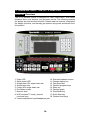
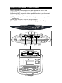
5. UNDERSTAND THE S775 DISPLAY ............................................... 36
DISPLAY Overview .............................................................................. 36
DISPLAY Specications ....................................................................... 37
DISPLAY Windows ............................................................................... 37
DISPLAY Keys ...................................................................................... 37
6. OPERATE THE PRODUCT ............................................................. 39
OPERATION Quick Start ..................................................................... 39
OPERATION Start a Workout Program ............................................... 39
OPERATION Display ........................................................................... 39
OPERATION Cool Down ..................................................................... 41
OPERATION Workout Programs ......................................................... 41
OPERATION User Preferences and Component Versions................... 44
7. ABOUT HEART RATE DETECTION ................................................ 45
HEART RATE Telemetry ...................................................................... 45
HEART RATE Contact ......................................................................... 45
8. GUIDELINES FOR EXERCISE ....................................................... 46
9. ACCESSORIES ............................................................................... 47
ACCESSORIES Entertainment Cap .................................................... 48
ACCESSORIES MYE Wireless TV Audio_Channel Receivers ............ 49
10. MAINTENANCE ............................................................................. 51
MAINTENANCE Messages .................................................................. 51
MAINTENANCE Lubrication ................................................................ 52
MAINTENANCE Inspect Belt ............................................................... 53
MAINTENANCE Schedule ................................................................... 54
MAINTENANCE Task List (Pinnacle Trainer) ....................................... 55
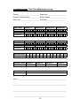
MAINTENANCE One-Year Maintenance Log ...................................... 56
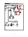
MAINTENANCE Electronics Block Diagram ........................................ 57

2
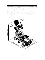
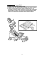
1. INTRODUCTION
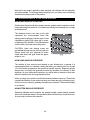
Congratulations on your purchase of one of the nest exercise products on the
market today, the SportsArt S775 pinnacle trainer. Constructed of high quality
materials and designed for years of reliable usage, this product was made to
become an integral part of your commercial tness venue.
Before this product is assembled or operated, we recommend that you familiarize
yourself with this manual. Understanding the correct assembly and operation of
this product will help ensure that exercisers obtain their tness goals safely and
successfully.
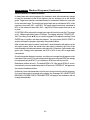
L
R

3
2. SAFETY PRECAUTIONS
Your SportsArt pinnacle trainer was designed and built for optimum safety. However
certain precautions apply whenever you use your pinnacle trainer.
Please read the entire manual before assembly and operation. Also, please note the
following safety precautions:
● Please read the instructions carefully and install the pinnacle trainer as instructed.
● Assemble and operate the pinnacle trainer on a solid, level surface. DO NOT use
outdoors or near water.
● Never allow children on or near the pinnacle trainer.
● Check the pinnacle trainer before every use. Make sure all parts are assembled,
and all fasteners are tightened. DO NOT use the pinnacle trainer if the unit is
disassembled in any way.
● Keep your hands away from moving parts.
● Wear proper workout clothing; DO NOT wear loose clothing. DO NOT wear
shoes with leather soles or high heels. Tie all long hair back. DO NOT go barefoot
on this product.
● Be careful when mounting and dismounting the unit.
● The pinnacle trainer may or may not stop immediately if an object becomes
caught or impedes normal motion.
● DO NOT use any accessories that are not specically recommended by the
manufacturer. Such parts might cause injuries or cause the unit to fail.
● Close supervision is necessary when this pinnacle trainer is used by, on, or near
children, invalids, or disabled persons.
● Use this pinnacle trainer only for its intended use as described in this manual.
● Never operate this pinnacle trainer if it has been damaged in any way. If it is not
working properly, or has been dropped or damaged, contact your dealer.
● Keep all air ventilation areas free of blockage.
● Never drop or insert any object into any opening.
● DO NOT operate where aerosol (spray) products are being used or where oxygen
is being administered.
● The general user weight limit for this pinnacle trainer is 227kg (500lb). Note that
at resistance level 40 this product meets standards for users of up to 150kg (330lb).
● This pinnacle trainer is not intended for use by persons (including children)
with reduced physical, sensory or mental capabilities, or lack of experience
and knowledge, unless they have been given supervision or instruction
concerning use of this pinnacle trainer by a person responsible for their
safety.
● Children should be supervised to ensure that they do not play with the
pinnacle trainer.

4
2. SAFETY PRECAUTIONS (CONTINUED)
Caution
If you feel any pain or abnormal sensation, STOP YOUR WORKOUT and
consult your physician immediately. Work within your recommended exer-
cise level. DO NOT work to exhaustion.
Before beginning any exercise program, you should consult with your doc-
tor. It is recommended that you undergo a complete physical examination.
DO NOT step onto the highest footplate rst. While holding onto supports
for stability, step onto the lowest footplate.
Note: This equipment has been tested and found to comply with the limits
for a digital device, pursuant to part 15 of the FCC Rules. These limits are
designed to provide reasonable protection against harmful interference in
a residential installation. This equipment generates, uses, and can radiate
radio frequency energy and, if not installed and used in accordance with
the instructions, may cause harmful interference to radio communications.
However, there is no guarantee that interference will not occur in a particu-
lar installation. If the user desires to correct such interference, it is at the
user’s own expense.
Warning
Heart rate monitoring systems may be inaccurate. Over exercise may
result in serious injury or death. If you feel faint, stop exercise immediately
and consult a medical physician.

5
2. CONSIGNES DE SÉCURITÉ IMPORTANTES
• Votre pinnacle croix trainer SportsArt a été conçu et fabriqué an
d’assurer une sécurité optimale. Cependant certaines précautions
s’appliquent chaque fois que vous utilisez votre pinnacle croix trainer de
course.
• Lisez entièrement le manuel avant l’assemblage et l’utilisation. Veuillez
aussi noter les consignes de sécurité suivantes:
• Veuillez lire attentivement les instructions et installer l’ pinnacle croix
trainer de course selon les instructions.
• Assemblez et faites fonctionner l’ pinnacle croix trainer sur une surface
solide et plane; NE PAS l’utiliser à l’extérieur ou près de l’eau.
• En aucun cas, ne laissez des enfants à proximité ou sur l’ pinnacle croix
trainer.
• Vériez l’ pinnacle croix trainer de course avant chaque utilisation.
Assurez-vous que toutes les pièces sont assemblées, et que tous les élé-
ments de xation sont serrés. NE PAS utiliser l’ pinnacle croix trainer de
course si l’appareil est démonté de quelque façon.
• Gardez vos mains loin des pièces mobiles.
• Portez des vêtements d’entraînement appropriés; NE PORTEZ PAS de
vêtements amples. NE PORTEZ PAS de chaussures à semelles en cuir
ou à talons hauts. Attachez les cheveux longs. Ne marchez pas pieds nus
sur l’appareil.
• Soyez prudent lors du montage et démontage de l’appareil.
• Le pinnacle croix trainer peut s’arrêter ou ne s’arrêter pas immédiate-
ment si quelque chose obstacle le mouvement.
• NE PAS utiliser d’accessoire non spéciquement recommandé par le
fabricant. Car cela pourraient provoquer des blessures ou entraîner une
panne de l’appareil.
• Une surveillance étroite est nécessaire quand l’ pinnacle croix trainer
est utilisé par ou à proximité d’enfants, de malades ou de personnes hand-
icapées.
• Utilisez l’ pinnacle croix trainer de course uniquement pour l’usage
prévu dans ce manuel.
• N’utilisez jamais l’ pinnacle croix trainer de course s’il a été endommagé
de quelque façon que ce soit. S’il ne fonctionne pas correctement, ou s’il
est tombé ou endommagé, contactez votre vendeur.
• Veillez à ce qu’aucun orice de ventilation ne soit obstrué.
• Ne faites jamais tomber ou n’insérez jamais d’objet dans les orices.
• NE PAS l’utiliser là où des produits aérosols (vaporisés) sont utilisés ou
lorsque de l’oxygène est administré.
• La limite de poids de l’utilisateur pour cet l’ pinnacle croix trainer est de
227 Kgs (500 lbs). Remarquez que la résistance de 40 convient jusqu’à
150kgs (330 lbs).
• NE PAS transporter l’ pinnacle croix trainer de course par le cordon
d’alimentation et n’utilisez pas le cordon comme poignée.
• Maintenez le cordon éloigné de toute surface chaude.
• Débranchez l’appareil de la prise avant l’entretien ou la suppression de
toute pièce.

6
2. CONSIGNES DE SÉCURITÉ (SUITE)
• Pour diminuer le risque de choc électrique, débranchez toujours ce l’
pinnacle croix trainer de course de la prise de courant, immédiatement
après utilisation et avant le nettoyage.
Ce pinnacle croix trainer n’est pas destiné à être utilisé par des personnes (y compris
des enfants) dont les capacités physiques, sensorielles ou mentales sont réduites
ou qui ne disposent pas de l’expérience ou du savoir nécessaires, sauf si celles-ci
ont au préalable été formées eu égard à l’utilisation de ce pinnacle croix trainer par
une personne responsable de leur sécurité. Les enfants doivent être encadrés an
d’empêcher qu’ils ne jouent avec l’ pinnacle croix trainer.
ATTENTION
Si vous ressentez une douleur ou si vous avez une sensation anormale,
ARRÊTEZ VOTRE ENTRAÎNEMENT et consultez immédiatement votre médecin.
Entraînez-vous à votre niveau d’exercice recommandé. NE PAS s’entraîner jusqu’à
l’épuisement.
Avant de commencer un programme d’exercice, vous devriez consulter votre
médecin. Il est recommandé de faire un examen physique complet.
Remarque: Ce matériel a été testé et déclaré conforme aux normes des appareils
digitaux de Classe B, conformément à la partie 15 du Règlement de la FCC. Ces
limites sont conçues pour offrir une protection raisonnable contre les interférences
nuisibles dans une installation résidentielle. Cet appareil génère, utilise, et peut
diffuser des signaux radioélectriques, et, s’il n’est pas installé et utilisé conformément
aux instructions, peut provoquer des interférences nuisibles aux communications
radio. Cependant, il n’y a aucune garantie que des interférences ne se produiront
pas dans une installation particulière.
Si l’utilisateur désire corriger les interférences, ces corrections seront à la charge de
l’utilisateur.
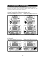
Dans ce manuel, les mots “gauche” et “droit” sont utilisés en référence aux pièces et
au produit. Comme tels, les mots “gauche” et “droit” font respectivement référence
aux côtés gauche et droit de l’exerciseur. De même pour plus de concision, le
mot est utilisé dans certains cas où des rondelles, des vis et autres matériels sont
associés.
ATTENTION!
Les systèmes de surveillance de la fréquence cardiaque peuvent s’avérer imprécis.
Un entraînement excessif risque de nuire sérieusement à la santé ou d’entraîner la
mort. En cas d’étourdissement, arrêtez immédiatement l’entraînement.
• Un branchement incorrect du connecteur de mise à la terre de
l’équipement risque d’entraîner un choc électrique. En cas de doute sur
la mise à la terre correcte de l’ pinnacle croix trainer, faites appel à un
technicien ou un électricien qualié. NE PAS modier la che fournie avec
l’elliptique, si elle ne correspond pas à la prise, faites installer une prise
adéquate par un technicien qualié.
• Les enfants doivent être encadrés an d’empêcher qu’ils ne jouent avec
l’ pinnacle croix trainer.

7
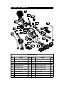
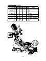
3. LIST OF PARTS
Assembly Parts
No. Name Qty. No. Name Qty.
A1 Display neck assembly 1 A10 Left support lower cover 1
A2 Pedestal assembly 1 A11 Right support lower cover 1
A3 Main frame 1 A12 Feeder cord 1
A4 Right glide track 1 A13 Right handle cover 1
A5 Left glide track 1 A14 Left handle cover 1
A6 Rear adjustment base 1 A15 Connecting board 1
A7 Right support 1 A16 Right pedal 1
A8 Left support 1 A17 Left pedal 1
A9 Front cover 1 A18 Bottle holder 1

8
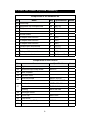
Components in the Hardware Kit
No. Name Qty. Specication Notes
30 Cover cap 3
31 Mushroom top Phillips screw 20 M4*L16
32 Phillips screw 4 M5*L15
33 Ground wire 1
Screw socket 20
L shaped Allen wrench 1 (M4)
L shaped Allen wrench 1 (M5)
L shaped Allen wrench 1 (M6)
Double open end wrench 2 (13*17)
Double open end wrench 1 (17*23)
T shaped Allen wrench 1 (M5)
Screwdriver shank 1 Phillips and at
Components on the Product
No. Name Specication Notes
51 Right rear cover
52 Mushroom top Phillip screw M4*L16
53 Rear footplate
54 Left rear cover
56
Inner hex screw M8*P1.25*L25
Serrated washer D22*d8.5*t2.0*28T
57
Hex head screw M8*P1.25*L100
Flat washer D17*d8.3*t2
Bushing ØD12*d8*L82
58 Left/Right mount
59 Cover cap ØD23*t8.8
60 Front cover
61 Mushroom top Phillip screw M4*L16
62 Top cover
3. LIST OF PARTS (CONTINUED)

9
Components on the Product
No. Name Specication Notes
63
Nylon hex lock nut M10
Flat washer D26*d10.5*t3
Axle F M10*L60
64
Axle C M10*L78
Bushing B ØD20*d12.2*L14.5
Nylon hex lock nut M10
65 Fan cover
66 Mushroom top Phillip screw M4*L16
67 Bevelled head inner hex screw M6*L15
68 Pedestal cover
69 Mushroom top Phillip screw M4*L16
70
Inner hex screw M8*P1.25*L25
Serrated washer D18*d8.5*t2.0*19T
71 Connecting board
73
Serrated washer D20*d6.2*t2.0*19T
Inner hex screw M6*P1.0*L15
75 Phillip screw M5*P0.8*L10
76 Pedestal mount
77 Axle E
78 Mushroom top Phillip screw Ø8.5 M4*L16
79 Mushroom top inner hex screw M5*L16
80
Spring washer M8
Serrated washer D18*d8.5*t2.0*19T
Mushroom top inner hex screw M8*P1.25*L15
3. LIST OF PARTS (CONTINUED)

10
4. ASSEMBLE THE PRODUCT
Follow instructions below to assemble this product. Note that in this manual
the words “left” and “right” are used to refer to the product and its parts. As
such, these designations correspond to the “left” and “right” sides of a person
in position to exercise on this product. Also, for brevity, the word “screws” is
used where screws, washers, and other hardware may be involved.
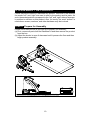
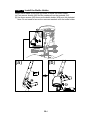
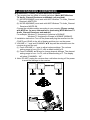
STEP 0 Prepare for Assembly
Please follow instructions (a) through (b) to prepare for assembly.
(a) First, remove all parts and the hardware kit and then remove the product
from the box.
(b) Adjust the leveler in area A downward until it presses the floor and then
begin product assembly.

11
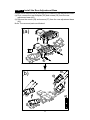
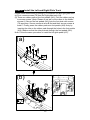
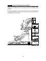
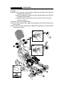
STEP 1 Install the Rear Adjustment Base
Please follow instructions (a) through (d) to install the rear adjustment base.
(a) First, remove the rear footplate (53) and screws (52) from the rear
adjustment base (A6)
(b) Remove the mount (58) and screws (57) from the rear adjustment base
(A6)
Note: The removed parts are bilateral.
(b)
(a)

12
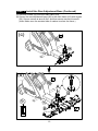
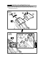
STEP 1 Install the Rear Adjustment Base (Continued)
(c) Remove screws (56) from the main frame (A3).
(b) Secure the rear adjustment base (A6) to the main frame (A3) with screws
(56). Secure screws at area A first. and then secure screws at area B.
(Note: Make sure the serrated side of washer touches the frame.)
(d)
A
B
(c)
B

13
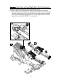
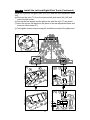
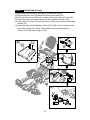
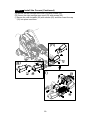
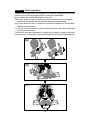
STEP 2 Install the Left and Right Glide Track
Please follow instructions (a) through (j) to install the left and right glide track.
(a) First, remove screws (79) from the right glide track (A4).
(b) There are rubber pads on the foot pedals (A16). Fold the rubber pad up
to access screws. (Note: Please do not pull out the nibes in the middle
at area A.) Secure the foot pedals (A16) onto the foot plate with screws
(79) as shown. Secure screws at area B first and then secure screws at
area C. Finally, press the rubber pads onto foot pedals (A16) firmly by
inserting the nibs on the rubber pads through the holes in the foot pedals
(A16). Make sure that the nibs protrude through the foot pedals (A16).
Note: Follow the same procedure to install the left glide pedal (A17).
(a)
(b)

14
STEP 2 Install the Left and Right Glide Track
(c) First, remove the covers (59) (60) (62) from the main frame (A3).
(d) Remove the axle (63A) and the nut (63) from the main frame (A3). (Note:
The axle may drop off.)
(c)
(d)

15
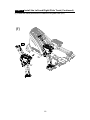
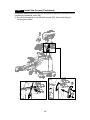
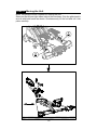
STEP 2 Install the Left and Right Glide Track (Continued)
Install the right glide track (A4) and the main frame (A3)
(e) First, loosen 3 piece screws from area (d1) covers (Do not reomove
these screws) and then place the right glide track (A4) on the main frame
(A3) and insert the axle (63) into the main frame (A3) and the right glide
track (A4), and loosely secure it with nut. Do not tighten the nut. (Fully
tighten the nut only after STEP 2 is completed.)
d1
(e)

16
STEP 2 Install the Left and Right Glide Track (Continued)
(f) Follow the same procedure to install the left glide track (A5).
L
(f)

17
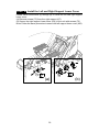
STEP 2 Install the Left and Right Glide Track (Continued)
Install the right and left glide track (A4) (A5) and the rear adjustment base
(A6).
(g) Remove the axle (77) from the right and left glide track (A4) (A5) and
insert the ball socket.
(h) Secure the ball socket and the glide track with the axle (77) as shown.
(i) Insert the mount (58) back into the place in the rear adjustment base and
secure it with screws (57).
(j) Fully tighten three screws at area (d1) and all the screws of the glide track.
(j)
d1
(i)
(g)
(h)

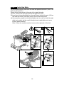
18
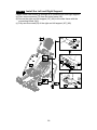
STEP 3 Install the Belts
Do not cross the belts, make sure the belts are parallel as shown. (Note: The
belt are side-specific.)
Please follow instructions (a) through (d) to install the belts.
(a) First, remove the axle (64) from the left glide track (A5).
(b) Insert two belts and bushing from the main frame through the axle. (Follow
the order as shown.) and then secure the nut back into place.
(d) Have another people to hold the left glide track in order to install the right
glide track easlily, but be careful the glide track might glide and cause
injuries when installing.
Note: Follow the same procedure to secure the right side of the belt.
(c)
(a)
(b)
(d)

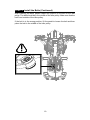
19
STEP 3 Install the Belts (Continued)
After installing the belts, please inspect the position of the belt on the idler
pulley. The belt should be in the middle of the idler pulley. Make sure that the
belt is not outside of the idler pulley.
If the belt is in the wrong position, lift the pedal to loosen the belt and then
place the belt in the middle of the idler pulley.

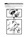
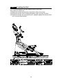
20
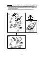
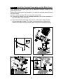
STEP 4 Install the Display Neck and Pedestal Assembly
Please follow instructions (a) through (l) to install the display neck and
pedestal assembly.
(a) First, remove the fan cover (65) and screws (66) (79) from the display
neck assembly (A1)
(b) Remove the pedestal mount (76), pedestal cover (68) and screws (67)
(69) from the pedestal assembly (A2).
(a)
(b)
La page est en cours de chargement...
La page est en cours de chargement...
La page est en cours de chargement...
La page est en cours de chargement...
La page est en cours de chargement...
La page est en cours de chargement...
La page est en cours de chargement...
La page est en cours de chargement...
La page est en cours de chargement...
La page est en cours de chargement...
La page est en cours de chargement...
La page est en cours de chargement...
La page est en cours de chargement...
La page est en cours de chargement...
La page est en cours de chargement...
La page est en cours de chargement...
La page est en cours de chargement...
La page est en cours de chargement...
La page est en cours de chargement...
La page est en cours de chargement...
La page est en cours de chargement...
La page est en cours de chargement...
La page est en cours de chargement...
La page est en cours de chargement...
La page est en cours de chargement...
La page est en cours de chargement...
La page est en cours de chargement...
La page est en cours de chargement...
La page est en cours de chargement...
La page est en cours de chargement...
La page est en cours de chargement...
La page est en cours de chargement...
La page est en cours de chargement...
La page est en cours de chargement...
La page est en cours de chargement...
La page est en cours de chargement...
La page est en cours de chargement...
-
 1
1
-
 2
2
-
 3
3
-
 4
4
-
 5
5
-
 6
6
-
 7
7
-
 8
8
-
 9
9
-
 10
10
-
 11
11
-
 12
12
-
 13
13
-
 14
14
-
 15
15
-
 16
16
-
 17
17
-
 18
18
-
 19
19
-
 20
20
-
 21
21
-
 22
22
-
 23
23
-
 24
24
-
 25
25
-
 26
26
-
 27
27
-
 28
28
-
 29
29
-
 30
30
-
 31
31
-
 32
32
-
 33
33
-
 34
34
-
 35
35
-
 36
36
-
 37
37
-
 38
38
-
 39
39
-
 40
40
-
 41
41
-
 42
42
-
 43
43
-
 44
44
-
 45
45
-
 46
46
-
 47
47
-
 48
48
-
 49
49
-
 50
50
-
 51
51
-
 52
52
-
 53
53
-
 54
54
-
 55
55
-
 56
56
-
 57
57


SportsArt S775 Le manuel du propriétaire
- Catégorie
- Fitness, gymnastique
- Taper
- Le manuel du propriétaire
dans d''autres langues
- English: SportsArt S775 Owner's manual
Documents connexes
-
SportsArt G875 Le manuel du propriétaire
-
-
-
-
-
-
-
-
-