

MXR Series – Installation and User Guide
Document Number: 81317-4
Issue: 2
Spellman High Voltage Electronics Limited | +44 (0)1798 877000 | hvsales@spellmanhv.co.uk | Broomers Park, Pulborough, W. Sussex, UK. RH20 2RY
TEMPLATE: 40776 ISS B | ECN I-10887 | DATE: 05/11/2021
QA/ENG/SAL
© 2021 Spellman High Voltage Electronics Corporation
Page 2 of 12
Change History
Contents
1. Unit Description ..........................................................................................................................................5
1.1 Unit Ratings ......................................................................................................................................5
1.1.1 Power Input..................................................................................................................................5
1.1.2 HV Output ....................................................................................................................................5
1.2 Environmental conditions..................................................................................................................5
2. Safety .........................................................................................................................................................6
2.1 Meaning of Symbols .........................................................................................................................6
2.2 Regulatory Approvals .......................................................................................................................6
3. Installing the Unit........................................................................................................................................7
3.1 Initial Inspection ................................................................................................................................7
3.2 Mechanical Installation .....................................................................................................................7
3.3 Electrical Installation .........................................................................................................................7
4. Connections and Unit Operation ................................................................................................................8
4.1 HV Ouput connector and mating cable .............................................................................................8
4.2 Analog version - Connections and Operation ...................................................................................9
4.3 Digital Version - Connections and Operation ................................................................................ 10
4.3.1 Power input connector .............................................................................................................. 10
4.3.2 Control connector ..................................................................................................................... 10
4.4 HV On Indicators ........................................................................................................................... 11
Appendix A - Mechanical layout ...................................................................................................................... 12
ISSUE
DATE
NAME
SECTION
CHANGE
A
N/A
All
Created from 80888-1 issue B
B
10/Apr/2018
1
HV output cable paragraph added.
C
15/Sep/2020
All
Revise and reformat for user guide
1
5/Mar/2021
JS
1
2.1
Mating cable ordering info and specs added
Regulatory approvals info added
2
8/Nov/2021
JS
All
1.1.1
4
4
4.2
4.3.2
New document template
Added peak reversing current info
Connections and operation chapters and tables merged
Connectors and mating part numbers, pin indication and other info added
Analog unit connector info corrected from Molex KK5.08 to Samtec FWS
RS485 communication option added

MXR Series – Installation and User Guide
Document Number: 81317-4
Issue: 2
Spellman High Voltage Electronics Limited | +44 (0)1798 877000 | hvsales@spellmanhv.co.uk | Broomers Park, Pulborough, W. Sussex, UK. RH20 2RY
TEMPLATE: 40776 ISS B | ECN I-10887 | DATE: 05/11/2021
QA/ENG/SAL
© 2021 Spellman High Voltage Electronics Corporation
Page 3 of 12
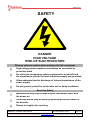
SAFETY
DANGER
HIGH VOLTAGE
RISK OF ELECTROCUTION
Observe extreme caution when working with this equipment
High voltage power supplies must always be connected to
protective earth
Do not touch connections unless equipment is turned off and
the capacitance of both the load and power supply are grounded
Allow adequate time for discharge of internal capacitance of the
power supply
Do not ground yourself or work under wet or damp conditions
Servicing Safety
Maintenance may require removing the Instrument cover with
the power on
Servicing should only be done by qualified personnel aware of
the hazards
Return to supplier for servicing

MXR Series – Installation and User Guide
Document Number: 81317-4
Issue: 2
Spellman High Voltage Electronics Limited | +44 (0)1798 877000 | hvsales@spellmanhv.co.uk | Broomers Park, Pulborough, W. Sussex, UK. RH20 2RY
TEMPLATE: 40776 ISS B | ECN I-10887 | DATE: 05/11/2021
QA/ENG/SAL
© 2021 Spellman High Voltage Electronics Corporation
Page 4 of 12
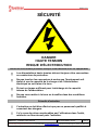
SÉCURITÉ
DANGER
HAUTE TENSION
RISQUE D'ÉLECTROCUTION
Observez une extrême prudence lorsque vous travaillez avec cet équipement
Les alimentations haute tension doivent toujours être connectées
au conducteur de protection.
Ne pas toucher les connexions à moins que l'équipement soit
éteint et que la capacité de la charge et de l'alimentation
électrique ne soit mise à la terre.
Prévoir un temps suffisant pour la décharge de la capacité
interne de l'alimentation.
Ne pas vous mettre à la terre ou travailler dans des conditions
humides.
Sécurité d'entretien
L'entretien ne doit être effectué que par un personnel qualifié et
conscient des dangers.
Il n'y a pas de piéce remplaçables par l'utilisateur dans l'unité,
retourner au fournisseur pour l'entretien.

MXR Series – Installation and User Guide
Document Number: 81317-4
Issue: 2
Spellman High Voltage Electronics Limited | +44 (0)1798 877000 | hvsales@spellmanhv.co.uk | Broomers Park, Pulborough, W. Sussex, UK. RH20 2RY
TEMPLATE: 40776 ISS B | ECN I-10887 | DATE: 05/11/2021
QA/ENG/SAL
© 2021 Spellman High Voltage Electronics Corporation
Page 5 of 12
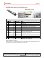
1. Unit Description
The HV power supply units MXR20PN24 and MXR30PN24 are intended for use in mass spectrometry,
electron microscopy, capillary electrophoresis and electrostatic printing applications, they consist of one
aluminium chassis containing the high voltage power supply.
Control and monitoring of the units is accomplished via either analogue controls on the standard unit or
serial communication interface on the DCC2 option:
Analogue for MXR20PN24 and MXR30PN24
Serial for MXR20PN24/DCC2 and MXR30PN24/DCC2
A 2 meters HV output mating cable is available to order, with the following part number: HVC30/1S/1279,
see section 4.1 for further details.
1.1 Unit Ratings
1.1.1 Power Input
Input Voltage: 24 Vdc ± 10%
Input Current: ≤1.25 A nominal continuous
≤4.5 A peak during reversing
1.1.2 HV Output
Unit
Output Voltage range
Max Output Current
MXR20
-20 kV to +20 kV
300 µA
MXR30
-30 kV to +30 kV
300 µA
1.1.3 Protection
Current limit: ±330uA +10% -5%
Protection: Arc and short-circuit protected
1.2 Environmental conditions
Operating Temperature: 10°C to +50°C
Storage Temperature: -35°C to +85°C
Humidity: 0% to 80% RH (non-condensing)
Altitude: 0 to 2000m ASL

MXR Series – Installation and User Guide
Document Number: 81317-4
Issue: 2
Spellman High Voltage Electronics Limited | +44 (0)1798 877000 | hvsales@spellmanhv.co.uk | Broomers Park, Pulborough, W. Sussex, UK. RH20 2RY
TEMPLATE: 40776 ISS B | ECN I-10887 | DATE: 05/11/2021
QA/ENG/SAL
© 2021 Spellman High Voltage Electronics Corporation
Page 6 of 12
2. Safety
The HV outputs of the units are considered hazardous, the protection against electric shock provided
by the units may be impaired if the units are not operated in accordance with the instructions in this
manual.
The units are contained in an earthed case with a screened HV output cable and the HV output cable
must be terminated safely before the units are operated.
This unit must be sourced with a double insulated or SELV 24 V dc supply.
The unit shall be properly bonded to the main protective earthing termination in the end product.
The units have been evaluated for use in a Pollution Degree 2, Installation Category II environment.
Consideration should be given to conducting the following tests with the unit installed in the end product:
a. Permissible Limits Tests with the unit installed in the end product.
b. Temperatures on accessible surfaces.
The units have not been the subject of a risk analysis; this should be done in the end product application.
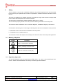
2.1 Meaning of Symbols
SYMBOL
MEANING
Refer to manual before operating
Caution, possibility of electric shock
Protective conductor terminal (PE)
2.2 Regulatory Approvals
The unit is designed to meet the requirements of EN 61010-1, UL 61010-1 and CAN/CSA-22.2 No.
61010-1. Please consult datasheet or the factory for further approval information.

MXR Series – Installation and User Guide
Document Number: 81317-4
Issue: 2
Spellman High Voltage Electronics Limited | +44 (0)1798 877000 | hvsales@spellmanhv.co.uk | Broomers Park, Pulborough, W. Sussex, UK. RH20 2RY
TEMPLATE: 40776 ISS B | ECN I-10887 | DATE: 05/11/2021
QA/ENG/SAL
© 2021 Spellman High Voltage Electronics Corporation
Page 7 of 12
3. Installing the Unit
3.1 Initial Inspection
Inspect the package exterior for evidence of damage due to handling in transit. Notify the carrier and
Spellman immediately if damage is evident. Do not destroy or remove any of the packing material used
in a damaged shipment.
After unpacking, inspect the panel and chassis for visible damage.
Note: Failure to comply with the above could compromise the safe operation of the unit and invalidate
the warranty.
3.2 Mechanical Installation
The MXR units must be fitted in the end product and secured in position using screws.
The units must not be used in an environment with a level of pollution worse than Pollution Degree 2.
The units are intended for use as a component and no surface of the units should be accessible in the
end product.
3.3 Electrical Installation
The units should only be connected to a Category II environment, the units are not intended for
connection to the mains. The power for the units should be sourced from a UL recognised double
insulated or SELV 24 V dc supply. There is no external fuse.
The units shall be properly bonded to the main protective earthing termination in the end product via the
chassis.
The input and output connectors are not intended for field connections and should only be connected to
internal wiring in the end product. All external circuits connected to High Voltage outputs shall be
Double/Reinforced insulated from any accessible parts.

MXR Series – Installation and User Guide
Document Number: 81317-4
Issue: 2
Spellman High Voltage Electronics Limited | +44 (0)1798 877000 | hvsales@spellmanhv.co.uk | Broomers Park, Pulborough, W. Sussex, UK. RH20 2RY
TEMPLATE: 40776 ISS B | ECN I-10887 | DATE: 05/11/2021
QA/ENG/SAL
© 2021 Spellman High Voltage Electronics Corporation
Page 8 of 12
4. Connections and Unit Operation
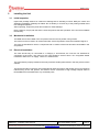
4.1 HV Ouput connector and mating cable
High Voltage output is via a GES HB30 high voltage receptacle for both analog
and digital product versions. GES Part number: 7331051
A 2 meters HV output mating cable is available to order, with the following part number:
Power input cable part number: HVC30/1S/1279
Length: 2m
Different cable lengths are available upon request.
This cable is screened, and the shield provides the load return ground.
Mating Cable Details:
Part
Manufacturer
Part description
Manufacturer part
number
HV cable
GES
HS30/Au PTFE
7331150
Plug, cable mount
GES
HV cable, 30kVDC, coaxial cable
3330007
Note: Customised versions of the MXR units can be developed with an HV output cable encapsulated
into the unit, UL style 3873. Please consult with factory.

MXR Series – Installation and User Guide
Document Number: 81317-4
Issue: 2
Spellman High Voltage Electronics Limited | +44 (0)1798 877000 | hvsales@spellmanhv.co.uk | Broomers Park, Pulborough, W. Sussex, UK. RH20 2RY
TEMPLATE: 40776 ISS B | ECN I-10887 | DATE: 05/11/2021
QA/ENG/SAL
© 2021 Spellman High Voltage Electronics Corporation
Page 9 of 12
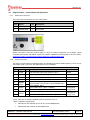
4.2 Analog version - Connections and Operation
Both power input and control are via a 12-way Samtec connector:
Manufacturer : Samtec Series: FWS Part number : FWS 12-04-T-S-RA
pin#
Signal
I/O
Description
Levels
1
IMON
O
Current Monitor
0 to 10V for 0 to 500uA, always positive, Zout = 10kΩ,
Accuracy ±5%
2
+24VDC
I
DC in
3
VMON
O
Voltage Monitor
0V to 10V for 0 to 20kV (MXR20) or 30kV (MXR30)
always positive. Zout = 10kΩ, Accuracy ±2%
4
NC
5
NC
6
NC
7
VSET
I
Voltage Control
0V to 10V for 20kV (MXR20) or 30kV (MXR30), always
positive Zin >1MΩ, Accuracy ±2%
8
POLSET
I
Polarity Change
TTL: Low = positive HV
High/open = negative HV
9
SGND
I/O
Signal ground
10
+24VDC RTN
I
DC in return
11
NC
12
POL STATUS
O
Polarity monitor
positive HV: 0V (<200mV), source 1.5kΩ
negative HV: +24V, source 2.2kΩ
Mating connector is not provided.
Mating receptacle: for example, Molex KK 508 3001 part number 10-01-1124, with Molex crimps: KK
396 part number: 08-55-0106, and wire gauge of 18 to 26 AWG.

MXR Series – Installation and User Guide
Document Number: 81317-4
Issue: 2
Spellman High Voltage Electronics Limited | +44 (0)1798 877000 | hvsales@spellmanhv.co.uk | Broomers Park, Pulborough, W. Sussex, UK. RH20 2RY
TEMPLATE: 40776 ISS B | ECN I-10887 | DATE: 05/11/2021
QA/ENG/SAL
© 2021 Spellman High Voltage Electronics Corporation
Page 10 of 12
4.3 Digital Version - Connections and Operation
4.3.1 Power input connector
24V power input connections are via a 2-way Molex
Manufacturer: Molex Series: Mini-fit Jr Part number : 39-30-1022
pin#
Signal
I/O
Description
1
+24VDC
I
DC in
2
+24VDC RTN
I
DC in return
Please see Molex connector product page for range of mating receptacles (for example, Molex
receptacle part number: 39012020, crimps part number: 39000038, and wire gauge of 18 to 24 AWG):
https://www.molex.com/molex/products/part-detail/pcb_headers/0039301022
4.3.2 Control connector
The serial communication link (default RS232, see details below about RS485 options) is via a 10 way
“IDC ribbon cable” connector. See table below for pin out details.
Manufacturer: 3M Series: 3000 Part number: N3793-5302RB
pin#
Signal
I/O
Description
Level
1
Z/TXD
O
Transmit data (output) with respect to pin 2
Serial
2
GND
I/O
Serial signal ground return (if required)
RTN (see *)
3
Y/RXD
I
Receive data (input) with respect to pin 2
Serial
4
-
NC
5
RS485
mode**
-
Link these two pins together for RS485
communication. Only for Rev ≥ 3D for MXR20 and ≥
2B for MXR30. See **
6
-
7
INTER
LOCK
I
Opto-isolator input – [0mA = INHIBIT]
3V3 @ 6mA
5V @ 10mA
8
I
Opto-isolator signal return
9
POLSET
I
Polarity Change Signal opto-isolator input 0mA = -VE
3V3 @ 6mA
5V @ 10mA
10
I
Polarity Change Signal opto-isolator signal return
* Note: Take care in choosing suitable ground connection for pin 2.
**Note 2: RS485 is supported for:
• Revision 3D and onwards (4D or 4E etc.) for the MXR20 units
• Revision 2B and onwards for the MXR30 units

MXR Series – Installation and User Guide
Document Number: 81317-4
Issue: 2
Spellman High Voltage Electronics Limited | +44 (0)1798 877000 | hvsales@spellmanhv.co.uk | Broomers Park, Pulborough, W. Sussex, UK. RH20 2RY
TEMPLATE: 40776 ISS B | ECN I-10887 | DATE: 05/11/2021
QA/ENG/SAL
© 2021 Spellman High Voltage Electronics Corporation
Page 11 of 12
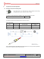
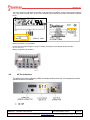
The unit’s revision is indicated on the label, under the field “Prod Status” for the units supporting RS232
only, and under the field “Rev” for the units supporting both RS232 and RS485. See labels examples
below.
Mating connector is not provided.
Please see 3M product page for range of mating receptacles (for example 3M part number
89110-0101HA)
Mating receptacle pin positions:
4.4 HV On Indicators
The MXR units use the following LEDs to indicate polarity when the unit is powered, and the
optional interlock is enabled:
• HV +VE
• HV -VE

MXR Series – Installation and User Guide
Document Number: 81317-4
Issue: 2
Spellman High Voltage Electronics Limited | +44 (0)1798 877000 | hvsales@spellmanhv.co.uk | Broomers Park, Pulborough, W. Sussex, UK. RH20 2RY
TEMPLATE: 40776 ISS B | ECN I-10887 | DATE: 05/11/2021
QA/ENG/SAL
© 2021 Spellman High Voltage Electronics Corporation
Page 12 of 12
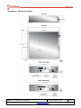
Appendix A - Mechanical layout
-
 1
1
-
 2
2
-
 3
3
-
 4
4
-
 5
5
-
 6
6
-
 7
7
-
 8
8
-
 9
9
-
 10
10
-
 11
11
-
 12
12


dans d''autres langues
- English: Spellman MXR Series User guide
Documents connexes
Autres documents
-
Line 6 POD Go Wireless Le manuel du propriétaire
-
Lupus LUPUSNET LE900 Manuel utilisateur
-
Zoom G71UT Le manuel du propriétaire
-
Chloride Desk POWER 650 Fiche technique
-
Eurotech ReliaGATE 10-20 Le manuel du propriétaire
-
ESAB iCNC Performance CNC Controller Manuel utilisateur
-
Eurotech DynaGATE 10-12 Le manuel du propriétaire
-
kontron FlatClient RCK Le manuel du propriétaire