Red Rock 8469538 Le manuel du propriétaire
- Taper
- Le manuel du propriétaire

Questions, problems, missing parts? Before returning to your retailer, call our customer service
department at 1-888-723-6534, 8 a.m. - 5 p.m. PST, Monday - Friday.
Serial Number Purchase Date
2022 Version N281 & N287 [email protected]
48” / 54” TOW-BEHIND
LAWN SWEEPER
ATTACH YOUR RECEIPT HERE

2
TABLE OF CONTENTS
Package Contents ..................................................................................................... 3
Hardware Contents ................................................................................................... 4
Safety Information .................................................................................................... 5
Assembly Instructions ........................................................................................ 6 - 11
Operating Instructions ............................................................................................. 12
Maintenance ..................................................................................................... 13 - 14
Parts Drawing .......................................................................................................... 16
Parts List .......................................................................................................... 17 - 18
Warranty .................................................................................................................. 19

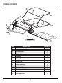
PACKAGE CONTENTS
3
J
K
L
C
M
D
N
I
E
F
G
A
B
1
1
1
1
1
1
1
2
2
1
2
2
Connecting Rod
Bag Frame Strap
Straight Hitch Bracket
Upper Hopper Side Tube
Lower Hopper Side Tube
Sweeper Housing Assembly
Hopper Support Rod
PART QUANTITY
Hitch Bracket
Righthand Hitch Tube (RH)
H
2Rear Hopper Tube
Lefthand Hitch Tube (LH) 1
Handle Assembly
Hopper Bag
Bag Arm Tube
O 1Rope
A
B
C
D
E
F
G
H
I
I
J
K
L
L
M
M
N
N
O
DESCRIPTION
P
P 1Front Support Rod

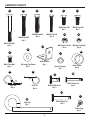
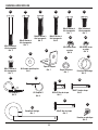
HARDWARE CONTENTS
4
CC DD EE
AA
M8x75 Hex Bolt
Qty. 2
FF
M8x55 Hex Bolt
Qty. 2
M8x40 Hex Bolt
Qty. 2
M6x45 Hex Bolt
Qty. 4
M8x20 Hex Bolt
Qty. 1
M8x16 Hex Bolt
Qty. 1
GG HH
II
JJ
LL
Ø8 Large Flat Washer
Qty. 1
M8 Nylon Lock Nut
Qty. 8
M6 Nylon Lock Nut
Qty. 6
M6x12 Hex Bolt
Qty. 2 Spacer Bushing
Qty. 1
MM
NN OO
Ø2 R Pin
Qty. 4
Hitch Spacer
Qty. 2
Ø3 R Pin
Qty. 5
QQ
RR
PP
Ø9.5x25 Clevis Pin
Qty. 2
Ø6x37 Clevis Pin
Qty. 2
Ø6x42 Clevis Pin
Qty. 2
SS
Hitch Pin
Qty. 1
TT
Plastic Plug
Qty. 4
KK
Angle Bracket
Qty. 1
BB

SAFETY INFORMATION
5
PREPARATION
READ and UNDERSTAND this manual completely before using the Lawn Sweeper.
Operator must read and understand all safety and warning information, operating instructions, maintenance and
storage instructions, before operating this equipment. Failure to properly operate and maintain the lawn sweeper
could result in serious injury to the operator and/or bystanders.
Do not use the sweeper to carry passengers and never sit or stand on the lawn sweeper.
Do not allow children to play on, stand upon, or climb on the lawn sweeper.
Only connect the hopper rope to the tow vehicle. Do not connect the hopper rope to anything else.
Always keep body parts clear from and clothing detached from the sweeper and rope.
Always inspect the sweeper before use to insure that it is in good working condition.
Always check and tighten hardware and assembled parts before operation.
Avoid large holes and ditches when operating the equipment.
Be careful when operating the sweeper on steep grades (hills).
Always operate up and down the slope. Never operate across the face of the slope.
Always operate at reduced speeds on rough terrain, along creeks, ditches and on hillsides.
Do not operate close to creeks, ditches, or public highways.
To avoid personal injury and/or equipment damage DO NOT EXCEED 5 MPH.
Always use caution when loading and unloading the hopper.
Only tow with recommended vehicles (Lawn/Garden Tractors and ATVs).
Always refer to the vehicle owner’s manual for proper towing.
Always secure and lock sweeper to the vehicle hitch before operating.
Always keep hands and feet clear from moving parts while operating the equipment.
Always clear and keep work area clean when operating.
Always wear safety gear, eye protection, gloves, and work boots when operating the sweeper.
WARNING: This product can expose you to chemicals including lead and lead compounds which are known to the State of California to
cause cancer and birth defects or other reproductive harm. For more information, go to www.P65Warnings.ca.gov
WARNING: The warnings, cautions, and instructions outlined in this instruction manual cannot cover all possible conditions or
situations that may occur. It must be understood by the operator that common sense and caution are factors which cannot be built into
this product and must be supplied by the operator.
Before beginning assembly of product, make sure all parts are present. Compare parts with package contents list
and hardware contents list. If any part is missing or damaged, do not attempt to assemble the product.
Tools Required for Assembly (not included): 10 mm, 13 mm and 14 mm Wrenches.

6
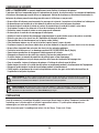
ASSEMBLY INSTRUCTIONS
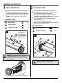
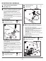
1 Mount Angle Bracket
Remove the four wood splints from brush. These can be
loosened by hand or with a 10mm socket or wrench.
Attach the Angle Bracket (KK) to the sweeper housing (H)
by using the M8x16 Hex Bolt (FF) and the M8 Nylon Lock
Nut (GG). Tighten securely, using 13 mm and 14 mm
wrench.
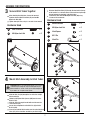
2 Attach Hitch Tubes
CAUTION: Right Hand (RH) and Left Hand (LH) refer to the
drivers’ orientation when operating the vehicle.
Remove the two black hitch tubes (A) & (B) from the box.
Place righthand hitch tube (A) on the right side of the main
housing (H) with the angled end facing inward.
Place a M6x45 Hex Bolt (DD) through the middle hole in
righthand hitch tube (A) and the top hole in the main housing (H).
Fasten the bolt with a M6 Nylon Lock Nut (HH).
Place another M6x45 Hex Bolt (DD) in the hole below the
bolt you just secured.
Fasten with another M6 Nylon Lock Nut (HH).
Repeat these steps for lefthand hitch tube (B) on the other side.
Tighten securely, using 10 mm wrench.
Hardware Used
Hardware Used
CAUTION: Before tightening, make sure the angle bracket
is aligned straight with the sweeper housing, as shown in
the diagram, with the raised end positioned on the opposite
side of the main logo.
KK x 1Angle Bracket
x 1M8x16 Hex Bolt
FF
x 1M8 Nylon Lock Nut
GG
Four wood splints are used to protect the brushes during shipping.
x 4
DD
x 4M6 Nylon Lock Nut
HH
M6x45 Hex Bolt
1
GG
FF
KK
Pay attention to
the direction of
the angle bracket
when installing.
H
2
DD
HH
A
H
B

7
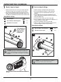
3
ASSEMBLY INSTRUCTIONS
GG
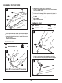
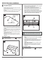
3 Secure Hitch Tubes Together
After attaching the hitch tubes. Secure the two ends
together with two M8x75 Hex Bolts (AA) and two M8
Nylon Lock Nuts (GG).
Tighten loosely for now, using 13 mm and 14 mm wrench.
Hardware Used
Hardware Used
CAUTION: Check to see how high the hitch is on your tractor
or ATV before performing this step. Follow diagram A if your
hitch is between 8’’ and 10’’ off the ground. Follow diagram B
if your hitch is 11’’ or higher off the ground.
x 2M8x75 Hex Bolt
AA
x 2M8 Nylon Lock Nut
GG
AA
x 2M8x55 Hex Bolt
BB
A
NN
DGG
MM
E
SS
BB
4 Mount Hitch Assembly to Hitch Tubes
Slide the Hitch Pin (SS) through the far slot in the straight
hitch bracket (D).
Follow by sliding two Hitch Spacers (MM) over the same
Hitch Pin (SS).
Slide the side of the angle bracket with one hole over the
same Hitch Pin (SS).
Secure these components on the Hitch Pin (SS) with the
Ø3 R Pin (NN).
Place the assembled hitch brackets over the end of the hitch
tubes (A/B) in the orientation needed for your hitch height.
Slide two M8x55 Hex Bolts (BB) through the two holes in the top
of the bracket. Pass the bolt closest to the main housing through
the gap between the two bolts in the hitch tubes.
Fasten these bolts with two M8 Nylon Lock Nuts (GG) using
13 mm and 14 mm wrench.
x 2Hitch Spacer
MM
x 1Ø3 R Pin
NN
x 1Hitch Pin
SS
B
NN
D
GG
MM
E
SS
BB
x 2M8 Nylon Lock Nut
GG
A
B
A
B

8
A
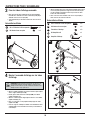
ASSEMBLY INSTRUCTIONS
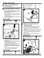
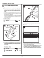
6Attach Height Adjustment Handle
Place the height adjustment handle assembly (C) over the
two holes on the height adjustment bar.
Make sure the handle assembly is oriented on the right
side of the machine.
Pass two M8x40 Hex Bolts (CC) through the bottom of the
height adjustment bar and the two holes on the base
of the handle assembly.
Fasten these bolts with two M8 Nylon Lock Nuts (GG) using
13 mm and 14 mm wrench.
Align the hole at the end of the handle slide arm on the
right side of the Angle Bracket (KK) earlier attached to
the main housing.
Place a Spacer Bushing (LL) between the Angle Bracket
(KK) and the end of the handle slide arm.
Slide a M8x20 Hex Bolt (EE) through the Angle Bracket
(KK), Spacer Bushing (LL) and handle slide arm.
Place a Washer (JJ) over the end of this bolt and fasten
with a M8 Nylon Lock Nut (GG) using 13 mm and 14 mm
wrench.
Ensure everything is aligned correctly and test the
movement on the height adjustment handle.
7Mount the Connecting Rod to the
Sweeper Housing
Remove the right angle connecting rod (G) from the box.
Align it on the back of the unit with a flat end pressed
against the unit and a flat end on top extending in your
direction.
Slide a M6x12 Hex Bolt (II) through the hole in the connecting
rod and into the top hole in the back of the main housing (H).
Loosely fasten with a M6 Nylon Lock Nut (HH) using two
10mm wrenches.
Repeat on the other side of the unit and tighten the nuts.
Hardware Used
Hardware Used
CC x 2M8x40 Hex Bolt
x 2M8 Nylon Lock Nut
GG
x 2M6x12 Hex Bolt
II
x 2M6 Nylon Lock Nut
HH
7
II
5Tighten all nuts and bolts from
Steps 2 thought 4.
II
G
HH
H
CC
GG
C
x 1Ø8 Large Flat Washer
JJ
x 1Spacer Bushing
LL
B
Hardware Used
x 1M8x20 Hex Bolt
EE
x 1M8 Nylon Lock Nut
GG
EE
KK
LL
JJ
GG
Handle Slide Arm
Height Adjustment Bar
Upper hole
HH

9
ASSEMBLY INSTRUCTIONS
A
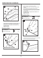
8Assemble Hopper Bag
M
BRACE HOLES ON BOTTOM
INNER BAG LOOPS
Remove the second gold double ended rear hopper tube (M) and
the two support rods (K) from the box.
Place the two support rods (K) in the two holes in the center of
the rear hopper tube (M) already seated in the hopper.
Next take the other rear hopper tube (M) and position it to match
the lower hopper side tube.
Make sure the holes in the center of the bar are facing down.
Step into the bag with the bar. Slide the bar into the top part of the
fabric hopper and insert the two support rods (K) into the holes of
the upper rear hopper tube (M).
HOLE
CAUTION: Do not over-stress (bend) the support rods while
installing. Over stressing causes the rods to bend and lose
supporting tension.
M
M
K
K
C
L
L
M
TT
Hardware Used
TT x 2Plastic Plug
B
Unroll the hopper bag on the ground with the nylon fabric
facing up and the heavy-duty nylon floor facing down.
Remove one of the gold double ended rear hopper tubes
(M) from the box.
Place the rear hopper tube (M) in the back of the hopper
fabric with the holes in the center of the bar facing up.
Remove the gold lower hopper side tubes (L) from the box.
These will be the two L shaped bars with two holes near
one end.
Place the male end of each tube into the female end of the
lower hopper side tube (M) previously placed in the hopper.
Make sure the smaller half of the L shape is facing upwards
as shown in the diagram.
Align the holes on both tube joins and secure by pressing
in a Plastic Plug (TT) into the openings on either side.
Remove the remaining gold upper hopper side tubes (N) from the
box.
Slide these through the fabric sleeves on each side with the
smaller end of the L shape facing the rear of the bag.
Place the male end of each tube into the female end of the upper
rear hopper tube (M) previously placed in the hopper.
Make sure the Larger half of the L shape is facing downwards as
shown in the diagram.
Align the holes on both tube joins and secure by pressing in a
Plastic Plug (TT) into the openings on either side.
Hardware Used
TT x 2Plastic Plug

10
ASSEMBLY INSTRUCTIONS
F
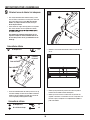
Remove the bag frame strap (J) from the box.
Locate the stitched fabric sleeve at the base of the hopper in
at the front of the canvas.
Insert the bag frame strap (J) into the sleeve.
Pull the base of the hopper fabric up towards the joint of the
upper and lower hopper side tubes and insert Ø6x37 Clevis
Pin (QQ).
Secure the Ø6x37 Clevis Pin (QQ) on the other end with an
Ø2 R Pin (OO).
Repeat on the other side.
Hardware Used
Locate the snap buttons on the nylon fabric. Snap them
into the rivets on the heavy-duty nylon floor of the hopper.
G
QQ
OO
J
L
OO x 2Ø2 R Pin
QQ x 2Ø6x37 Clevis Pin
SNAP
D
Then align the two ends of the upper and lower hopper
side tubes and insert Ø9.5x25 Clevis Pin (PP).
Secure the Ø9.5x25 Clevis Pin (PP) on the other end with
an Ø3 R Pin (NN).
Repeat on the other side.
Hardware Used
NN x 2Ø3 R Pin
L
E
PP x 2Ø9.5x25 Clevis Pin
HEAVY-DUTY NYLON FLOOR OF THE HOPPER
N
NN
PP
TT
N
F
M

11
ASSEMBLY INSTRUCTIONS
9Attach Hopper Bag to Sweeper
Note the orientation of the bag arm tube: vinyl cap upward,
male end facing down and the arm tube (I) on the inside
of the hopper bag (F).
Hardware Used
Tie the rope to the upper hopper tube at the center of the
bag frame.
C
Insert the male ends of the bag arm tubes (I) into the hitch
tubes at the back of the sweeper housing assembly (away
from the hitch). Secure using Ø6X42 clevis pins (RR) and
Ø2 R pin (OO).
NN x 2Ø3 R Pin
Hardware Used
OO x 2Ø2 R Pin
RR x 2Ø6x42 Clevis Pin
BI
RR
OO
Check to see that all bolts are tightened adequately and all pins
are mounted securely. If all the components are securely in
place, the sweeper is completely assembled and ready for use.
There are two holes in the bar of each of the upper hopper
side tubes (N). Locate the top hole and pierce the nylon
fabric at the location of the top hole. Note: some models
have rivets in the fabric and do not require piercing the
fabric.
Check to see that brush protection boards are removed from
inside of sweeper housing assembly.
Insert the front support rod (P) through the top hole in each
of the upper hopper side tubes and assemble bag arm tube
(I). Secure with Ø3 R pin (NN).
ANN
N
F
LOWER HOLE
TOP HOLE
I
VINYL CAP
P

12
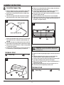
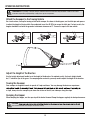
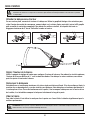
OPERATING INSTRUCTIONS
On a level surface, line up the towing vehicle with sweeper. As shown in the diagram, use the hitch pin and spacers
to adjust the height of the tow hitch. Once adjusted, insert the Ø3 R Pin to secure the hitch pin. For best results, the
hopper should be level with the ground at a minimum clearance of 5”. Secure the rope to the tow vehicle.
Attach the Sweeper to the Towing Vehicle
5” Min
Use the height adjustment handle to set the height of the brushes. For optimal results, the brush height should
be ½” below the tips of the grass. For sweeping other materials, you may need to adjust the height of the brushes.
t
Adjust the Height of the Brushes
Your sweeper is designed to work at speeds of 5 mph and lower. You may damage the device or experience
a slope, always tow the sweeper up or down the surface of the hill, not sideways along the slope.
Towing the Sweeper
When dumping the hopper, use the rope to pull the basket forward. Dump the hopper regularly for best performance.
Dumping the Hopper
WARNING: Before operating or using the sweeper, review the instructions below and safety information. Failure to follow these
instructions may result in property damage or injury to the operator or bystanders.
CAUTION:
excessive heat that will cause damage to the brushes and bag.

13
MAINTENANCE
MAINTENANCE
WARNING: Improper maintenance and storage of the sweeper may void your warranty.
CAUTION: To remove wheel, use a screwdriver to pop off hub cap, remove the lock nut and washer.
After each use clean material out of hopper.
Rinse/dry inside and outside of the sweeper after each use.
Periodically check all fasteners for tightness and replace any damaged fasteners.
Check brushes for debris and keep brushes and brush shaft clean for optimal performance.
Twice a year apply a few drops of light multipurpose oil to the brush shaft bearings.
Annually clean and lightly lubricate all moving parts.
Every two years remove and clean gears and apply an even coat of light synthetic grease.
Use a glossy enamel spray paint to touch up scratched or worn painted metal surfaces.
Never exceed the hopper load capacity rating, it will damage the bag.
Regularly grease axle and wheel bearing area (and apply when needed).
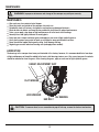
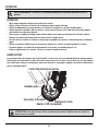
LUBRICATION
The bearings in the sweeper have been pre-lubricated at the factory; however, it is recommended that a few drops
of light multipurpose oil should be added to the brush shaft bearings twice a year. Also, every two years the wheels
should be removed to clean the gears. After cleaning the gears, apply an even coat of light synthetic grease.
HEX BOLT
FLAT WASHER
LOCK WASHER OIL BEARING
HEIGHT ADJUSTMENT SLOT

14
MAINTENANCE
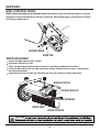
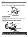
BRUSH REPLACEMENT
CAUTION:
Remove the hopper bag from lawn sweeper.
Only replace one brush at a time.
Tip the sweeper forward on housing. Do not remove the hex bolts from double brush retainers.
Loosen hex bolts and hex lock nuts from single brush retainers. Slide brush out of retainers, making note of
over-lap bristles position.
Install new brush, make sure the over-lap bristles are in the same position as before replacement.
WHEEL GEARS/PAWL SERVICE
DO NOT remove both wheels at the same time. Remove one wheel at a time to prevent mixing parts or using the
wrong parts as the left and right wheels and parts are different. When removing gears, carefully note the position
of all washers and other parts.
DRIVE PIN
RATCHET GEAR
BRUSH ROTATION
BRUSH ROTATION
BRUSH RETAINERS
BRUSH SHAFT
OVERLAP BRISTLES

15
STORAGE AND SPECIFICATIONS
STORAGE
Empty hopper bag before storage as full or partially full bags may pop/explode.
Be sure to completely empty, clean and dry the sweeper hopper bag before storage.
Failure to properly clean the sweeper and hopper may cause deterioration such as rust or mold.
Lightly lubricate all sweeper surfaces and moving parts to protect components and prevent rust.
Store indoors or in a protected area during severe weather and winter months.
Storing the sweeper:
Pull the two bag arm tubes (I) out of hitch tubes (A & B).
Remove the two hopper support rods (K).
Don’t allow the brushes to contact the ground during storage to prevent damage.
SPECIFICATIONS
Frame Construction…………………………………………………………………..Steel
Hopper Construction………………………………………………………...…Nylon Mesh
Hitch Type……………………………………………………………...…………Pin Style
Wheel Type…………………………………………………………….…Semi-Pneumatic
Wheel Size………………….……………………………….……………….……….10.5”

16
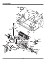
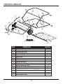
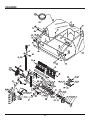
PARTS DRAWING

17
PARTS LIST
ytQ noitpircseD .oN gniwarD #feR
1 ediS thgiR ,ebuT hctiH 3 / N287-000232000-182N 1
1 ediS tfeL ,ebuT hctiH 2 / N287-000222000-182N 2
1 ediS thgiR ,etalp dnE 40001-082N 3
1 ediS tfeL ,etalp dnE 10006-082N 4
1 repparW 3 / N287-000131000-182N 5
2 21×6M ,tloB xeH DXQ-21060-1019 6
6 21×5M ,tloB xeH DX-21050-0119 7
1 doR gnitcennoC D / N287-00003-CDC-30000-182N 8
5 61×8M ,tloB xeH DXQ-61080-1019 9
1 tekcarB elgnA XD-41000-082N 01
1 rehsaW laicepS XD-30001-082N 11
1 yssA ebuT tnemtsujdA thgieH 0 / N287-400000004-182N 21
2 04×8M ,tloB xeH DXQ-04080-1019 31
02 5M ,tuN kcoL nolyN DX-00050-6029 41
2 C rehsaW .jdA HF-34000-082N 51
1 rehsaW talF giB XD-64000-082N 61
1 rehsaW ratS edisnI XD-33000-082N 71
1 reniateR revoC tsuD XD-10001-082N 81
1 gnihsuB tfahS hsurB 20001-082N 91
1 tfahS hsurB X / N287-00027-DXD-72000-182N 02
4 hsurB 0 / N287-310000013-182N 12
61 02×6M,tloB xeH DXQ-02060-1019 22
03 6M,tuN kcoL nolyNDX-00060-6029 32
6 )elbuoD( hsurB ,reniateR XD-10003-082N 42
21 )elgniS( hsurB ,reniateR XD-20003-082N 52
2 E niP sivelC XD-01000-182N 62
2 )evirD( niP lewoD 02060-1049 72
6 5Ø ,rehsaW kcoL gnitnuoM 9316-05000-FH 82
21 8M,tuN kcoL nolyN 9206-08000-DX 92
2 elxA rof recapS XD-53000-082N 03
2 B rehsaW .jdA HF-73000-082N 13
2 gnihsuB XD-82000-082N 23
2 51Ø,gniR gniniateR 9309-15000-FH 33
4 A rehsaW .jdA HF-92000-082N 43
4 01Ø ,rehsaW talF giB9302-10000-DX 53
2 01M,tuN kcoL nolyN 9206-10000-DX 63
2 paC buH 23000-082N 73
2 58×01M,tloB xeH 9101-10085-DX 83
2 5.3×61Ø gnihsuB recapS XD-63000-082N 93

18
PARTS LIST
ytQ noitpircseD .oN gniwarD #feR
1 .H.R raeG noiniP 21000-082N 04
1 .H.L raeG noiniP 03000-082N 14
6 52x5M tloB xeH9101-05025-DXQ 24
2 yssA revoC tsuD 00005-082N 34
2 )raeR( ebuT emarF reppoH D / N287-00006C-60000-182N 44
2 01Ø rehsaW kcoL9306-1000-DX 54
4 gulP citsalP 20000-082N 74
1 gaB reppoH 9 / N287-000393000-182N 84
2 C niP sivelC XD-61000-082N 94
1 partS emarF gaB 5 / N287-000151000-182N 05
2 doR troppuS reppoH82-000092N 15
1 epoR reppoH 83000-082N 25
2 paC lyniV 90000-182N 35
1Handle Slide Arm XD-91000-082N 45
1 tekcarB hctiH 41000-001N 55
1 )thgiartS(tekcarB hctiH 52000-082N 65
1 eldnaH tnemtsujdA thgieH 02000-082N 75
2 ebuT mrA gaB 11000-182N 85
1 doR troppuS tnorF X / N287-00028D-82000-182N 95
2 )gniraeb htiw( .yssA eriT & leehW 00002-182N 06
4 gnihsuB leehW 43000-082N 16
2 57×8M,tloB xeH9101-08075-DX 26
2 8×55M,tloB xeH9101-08055-DX 36
2 ebuT emarF reppoH reppU D / N281-00008C-80000-182N 46
4 54x6M,tloB xeH9101-06045-DXQ 56
1 thgieH gnitsujdA gnihsuB recapS XD-84000-082N 66
1 citsalP ,bonK 00007-082N 76
1 03×8M,tloB egairraC9114-08030-DX 86
1 8Ø,rehsaW talF giB9302-08000-DX 96
1 pirG eldnaH 40000-082N 07
1 rehsaW hteeT lanretxEN280-00044-DX 17
1 niP hctiH XD-30000-120N 27
2 gniraeB gniR-panS XD-62000-082N 37
5 3Ø niP R XD-74000-082N 47
4 2Ø niP R XD-14000-082N 57
2 B niP sivelC XD-01000-082N 67
2 ebuT emarF reppoH rewoL D / N280-00006C-60000-082N 77
1 02x8M tloB xeH9101-08020-DXQ 64
8 61x5M wercSDX-61050-0119 87

WARRANTY
Limited Warranty
YTL International warrants that the product is free from defects in material and workmanship under normal use for
this warranty, YTL International shall, at its exclusive option, either repair or replace the product (lawn sweeper).
YTL International shall have no obligation under the warranty set forth above if the original purchaser or other
person: improperly assembles the product, misuses the product, overloads the product, operates or uses the
product contrarily to instructions, or if the product has been repaired or altered by anyone other than an authorized
representative.
Limited Warranty Exclusions
The limited warranty does not cover cosmetic defects, including, but not limited to, product paint and decals;
nor does it cover items subject to ordinary wear from use of the product, including, but not limited to, tires.
The warranty shall be voided by alteration of the product (except by YTL International), tampering with, improper
installation or maintenance, accident or misuse. This warranty expressly excludes all damage to the product
resulting from careless or neglectful handling or transportation once it has left YTL International’s premises.
The product (lawn sweeper) requires consistent, periodic service for optimal performance and normal maintenance
of the product is expressly excluded from the warranty. The warranty does not cover repair when normal use has
exhausted the life of a part or the equipment as a whole. YTL International also does not warranty consumable
The warranty will not apply to parts and/or labor if the product (lawn sweeper) has been misused, neglected,
Limits of Implied Warranty and Consequential Damage Exclusion
YTL International disclaims any obligation to cover any loss of time, use of this product, freight, or any incidental
or consequential claim by anyone from using this lawn sweeper. This warranty is given in place of all other
for purpose, or merchantability and the vendor accepts no liability, under any circumstances whatsoever, for any
consequential damage or loss suffered by anyone as a result of using or being unable to use the product.
An exchanged/replaced product will be subject to the original limited warranty and warranty coverage will be
calculated from the purchase date of the original product.
may also have other rights you may be entitled to that are not listed within this warranty.
Please contact YTL International directly for warranty related questions and requests.
Contact Information
YTL International
17517 Fabrica Way, Suite H
Cerritos, CA 90703
Phone: (888) 723-6534
Phone: (562) 404-8016
Fax: (562) 404-8013
E-mail: [email protected]
Website: www.ytlinternational.com
19
supply-type items (such as oils/uids, grease, etc.) sold with the product.
warranties and assurances, whether express or implied, including but not limited to, matters of quality, tness

¿Preguntas, problemas, piezas faltantes?
Antes de volver a la tienda, llame a nuestro Departamento
de Servicio al Cliente al 1-888-723-6534, de lunes a viernes de
Número de serie Fecha de compra
2022 Version N281 & N287 [email protected]
BALAYEUSE À FEUILLES ET À
GAZON TRACTABLE DE
121,92 CM (48 PO) / 137,2 CM (54 PO)
ADJUNTE SU RECIBO AQUÍ
20
La page est en cours de chargement...
La page est en cours de chargement...
La page est en cours de chargement...
La page est en cours de chargement...
La page est en cours de chargement...
La page est en cours de chargement...
La page est en cours de chargement...
La page est en cours de chargement...
La page est en cours de chargement...
La page est en cours de chargement...
La page est en cours de chargement...
La page est en cours de chargement...
La page est en cours de chargement...
La page est en cours de chargement...
La page est en cours de chargement...
La page est en cours de chargement...
La page est en cours de chargement...
La page est en cours de chargement...
-
 1
1
-
 2
2
-
 3
3
-
 4
4
-
 5
5
-
 6
6
-
 7
7
-
 8
8
-
 9
9
-
 10
10
-
 11
11
-
 12
12
-
 13
13
-
 14
14
-
 15
15
-
 16
16
-
 17
17
-
 18
18
-
 19
19
-
 20
20
-
 21
21
-
 22
22
-
 23
23
-
 24
24
-
 25
25
-
 26
26
-
 27
27
-
 28
28
-
 29
29
-
 30
30
-
 31
31
-
 32
32
-
 33
33
-
 34
34
-
 35
35
-
 36
36
-
 37
37
-
 38
38


Red Rock 8469538 Le manuel du propriétaire
- Taper
- Le manuel du propriétaire
dans d''autres langues
- English: Red Rock 8469538 Owner's manual
Autres documents
-
Agri-Fab 45-05221 Le manuel du propriétaire
-
-
-
-
-
-
-
-
Husqvarna SWEEPER 960 Le manuel du propriétaire
-
GYS ABB IRB 2600ID Manuel utilisateur