Honeywell Digital Line Volt Non-Programmable Thermostat Manuel utilisateur
- Catégorie
- Thermostats
- Taper
- Manuel utilisateur
Ce manuel convient également à

USER GUIDE
33-00209EF-05
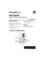
RLV3150
ELECTRONIC THERMOSTAT
APPLICATION
This thermostat is designed to control
an electric heating system such as a
baseboard heater, a convector or a fan-
forced heater.
The thermostat cannot be used with the
following:
• a resistive load under 2 A
• a resistive load over 12.5 A
• systems driven by a contactor or a
relay (inductive load)
• central heating systems
Supplied Parts
• One (1) thermostat
• Two (2) 6-32 mounting screws
• Two (2) solderless connectors
CONTROLS AND DISPLAY
Fig. 1.
Backlit Screen
Up button
Temperature
Heating intensity
indicator (the image
disappears when
heating is off)
Appears when the
setpoint is displayed
Appears when the
thermostat is configured
for a fan-forced heater
(see page 3)
The settings are locked
Down button

RLV3150
33-00209EF—05 2
INSTALLATION
GUIDELINES
WARNING
TURN OFF POWER TO THE
HEATING SYSTEM AT THE
MAIN POWER PANEL TO
AVOID ELECTRICAL SHOCK.
• The installation must comply with
local electrical codes.
• Do NOT install the thermostat in an
area where it can be exposed to water
or rain.
• Avoid locations where there are air
drafts (such as the top of a staircase
or an air outlet), dead air spots (such
as behind a door), or direct sunlight.
• Do not install the thermostat on a
wall section that conceals air ducts,
chimney pipes or stove pipes.
• Install the thermostat about 1.5 m
(5 feet) high, on an inside wall facing
the heater.
• Install the thermostat onto an
electrical box.
• This thermostat has tinned copper
wires for line and load connections.
Special CO/ALR solderless
connectors must be used if the
thermostat will be connected to
aluminum wires.
• The thermostat wires are not
polarized; either wire can be
connected to the load or to the power
supply.
• Keep the air vents at the top and
bottom of the thermostat clean and
free from obstructions.
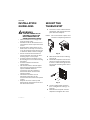
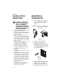
MOUNT THE
THERMOSTAT
1. Loosen the screw underneath the
thermostat and separate the face-
plate from the wallplate.
NOTE: The screw remains captive and
cannot be completely removed.
Fig. 2.
2. Wire the thermostat (see “Wiring”
on page 3).
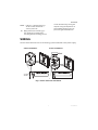
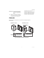
3. Mount the wallplate to the electri-
cal box using the provided screws.
Insert the screws through the two
left or right mounting holes of the
wallplate.
Fig. 3.
4. Set the configuration switches
(see “Configuration Settings” on
page 4).
5. Reinstall the faceplate onto the
wallplate and tighten the screw.

RLV3150
3 33-00209EF—05
NOTE: If there is a protective film or
sticker on the thermostat’s
screen, peel it off.
6. Apply power to the heating sys-
tem. Verify the installation by
checking that the heating system
can be turned On by raising the
setpoint using the Up button or
turned Off by lowering the set-
point using the Down button.
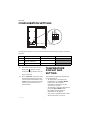
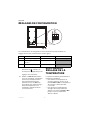
WIRING
Connect the thermostat wires to the heating system (load) and to the power supply.
Fig. 4. 2-wire and 4-wire installation.
2-wire Installation 4-wire Installation

RLV3150
33-00209EF—05 4
CONFIGURATION SETTINGS
Fig. 5.
Configuration switches are on the back of the faceplate. Factory settings are inside
gray cells.
1. The thermostat buttons are dis-
abled and appears on the
screen (see page 1) when the set-
tings are locked.
2. Place at Fan Yes if you have a fan-
forced heater (to prevent prema-
ture burnout of the motor). Leave
at No for better temperature regu-
lation if you do not have a fan-
forced heater.
TEMPERATURE
DISPLAY AND
SETTING
The thermostat generally displays the
room temperature.
• To display the set temperature
(setpoint), press the Up or Down
button once. The setpoint
temperature will remain on the
screen for 5 seconds.
• To change the setpoint temperature,
press the Up or Down button
repeatedly until the desired
temperature is displayed.
• The screen is backlit for 10 seconds
when any button is pressed.
# Parameter Up Down
1Settings lock 1Lock Unlock
2Fan-forced heater 2Fan Yes No
3Unit °F °C

RLV3150
5 33-00209EF—05
SETUP MENU
1. Press the Up and Down buttons
simultaneously for three seconds
to enter the setup menu.
2. Press the Up or Down button to
change the option.
3. Press the Up and Down buttons
simultaneously and briefly to
advance to the next parameter.
4. When the last parameter is dis-
played, press the Up and Down
buttons for three seconds to save
any changes and exit the menu.
NOTE: If you do not press any button
for 15 seconds, the thermostat
will automatically save any
changes you have made and
will then return to its normal
display.
IN CASE OF DIFFICULTY
Parameter Options
Display and
default setting
Minimum setpoint 5°C - 30°C (41°F - 86°F)
NOTE: The minimum setpoint cannot be
set higher than the value set for
the maximum setpoint.
Maximum setpoint 5°C - 30°C (41°F - 86°F)
NOTE: The maximum setpoint cannot be
set lower than the value set for the
minimum setpoint.
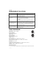
PROBLEM SOLUTIONS
Thermostat is hot. This is normal unless the thermostat is too hot to touch. Ensure that the heater
capacity does not exceed the thermostat’s maximum load.
Wrong temperature is
displayed.
Avoid any of the following conditions:
The thermostat is exposed to an air draft.
The thermostat is located near or above a heat source such as a light dimmer.
Display disappears and
reappears after a few
minutes.
The thermal circuit breaker on the heater has temporarily opened. This can happen
if the heater is obstructed by furniture or curtain and has overheated, or if the
thermal circuit breaker is defective or too sensitive.
Display looks faded when
heating is activated.
The heater capacity is probably less than the thermostat minimum load
requirement. The thermostat cannot be used below that rating.

RLV3150
33-00209EF—05 6
SPECIFICATIONS
Supply: 240 VAC, 60 Hz
Minimum load: 2A (resistive only) 500W @ 240VAC
Maximum load: 12.5 A (resistive only) 3000 W @ 240 VAC
Display range: 0°C to 50.0°C (32°F to 122°F)
Setpoint range: 5.0°C to 30.0°C (41°F to 86°F)
Resolution: 0.5°C (1°F)
Operating temperature: 0°C to 50.0°C (32°F to 122°F)
Storage: -20.0°C to 50.0°C (-4°F to 122°F)
Permanent Memory: You do not need to adjust the temperature or thermostat
configurations following a power outage.
1-YEAR LIMITED WARRANTY
Resideo warrants this product, excluding battery, to be free from defects in workmanship or materials, under
normal use and service, for a period of one (1) year from the date of first purchase by the original purchaser. If
at any time during the warranty period the product is determined to be defective due to workmanship or
materials, Resideo shall repair or replace it (at Resideo’s option).
If the product is defective,
(i) return it, with a bill of sale or other dated proof of purchase, to the place from which you purchased it; or
(ii) call Resideo Customer Care at 1-800-468-1502. Customer Care will make the determination whether the
product should be returned to the following address: Resideo Return Goods, 1985 Douglas Dr. N., Golden
Valley, MN 55422, or whether a replacement product can be sent to you.
This warranty does not cover removal or reinstallation costs. This warranty shall not apply if it is shown by
Resideo that the defect was caused by damage which occurred while the product was in the possession of a
consumer.
Resideo’s sole responsibility shall be to repair or replace the product within the terms stated above. RESIDEO
SHALL NOT BE LIABLE FOR ANY LOSS OR DAMAGE OF ANY KIND, INCLUDING ANY INCIDENTAL OR
CONSEQUENTIAL DAMAGES RESULTING, DIRECTLY OR INDIRECTLY, FROM ANY BREACH OF ANY
WARRANTY, EXPRESS OR IMPLIED, OR ANY OTHER FAILURE OF THIS PRODUCT.
Some states do not allow the exclusion or limitation of incidental or consequential damages, so this
limitation may not apply to you.
THIS WARRANTY IS THE ONLY EXPRESS WARRANTY RESIDEO MAKES ON THIS PRODUCT. THE DURATION
OF ANY IMPLIED WARRANTIES, INCLUDING THE WARRANTIES OF MERCHANTABILITY AND FITNESS FOR
A PARTICULAR PURPOSE, IS HEREBY LIMITED TO THE ONE YEAR DURATION OF THIS WARRANTY. Some
states do not allow limitations on how long an implied warranty lasts, so the above limitation may not apply
to you.
This warranty gives you specific legal rights, and you may have other rights which vary from state to state. If
you have any questions concerning this warranty, please write Resideo Customer Care, 1985 Douglas Dr,
Golden Valley, MN 55422 or call 1-800-468-1502.
273699
Energy Verified
Only

RLV3150
7 33-00209EF—05
CUSTOMER ASSISTANCE
If you have any questions about the product installation or operation, or concerning
the warranty, contact us at:
Resideo
1985 Douglas Drive North
Golden Valley, MN 55422
USA
1-800-468-1502
For more information on our products, go to: honeywellhome.com
CAUTION: ELECTRONIC WASTE NOTICE
The product should not be disposed of with other household waste. Check for the
nearest authorized collection centers or authorized recyclers. The correct disposal of
end-of-life equipment will help prevent negative consequences for the environment
and human health.
ICES-003 CLASS B NOTICE
This Class B digital apparatus complies with Canadian ICES-003.
FCC statement available at https://customer.resideo.com/en-US/support/
residential/codes-and-standards/FCC15105/Pages/default.aspx

RLV3150
© 2021 Resideo Technologies, Inc. All rights reserved.
The Honeywell Home trademark is used under license from Honeywell International, Inc. This product is manufactured by Resideo Technologies, Inc. and its affiliates.
Tous droits réservés. La marque de commerce Honeywell Home est utilisée avec l’autorisation d’Honeywell International, Inc.
Ce produit est fabriqué par Resideo Technologies, Inc. et ses sociétés affiliées.
www.resideo.com
Resideo Technologies, Inc.
1985 Douglas Drive North, Golden Valley, MN 55422
1-800-468-1502
33-00209EF—05 M.S. Rev. 01-21 | Printed in United States

GUIDE DE L’UTILISATEUR
RLV3150
THERMOSTAT ÉLECTRONIQUE
APPLICATION
Ce thermostat est conçu pour réguler
un système de chauffage électrique tel
qu'un chauffage de plinthe, un
convecteur ou un chauffage à
ventilation forcée.
Le thermostat ne peut pas être utilisé
dans les cas suivants :
• charge résistive inférieure à 2 A
• charge résistive supérieure à 12,5 A
• systèmes entraînés par un
contacteur ou un relais (charge
inductive)
• systèmes de chauffage central
Pièces fournies
• Un (1) thermostat
• Deux (2) vis de montage 6-32
• Deux (2) connecteurs sans soudure
COMMANDES ET AFFICHAGE
Fig. 6.
Écran rétroéclairé
Bouton haut
Indicateur de l'intensité
de chauffage (l'image
disparaît lorsque le
chauffage est éteint)
S’affiche lorsque le
point de consigne
est affiché
S'affiche lorsque le
thermostat est configuré
pour un chauffage à
ventilation forcée
(voir page 9)
Les paramètres
sont verrouillés
Bouton bas
Température

RLV3150
33-00209EF—05 10
INSTALLATION
DIRECTIVES
AVERTISSEMENT
COUPER L'ALIMENTATION
VERS LE SYSTÈME DE
CHAUFFAGE AU NIVEAU DU
PANNEAU D'ALIMENTATION
PRINCIPAL POUR ÉVITER LES
CHOCS ÉLECTRIQUES.
• L'installation doit être conforme aux
codes d'électricité locaux.
• NE PAS installer le thermostat dans
une zone où il pourrait être exposé à
de l'eau ou la pluie.
• Éviter les endroits où il y a des
courants d'air (tels que le haut d'un
escalier ou une sortie d'air), les zones
mortes (comme derrière une porte)
ou les endroits exposés à la lumière
directe du soleil.
• Ne pas installer le thermostat sur un
pan de mur qui dissimule des
conduites d'air, des tuyaux de
cheminée ou tuyaux de poêle.
• Installer le thermostat à environ
1,5 m (5 pieds) de haut, sur un mur
intérieur face à l'appareil de
chauffage.
• Installer le thermostat sur un boîtier
électrique.
• Ce thermostat a des fils de cuivre
étamé pour les connexions de ligne
et de charge. Des connecteurs sans
soudure CO/ALR spéciaux doivent
être utilisés si le thermostat sera
connecté avec des fils en aluminium.
• Les fils du thermostat ne sont pas
polarisés; l'un ou l'autre fil peut être
raccordé à la charge ou à
l'alimentation.
• Maintenir les évents en haut et en
bas du thermostat propres et
exempts d'obstructions.
MONTER LE
THERMOSTAT
1. Desserrer la vis qui se trouve des-
sous le thermostat et séparer la
plaque frontale de la plaque
murale.
REMARQUE : La vis reste captive et ne
peut pas être complète-
ment retirée.
Fig. 7.
2. Câbler le thermostat (voir «
Câblage » à la page 11).
3. Monter la plaque murale sur le
boîtier électrique en utilisant les
vis fournies. Insérer les vis par les
trous de montage gauche ou droit
de la plaque murale.
Fig. 8.
4. Régler les commutateurs de con-
figuration (voir « Réglages de
configuration » à la page 12).
5. Réinstaller la plaque frontale sur
la plaque murale et serrer la vis.

RLV3150
11 33-00209EF—05
REMARQUE : Si l'écran du thermostat
comporte un film protec-
teur ou un autocollant, le
retirer.
6. Mettre le système de chauffage
sous tension. Vérifier l'installation
en vérifiant que le système de
chauffage peut être mis en
marche en augmentant le point de
consigne à l'aide du bouton Haut
ou éteint en réduisant le point de
consigne à l'aide du bouton Bas.
CÂBLAGE
Connecter les fils du thermostat au système de chauffage (charge) et à
l'alimentation.
Fig. 9. Installation à deux fils et à quatre fils.
Installation à 2 fils Installation à 4 fils

RLV3150
33-00209EF—05 12
RÉGLAGES DE CONFIGURATION
Fig. 10.
Les commutateurs de configuration sont à l'arrière de la plaque frontale. Les
réglages d'usine sont à l'intérieur des cellules grises.
1. Les boutons du thermostat sont
désactivés et s'affiche sur
l'écran (voir la page 9) lorsque les
réglages sont verrouillés.
2. Mettre sur Fan Yes (ventilateur
oui) si un chauffage à ventilation
forcée est présent (pour éviter
l'épuisement prématuré du
moteur). Laisser sur No (non)
pour obtenir une meilleure régu-
lation de température si un
chauffage à ventilation forcée
n'est pas présent.
AFFICHAGE ET
RÉGLAGE DE LA
TEMPÉRATURE
Le thermostat affiche généralement la
température ambiante.
• Pour afficher la température de
consigne, appuyer une fois sur le
bouton Haut ou Bas. La température
de consigne s'affiche pendant
5secondes.
• Pour ignorer la température de
consigne de façon permanente,
appuyer sur le bouton Haut ou Bas
jusqu'à ce que la température
désirée s'affiche.
N° Paramètre Haut Bas
1Verrouillage réglages 1Verrouillage Déverrouillage
2 Chauffage à ventilation
forcée 2
Ventilateur Oui Non
3Unité °F °C

RLV3150
13 33-00209EF—05
• L'écran est rétroéclairé pendant 10
secondes lorsqu'un bouton
quelconque est pressé.
MENU DE
CONFIGURATION
1. Appuyer simultanément sur les
boutons Haut et Bas pendant
trois secondes pour entrer dans le
menu de configuration.
2. Appuyer sur le bouton Haut ou
Bas pour modifier l'option.
3. Appuyer simultanément sur les
boutons Haut et Bas brièvement
pour passer au paramètre suivant.
4. Lorsque le dernier paramètre est
affiché, appuyer simultanément
sur les boutons Haut et Bas pen-
dant trois secondes pour enregis-
trer toute modification et quitter le
menu.
REMARQUE : Si aucun bouton n'est
pressé pendant
15 secondes, le thermo-
stat enregistre automa-
tiquement toutes les
modifications effectuées
et retourne ensuite à son
affichage normal.
Paramètre Options
Affichage et
réglage par
défaut
Point de consigne
minimum 5 °C - 30 °C (41 °F - 86 °F)
REMARQUE : Le point de consigne mini-
mum ne peut pas être défini à
une valeur supérieure à celle
du point de consigne maxi-
mum.
Point de consigne
maximum 5 °C - 30 °C (41 °F - 86 °F)
REMARQUE : Le point de consigne maxi-
mum ne peut pas être défini à
une valeur inférieure à celle
du point de consigne mini-
mum.

RLV3150
33-00209EF—05 14
PROBLÈMES ET SOLUTIONS
FICHE TECHNIQUE
Alimentation : 240 V c.a., 60 Hz
Charge minimum :
2 A (résistive seulement)
500 W à 240 V c.a.
Charge maximale :
12,5 A (résistive seulement)
3000 W à 240 V c.a.
Plage d'affichage : 0°C à 50,0°C (32°F à 122°F)
Plage de point de consigne : 5,0°C à 30,0°C (41°F à 86°F)
Résolution : 0,5 °C (1 °F)
Température de fonctionnement : 0°C à 50,0°C (32°F à 122°F)
Stockage : -20,0°C à 50,0°C (-4°F à 122°F)
Mémoire permanente :
Il est inutile de régler la température ou le thermostat après une panne de courant.
Problèmes Solutions
Le thermostat est chaud. Ceci est normal. En fonctionnement normal, le boîtier du
thermostat peut atteindre une température entre 35 °C
(95 °F) et 40 °C (104 °F).
La température affichée
est erronée. Corriger si l’une des conditions suivantes existe :
• Il y a un courant d’air à proximité.
• L’autocollant sur l’écran du thermostat n’a pas été
enlevé.
• Le thermostat est situé près ou au-dessus d’une
source de chaleur tel qu’un gradateur de lumière.
L’affichage disparaît et
ne réapparaît qu’après
quelques minutes.
La protection thermique de la plinthe était
temporairement ouverte. Ceci peut se produire suite à
une surchauffe lorsque la plinthe est obstruée par un
meuble ou un rideau, ou si la protection thermique de la
plinthe est trop sensible.
L’affichage est pâle
lorsque le chauffage est
activé.
Le système de chauffage est inférieur à la charge
minimale requise. Dans le cas échéant, ce thermostat ne
peut pas être utilisé.
273699
Energy Verified
Only

RLV3150
15 33-00209EF—05
GARANTIE LIMITÉE D'UN AN
Resideo garantit ce produit, à l’exception des piles, contre tout défaut de pièce ou de
main-d’oeuvre, durant une période pour un (1) an à partir de la date d’achat par le
consommateur d’origine si le produit est utilisé et entretenu convenablement. En cas
de défaillance ou de mauvais fonctionnement pendant la période de garantie,
Resideo remplacera ou réparera le produit, à sa discrétion.
Si le produit est défectueux
(i) renvoyez-le avec la facture ou une autre preuve d’achat date au lieu d’achat; ou
(ii) appelez le service à la clientèle de Resideo en composant le 1-800-468-1502. Le
service à la clientèle déterminera si le produit doit être retourné à l’adresse suivante :
Resideo Return Goods, 1985 Douglas Dr. N., Golden Valley, MN 55422, ou si un
produit de remplacement peut vous être expédié.
La présente garantie ne couvre pas les frais de retrait ou de réinstallation. La
présente garantie ne s’applique pas s’il est démontré par Resideo que la défaillance
ou le mauvais fonctionnement sont dus à un endommagement du produit alors que
le consommateur l’avait en sa possession.
La responsabilité exclusive de Resideo se limite à réparer ou à remplacer le produit
conformément aux modalités susmentionnées. RESIDEO N’EST EN AUCUN CAS
RESPONSABLE DES PERTES OU DOMMAGES, Y COMPRIS LES DOMMAGES
INDIRECTS OU ACCESSOIRES DÉCOULANT DIRECTEMENT OU INDIRECTEMENT
D’UNE VIOLATION QUELCONQUE D’UNE GARANTIE, EXPRESSE OU TACITE,
APPLICABLE AU PRÉSENT PRODUIT, OU TOUTE AUTRE DÉFAILLANCE DU
PRÉSENT PRODUIT. Certaines provinces ne permettent pas l’exclusion ou la
restriction des dommages indirects ou accessoires et, par conséquent, la présente
restriction peut ne pas s’appliquer.
CETTE GARANTIE EST LA SEULE GARANTIE EXPRESSE FAITE PAR RESIDEO POUR
CE PRODUIT. LA DURÉE DE TOUTE GARANTIE IMPLICITE, INCLUANT LES
GARANTIES DE QUALITÉ MARCHANDE OU D’ADAPTATION À UNE UTILISATION
PARTICULIÈRE, EST LIMITÉE PAR LES PRÉSENTES À LA PÉRIODE DE UN AN DE LA
PRÉSENTE GARANTIE. Certaines provinces ne permettent pas de limiter la durée
des garanties tacites et, par conséquent, la présente limitation peut ne pas
s’appliquer.
La présente garantie donne au consommateur des droits spécifiques et certains
autres droits qui peuvent varier d’une province à l’autre.
Pour toute question concernant la présente garantie, prière d’écrire aux Services à la
clientèle de Resideo à l’adresse suivante : Resideo Customer Relations, 1985
Douglas Dr, Golden Valley, MN 55422 ou composer le 1-800-468-1502.

RLV3150
© 2021 Resideo Technologies, Inc. All rights reserved.
The Honeywell Home trademark is used under license from Honeywell International, Inc. This product is manufactured by Resideo Technologies, Inc. and its affiliates.
Tous droits réservés. La marque de commerce Honeywell Home est utilisée avec l’autorisation d’Honeywell International, Inc.
Ce produit est fabriqué par Resideo Technologies, Inc. et ses sociétés affiliées.
www.resideo.com
Resideo Technologies, Inc.
1985 Douglas Drive North, Golden Valley, MN 55422
1-800-468-1502
33-00209EF—05 M.S. Rev. 01-21 | Imprimé aux États-Unis
SERVICE À LA CLIENTÈLE
Si vous avez des questions sur le fonctionnement de votre thermostat ou concernant
la présente garantie, prière de nous joindre à :
Resideo
1985 Douglas Drive North
Golden Valley, MN 55422
USA
1-800-468-1502
Pour de plus amples informations sur nos produits, visiter :
honeywellhome.com
MISE EN GARDE : AVIS DE DÉCHETS ÉLECTRONIQUES
Ne disposez pas ce produit avec les autres ordures ménagères. Recherchez les
centres de collecte ou de recyclage accrédités les plus proches. La mise au rebut
appropriée de l’équipement en fin de vie aidera à prévenir tout effet potentiellement
nuisible à l’environnement et à la santé humaine.
AVIS ICES-003 DE CLASSE B
Cet appareil numérique de la classe B est conforme à la norme NMB-3 du Canada.
Déclaration de la FCC sur : https://customer.resideo.com/en-US/support/
residential/codes-and-standards/FCC15105/Pages/default.aspx
-
 1
1
-
 2
2
-
 3
3
-
 4
4
-
 5
5
-
 6
6
-
 7
7
-
 8
8
-
 9
9
-
 10
10
-
 11
11
-
 12
12
-
 13
13
-
 14
14
-
 15
15
-
 16
16


Honeywell Digital Line Volt Non-Programmable Thermostat Manuel utilisateur
- Catégorie
- Thermostats
- Taper
- Manuel utilisateur
- Ce manuel convient également à
dans d''autres langues
Documents connexes
Autres documents
-
 Honeywell Home RLV4305A1000/U1 Le manuel du propriétaire
-
resideo TH305/H Mode d'emploi
-
Honeywell Home RLV3120 Le manuel du propriétaire
-
-
-
-
-
resideo TH209/U Mode d'emploi
-
