GE GFT14ESSLWW Le manuel du propriétaire
- Catégorie
- Sèche-linge
- Taper
- Le manuel du propriétaire
Ce manuel convient également à

GE is a trademark of the General Electric Company. Manufactured under trademark license.
0020507767Z 49-90571-3 10-19 GEA
DRYERS
SAFETY INFORMATION ..........3
USING THE DRYER
Getting Started ...................... 4
Loading ..............................8
Features ..............................8
CARE AND CLEANING ...........9
INSTALLATION
INSTRUCTIONS .....................12
Stacking (Optional) .....................20
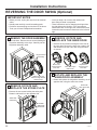
Reversing The Door Swing (Optional). . . . . 22
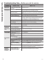
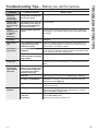
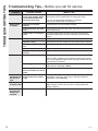
TROUBLESHOOTING TIPS ..... 24
LIMITED WARRANTY ...........27
CONSUMER SUPPORT ..........28
GFT14
OWNER’S MANUAL &
INSTALLATION
INSTRUCTIONS
Write the model and serial
numbers here:
Model # _________________
Serial # _________________
They are on the label on the front
of the dryer behind the door.
ENGLISH/FRANÇAIS/
ESPAÑOL

2 49-90571-3
THANK YOU FOR MAKING GE APPLIANCES A PART OF YOUR HOME.
Whether you grew up with GE Appliances, or this is your first, we’re happy to have you in the family.
We take pride in the craftsmanship, innovation and design that goes into every GE Appliances
product, and we think you will too. Among other things, registration of your appliance ensures that we
can deliver important product information and warranty details when you need them.
Register your GE appliance now online. Helpful websites and phone numbers are available in the
Consumer Support section of this Owner’s Manual. You may also mail in the pre-printed registration
card included in the packing material.

49-90571-3 3
READ AND SAVE THESE INSTRUCTIONS
IMPORTANT SAFETY INFORMATION
READ ALL INSTRUCTIONS BEFORE USING THE APPLIANCE
To reduce the risk of fire, explosion, electric shock, or injury to persons when using your appliance,
follow basic precautions, including the following:
Ŷ
Read all instructions before using the appliance.
Ŷ
DO NOT dry articles that have been previously cleaned in, washed in, soaked in, or spotted with gasoline,
dry-cleaning solvents, or other flammable or explosive substances, as they give off vapors that could ignite or
explode.
Ŷ
DO NOT place items exposed to cooking oils in your dryer. Items contaminated with cooking oils may contribute to a
chemical reaction that could cause a load to catch fire. To reduce the risk of fire due to contaminated loads, the final
part of the tumble dryer cycle occurs without heat (cool down period). Avoid stopping a tumble dryer before the end
of the drying cycle unless all items are quickly removed and spread out so that the heat is dissipated.
Ŷ
DO NOT allow children to play on or in this appliance. Close supervision of children is necessary when this
appliance is used near children.
Ŷ
Before the appliance is removed from service or discarded, remove the door to the drying compartment.
Ŷ
DO NOT reach into the appliance if the drum is moving.
Ŷ
DO NOT install or store this appliance where it will be exposed to the weather.
Ŷ
DO NOT tamper with controls.
Ŷ
DO NOT climb or stand on this unit.
Ŷ
DO NOT repair or replace any part of this appliance or attempt any servicing unless specifically recommended
in the user-maintenance instructions or in published user-repair instructions that you understand and have the
skills to carry out.
Ŷ
Follow all fabric care instructions and warnings to prevent melting of garments or damage to the appliance.
Ŷ
DO NOT use fabric softeners or products to eliminate static unless recommended by the manufacturer of the
fabric softener or product.
Ŷ
DO NOT dry articles containing foam rubber or similarly textured rubber-like materials.
Ŷ
Clean lint screen and clean and empty the condenser before or after each load.
Ŷ
DO NOT operate the dryer without the lint filter and condenser in place.
Ŷ
D O N O T store combustible materials, gasoline or other flammable liquids near the dryer. Keep area around the air
intake vent on the front of the dryer and adjacent surrounding areas free from the accumulation of lint, dust and dirt.
Ŷ
The interior of the appliance should be cleaned periodically by qualified service personnel.
Ŷ
Unplug the appliance or turn off the circuit breaker before servicing. Pressing the Power or Start/Pause button DOES
NOT disconnect power.
Ŷ
DO NOT operate this appliance if it is damaged, malfunctioning, partially disassembled, or has missing or
broken parts, including a damaged cord or plug.
Ŷ
DO NOT spray any type of aerosol into, on or near dryer at any time. DO NOT use any type of spray cleaner when
cleaning dryer interior. Hazardous fumes or electrical shock could occur
.
Ŷ
See “ELECTRICAL CONNECTION” located in the Installation Instructions for grounding instructions.
WARNING
SAFETY INFORMATION

4 49-90571-3
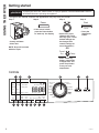
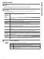
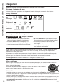
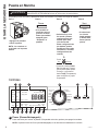
Getting started
USING THE DRYER
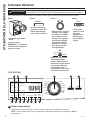
Throughout this manual, features and appearance may vary from your model.
Controls
• If the screen is dark,
press the Power button
to “wake up” the display.
Step 2 Step 3
Step 4
Step 1
• Select a dry cycle.
(Defaults are set for
each dry cycle. These
default settings can
be changed. See
control settings for
more information.)
OR
• Press the
Start/Pause
button.
• Loosely add items.
• Close door.
NOTE: Dryer will not start
with door open.
To reduce the risk of fire, electric shock, or injury to persons, read the IMPORTANT SAFETY
INFORMATION before operating this appliance.
WARNING
Power
• Press Timed Dry
button, rotate knob
to adjust time, and
press Temp button
to set your own
temperature.
Start
Pause
Temp
Timed
Dry
Damp DelayDamp
Dry
Ex Dry
Damp Timed
Clean Filter
No Heat
Low
High
Medium
DRY DAMP COOL
Est Time Remaining
Tumble
My Cycle
Power
Start
Pause
Warm Up
Rack Dry
Quick Dry
Delicates
Cottons
Heavy
Duty
Active
Wear
Casuals
To w e l s
Sanitize
Dewrinkle
Empty Tank
Mixed Loads
Timed
Dry
Damp
Alert
Level
Ext
Tumble
My Cycle
Temp eDry
Hold to Set
Delay
Dry
C
L AKBM
D E F H I J
N
G

49-90571-3 5
USING THE DRYER
Getting started
B
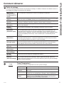
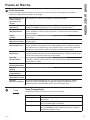
Dry Cycles
The dry cycle controls the cycle time for the drying process. The chart below will help you match
the dry setting with the loads.
Mixed Loads
or Normal
(Depending on
model)
For loads consisting of cottons and poly blends.
Cottons For cottons and most linens. NOTE: Energy Star
®
models are tested on Cottons with
default settings.
Heavy Duty For large coats, bed spreads, mattress covers, sleeping bags, blankets, comforters, jackets,
small rugs, and similar large and bulky items.
Towels Use for towels OR sheets. It is not recommended to mix towels and sheets in the same load.
Casuals For wrinkle-free, permanent press and delicate items, and knits.
Active Wear Clothing worn for active sports exercise and some casual wear. Fabrics include new technology
finishes and stretch fibers such as Spandex. Also for clothing labeled Easy Care or Perma Press:
For wrinkle-free and permanent press items.
Sanitize Reduces certain types of bacteria by 99.6%, including: Staphylococcus aureus and Pseudomonas
aeruginosa. The antibacterial process occurs when high heat is used during a portion of this
drying cycle.
Quick Dry For small loads that are needed in a hurry, such as sports or school uniforms. Can also be
used if the previous cycle left some items damp, such as collars or waistbands.
Delicates For lingerie and special-care fabrics.
Dewrinkle For removing wrinkles from items that are dry or slightly damp. This cycle is not recommended
for delicate fabrics.
Warm Up Provides 25 minutes of warming time to warm up clothes.
Air Fluff Provides 30 minutes of tumbling time without heat.
Rack Dry For drying delicate items without tumbling, use drying rack accessory. Place items flat on the
drying rack such as wool sweaters and delicate fabrics. Dry with low heat.
A
Power
Press to “wake up” the display. If the display is active, press to turn the dryer off.
NOTE: Pressing Power does not disconnect the appliance from the power supply.
C
Temp (Temperature)
You can change the temperature of your dry cycle.
Temp
High For regular to heavy cottons.
Medium For synthetics, blends and items labeled Permanent Press.
Low For delicates, synthetics and items labeled Tumble Dry Low.
No Heat This option may only be used with Air Fluff and Timed Dry, in which items are
tumbled without heat.

6 49-90571-3
Getting started
USING THE DRYER
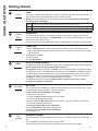
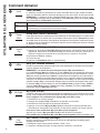
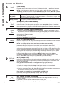
Extended Tumble
Minimizes wrinkles by adding approximately 2 hours of no-heat tumbling after clothes are
dry.
The estimated time remaining display will show “END”.
The extended tumble time does not get added to the cycle time on the display.
I
D
Level
The sensor continuously monitors the amount of moisture in the load. When the moisture in
your clothes reaches your selected dry level, the dryer will stop.
NOTE: Sensor dry Level can be used with all cycles except Timed Dry, Air Fluff, Rack
Dry, Warm Up and Dewrinkle.
E
Damp Alert
This option causes the dryer to beep when clothes have dried to a damp level. Remove
items that you wish to hang dry. The Damp Alert will only beep when this option is selected,
and the dryer will continue to dry.
Removing clothes and hanging them when they are damp can reduce the need to iron some items.
Damp
Alert
F
Timed Dry
1. Press Timed Dry button. Lights around the knob will flash. Select the drying time by
rotating the knob to increase or decrease the time in 10-minute increments up to 2 hours
and 30 minutes.
2. Select the dry Temp.
3. Close the door.
4. Press Start/Pause.
H
My Cycle
Set up your favorite combination of settings and save them here for one touch recall. These
custom settings can be set while a cycle is in progress.
To store a My Cycle combination of settings:
1. Select your drying cycle.
2.
Change Temp and Level settings to fit your needs.
3. Select any drying options you want.
4. Press and hold the My Cycle button for 3 seconds to store your selection. A beep will
sound and the button will light up.
To recall your stored My Cycle combination:
Press the MY CYCLE button before drying a load.
To change your stored My Cycle combination:
Repeat steps 1–4.
My Cycle
Hold to Set
Level
Ex Dry Use for heavy-duty fabrics or items that should be very dry, such as towels.
Dry Use for normal dryness level suitable for most loads. This is the preferred cycle for energy saving.
Damp For leaving items partially damp.
Timed
Dry
Tumble
Ext
G
eDry (on some models)
Reduces total energy consumption of specific dryer cycles by adjusting certain heat settings.
NOTE: Cycle times will change when eDry is selected.
Energy Star
®
models are tested on Cottons cycle with default settings to determine energy
use rating of this dryer. The eDry option will default to on for Cottons. Temperature settings
on High and dryness level setting on Dry are specifically designed for this cycle to reduce
energy consumption. For optimal energy savings, turn eDry on. For optimal drying times,
turn eDry off. Energy savings will vary across loads and cycles.
The eDry selection can be used with Mixed Loads, Cottons, Heavy Duty, Towels,
Casuals, Active Wear and Delicates.
eDry

49-90571-3 7
USING THE DRYER
Getting started
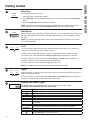
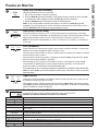
J
Delay Dry
Use to delay the start of your dryer.
1. Choose your dry cycle and any options.
2. Press Delay Dry. You can change the delay time in 1 hour increments, using the Delay Dry
button.
3. Press the Start/Pause button to start the countdown.
NOTE: If the door is opened while the dryer is in Delay Dry, the countdown time will not
restart unless the door is closed and Start/Pause button has been pressed again.
K
Start/Pause
Press to start a cycle. If the dryer is running, pressing it once will pause the dryer and unlock
the door. This function can be used to add garments during a cycle. Press again to restart
the cycle.
NOTE: If the dryer is paused and the cycle is not restarted within 15 minutes, the current
cycle will be cancelled.
L
Lock
You can lock the controls to prevent any selections from being made. Or you can lock or
unlock the controls after you have started a cycle.
Children cannot accidentally start the dryer by touching pads with this option selected.
To lock the dryer, press and hold the Temp and Level buttons together for 3 seconds.
To unlock the dryer controls, press and hold the Temp and Level buttons together for 3
seconds. A sound is made to indicate the lock/unlock status.
The control lock icon on the display will light up when it is on.
NOTE: The Power button can still be used when the machine is locked.
Level
Temp
Start
Pause
M
Signal
When the light is on, the dryer will beep at the end of the cycle and every time you press a
button on the control panel.
To turn the signal off, press and hold the Damp Alert and Timed Dry buttons together for 3
seconds. A sound is made to indicate the lock/unlock status.
Delay
Dry
Timed
Dry
Damp
Alert
N
Display and Status Lights
The display shows the approximate time remaining until the end of the cycle.
In addition, this display will show the dryer status:
Damp DelayDamp
Dry
Ex Dry
Damp Timed
Clean Filter
No Heat
Low
High
Medium
DRY DAMP COOL
Est Time Remaining
Tumble
My Cycle
Empty Tank
Status
DRY DAMP COOL
Controls locked on.
End of cycle signal on.
Clean Filter Time to clean the filter. See the Care and Cleaning section.
Empty Tank Time to empty the water tank. See the Care and Cleaning section.
Temp Shows High, Medium, Low or No Heat temperature setting selected.
Level Shows Extra Dry, Dry or Damp dryness setting selected.
Damp Alert Indicates Damp Alert is set and will sound when the clothes have dried to a damp
dryness level.
Timed Indicates that a Timed Dry cycle is set. Will turn off after cycle is finished.
Est Time
Remaining
Display shows the estimated time remaining until set cycle is completed.
My Cycle Indicates the My Cycle feature is set.
Ext Tumble Indicates the Extended Tumble feature is set.
Indicates Delay Dry is set time is selected.

8 49-90571-3
Loading
USING THE DRYER
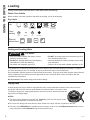
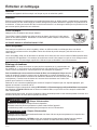
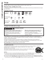
Fabric Care Labels
Below are fabric care label “symbols” that affect the clothing you will be laundering.
Dry Labels
Always follow fabric manufacturer’s care label when laundering.
As a general rule, if clothes are sorted properly for the washer, they are sorted properly for the dryer. Try also to
sort items according to size. For example, do not dry a sheet with socks or other small items.
Do not add fabric softener sheets once the load has become warm. They may cause fabric softener stains. Bounce
®
Fabric Conditioner Dryer Sheets have been approved for use in this dryer when used in accordance with the
manufacturer’s instructions.
Do not overload. This wastes energy and causes wrinkling.
• Keep flammable materials and vapors, such as
gasoline, away from dryer.
• DO NOT dry anything that has ever had anything
flammable on it (even after washing).
• No washer can completely remove oil.
• DO NOT dry anything that has ever had any type of oil
on it (including cooking oils).
• Items containing foam, rubber, or plastic must be dried
on a clothesline.
• Failure to do so can result in death, explosion, or fire.
Sorting and Loading Hints
Tumble
dry
Dry
Normal
Permanent Press/
wrinkle resistant
Gentle/
delicate
Do not tumble dry
Do not dry
(used with
do not wash)
Heat
setting
High Medium Low No heat/air
Special
instructions
Line dry/
hang to dry
Drip dry
Dry flat
In the shade
- Fire Hazard
WARNING
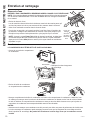
Drying Rack
A handy drying rack may be used for drying delicate items such as washable sweaters. Place items flat on the
drying rack and block such items as wool sweaters and delicate fabrics. Dry with low heat.
To install the drying rack, extend the drying rack into the dryer drum and rest the front two
legs on the front angled ledge.
NOTES:
Ŷ
The drying rack is designed for use with the Timed Dry cycle. Use with sensor cycles
may result in damp items or extended cycle times.
Ŷ
Do not use this drying rack when there are other clothes in the dryer, that are not placed on the rack.
Ŷ
The drying rack, WE01X26416, is available as an accessory. Order on-line at GEApplianceparts.com, 24 hours
a day or by phone at 877.959.8688 during normal business hours.

49-90571-3 9
CARE AND CLEANING
Care and cleaning
Exterior
Wipe or dust any spills or washing compounds with a damp cloth. Dryer control panel and finishes may be damaged
by some laundry pretreatment soil and stain remover products. Apply these products away from the dryer. The fabric
may then be washed and dried normally. Damage to your dryer caused by these products is not covered by your
warranty.
Stainless Steel
To clean stainless steel surfaces use a damp cloth with a mild, non-abrasive cleaner suitable for stainless steel
surfaces. Remove the cleaner residue and then dry with a clean cloth.
The stainless steel used to make the dryer drum provides the highest reliability available in a GE Appliances dryer.
If the dryer drum should be scratched or dented during normal use, the drum will not rust or corrode. These surface
blemishes will not affect the function or durability of the drum.
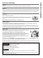
Interior
The interior of the appliance should be cleaned once a year by qualified service personnel.
Lint Filter
Clean the lint filter before each use.
Pull out the lint filter. Moisten your fingers and remove the captured lint. Once clean, slide
the filter back into position. Have a qualified technician vacuum the lint from the dryer once
a year.
NEVER OPERATE THE DRYER WITHOUT ITS FILTER IN PLACE.
Drum Lamp
NOTE: The drum lamp is not consumer replaceable on models where there is a flat cover
over an LED bulb. If this light should ever stop working, call for service.
For models that have a domed cover over the bulb secured by a screw:
Before replacing the light bulb, be sure to unplug the dryer power cord or disconnect the
dryer at the household distribution panel by removing the fuse or switching off the circuit
breaker. Reach above dryer opening from inside the drum to locate the light.
Remove the screw and the plastic cover to access the bulb. Replace with the appropriate
bulb and then reaffix the cover and screw.
Order replacement bulb WE11X26351 on-line at GEApplianceparts.com, by phone at 877.959.8688 during normal
business hours, or purchase appliance bulb 7C7 from your local retailer.
When the door is opened, the drum lamp automatically turns on and remains on for 2 minutes. When the door is closed,
the drum lamp will remain on for 30 seconds.
Disconnect power supply before servicing.
Replace all parts and panels before operating.
Failure to do so can result in death or electrical shock.
WARNING
- Shock Hazard
Certain internal parts are intentionally not grounded and may present a risk of electric shock only during
servicing.
Service personnel – DO NOT contact the following parts while the appliance is energized: motor start capacitor,
motor metal holder, and drum wheel shaft.
- Electrical Shock Hazard
WARNING

10 49-90571-3
Care and cleaning
CARE AND CLEANING
Water Tank
REMOVE THE CONDENSED WATER IN THE TANK AFTER EVERY DRYING CYCLE.
NOTE: If drain hose is installed, emptying the water tank is not required. See the
CONNECTING THE DRAIN HOSE section in the Installation Installations of this manual.
• Pull out the water tank.
When removing the water tank from the product, hold it using both hands as it is
heavy and take care not to spill any water inside the tank.
• Remove the condensed water inside the water tank.
To avoid over filling, which could lead to water leaking outside the unit, drain
water left in water tank after each cycle. Over filling will cause cycle to stop
prematurely until emptied.
NOTE: When the Empty Tank indicator light is on, the dryer will not operate until
the tank is emptied and the indicator has been cleared. Press the Start button and
the indicator light will turn off and the dryer will resume the cycle.
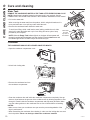
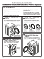
Condenser
THE CONDENSER SHOULD BE CLEANED ONCE PER MONTH.
• Open the condenser compartment cover.
• Unlock both locking tabs.
• Remove the condenser box from
the condenser compartment.
• Clean the condenser box and inside the condenser compartment completely. Use tap
water to clean between the grooves of the condenser box by allowing tap water to flow
through it. Reach inside the condenser compartment and wipe away all debris. Make
sure the rubber gaskets on the condenser box are free of debris before reinstalling.
NOTES:
• Make sure to clean your condenser once per month to prevent degradation of the
dryer’s performance.
• When assembling the condenser after cleaning it, make sure the locking tabs are set to
the lock position. Never run the dryer without the condenser installed.
Unlock
Drain hole
is on the
top rear of
the drawer

49-90571-3 11
NOTES
Notes

12 49-90571-3
Installation
Dryer
Instructions
If you have any questions, call GE Appliances at 800.GE.CARES
(800.432.2737)
or visit our Website at: GEAppliances.com
In Canada, call 800.561.3344
or visit www.GEAppliances.ca
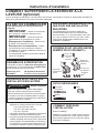
BEFORE YOU BEGIN
Read these instructions completely and carefully.
• IMPORTANT – Save these instructions for
local electrical inspector’s use.
• IMPORTANT – Observe all governing
codes and ordinances.
• Install the clothes dryer according to the
manufacturer’s instructions and local codes.
• Note to Installer – Be sure to leave these
instructions with the Consumer.
• Note to Consumer – Keep these instructions for
future reference.
• Clothes dryer installation must be performed by a
qualified installer.
• Before the old dryer is removed from service or
discarded, remove the dryer door.
• Service information and the wiring diagram are
located in the control console.
• Do not allow children on or in the appliance. Close
supervision of children is necessary when the
appliance is used near children.
• Proper installation is the responsibility of the installer.
• Product failure due to improper installation is not
covered under the Warranty.
• Install the dryer where the temperature is above
50°F for satisfactory operation of the dryer control
system.
• Risk of Fire - Clothes dryer installation must be
performed by a qualified installer.
• Install the clothes dryer according to these
instructions and local codes.
• DO NOT install or store this appliance in any
location where it could be exposed to water or
weather.
• To reduce the risk of severe injury or death, follow
all installation instructions.
• Save these instructions. (Installers: Be sure to
leave these instructions with the customer.)
- Fire Hazard
WARNING
If you are planning to stack the washer and dryer, order
Stacking Kit number GFA24KITL to be used for this
dryer. Kit sold separately.

49-90571-3 13
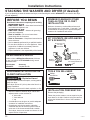
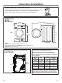
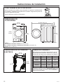
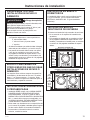
*NOTE:
With leveling legs retracted: 33-1/4 (84.5 cm)
With leveling legs fully extended: 33-5/8 (85.4 cm)
Stacked: 66-1/2” (168.9 cm)
Installation Instructions
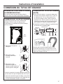
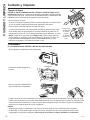
Tilt the dryer sideways and remove the foam shipping pads by pulling at the sides and
breaking them away from the dryer legs. Be sure to remove all of the foam pieces
around the legs.
Remove the bag containing the literature.
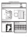
UNPACKING YOUR DRYER
DRYER
DIMENSIONS
Front
View
23-7/16”
(59.5 cm)
*33-1/4”
(84.5 cm)
Side View
25-1/4” (64.1 cm)
42-13/16” (108.7 cm)
ELECTRICAL CONNECTION
DIMENSIONS
POWER CORDS
GE Appliances strongly recommends the use of
factory specified parts. Select the power cord to fit your
installation requirements.
Order on-line at GEApplianceparts.com today,
24 hours a day or by phone at 877.959.8688 during
normal business hours. In Canada, visit your local
GE Appliances parts distributor or call 800.661.1616
or
GEAppliances.ca/en/products/parts-filters-accessories.
Part Number Type Length Amperage
WX9X2 3-Prong 4 Feet 30
WX9X3 3-Prong 5 Feet 30
WX9X4 3-Prong 6 Feet 30
WX9X18 4-Prong 4 Feet 30
WX9X19 4-Prong 5 Feet 30
WX9X20 4-Prong 6 Feet 30
Back
View
30”
(76.2 cm)
20-1/2”
(52.1 cm)
*33-1/4”
(84.5 cm)

14 49-90571-3
Installation Instructions
MOBILE OR MANUFACTURED
HOME INSTALLATION
• Installation MUST conform to the
MANUFACTURED HOME CONSTRUCTION
AND SAFETY STANDARD, TITLE 24, PART
3280 or STANDARD FOR MOBILE HOMES
CAN/CSA-Z240 MH, or, when such standards
are not applicable, with AMERICAN NATIONAL
STANDARD FOR MOBILE HOME, ANSI/NFPA
NO. 501B.
• Provide an opening with a free area of at least 25
square inches for introduction of outside air into
the dryer room.
• See the sections for electrical connection information.
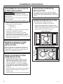
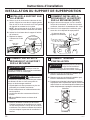
REQUIREMENTS FOR ALCOVE OR
CLOSET INSTALLATION
Keep flammable materials and vapors, such as gasoline,
away from dryer.
Place dryer at least 18” (46 cm) above the floor for a
garage installation.
Failure to do so can result in death, explosion, or fire.
• Minimum clearance between dryer cabinet and
adjacent walls or other surfaces is:
0” either side
1” front and rear
1” top
• Consideration must be given to provide adequate
clearance for installation and service.
• Closet doors must be louvered or otherwise
ventilated and have at least 60 square inches of
open area. If the closet contains both a washer
and a dryer, doors must contain a minimum of 120
square inches of open area.
MINIMUM CLEARANCE OTHER
THAN ALCOVE OR CLOSET
INSTALLATION
Minimum clearance to combustible surfaces and
for air opening are: 0” both sides, 1” rear and 1” top.
Consideration must be given to provide adequate
clearance for installation and service.
- Explosion Hazard
WARNING
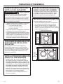
UNDERCOUNTER INSTALLATION
If an undercounter installation is desired:
• No special dryer installation kit is required.
• If the dryer is installed alone, a minimum of 60
square inches of open area is required. If a washer
and dryer are installed together, a minimum of 120
square inches of open area is required.
BATHROOM OR BEDROOM
INSTALLATION
The installation must conform with local codes or,
in the absence of local codes, with the NATIONAL
ELECTRICAL CODE, ANSI/NFPA NO. 70 (for electric
dryers).
60
square
inches
min.
open
area
Dryer Installed Alone
Countertop and side cabinets
Washer and Dryer Installed Together
Countertop and side cabinets
120
square
inches
min.
open
area

49-90571-3 15
Installation Instructions
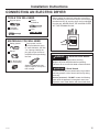
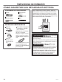
CONNECTING AN ELECTRIC DRYER
Before making the electrical connection, turn off the
circuit breaker(s) or remove the dryer’s circuit fuse(s) at
the electrical box. Be sure the dryer cord is unplugged
from the wall. NEVER LEAVE THE ACCESS COVER
OFF THE TERMINAL BLOCK.
MATERIALS YOU WILL NEED
Safety glasses
Gloves
Dryer power cord kit
(not provided with dryer)
UL rated 120/240V, 30A with
3 or 4 prongs. Identify the
plug type as per the house
receptacle before purchasing
line cord.
Stacking installations may
require a power cord up to 6
feet in length.
TOOLS YOU WILL NEED
Slip-joint pliers
Flat-blade
screwdriver
Phillips
screwdriver
Level
3/4” Strain relief
(UL recognized)
Disconnect power supply before servicing.
Replace all parts and panels before operating.
Failure to do so can result in death or electrical shock.
WARNING
- Shock Hazard
Certain internal parts are intentionally not grounded
and may present a risk of electric shock only during
servicing.
Service personnel – DO NOT contact the following
parts while the appliance is energized: motor start
capacitor, motor metal holder, and drum wheel shaft.
- Electrical Shock Hazard
WARNING

16 49-90571-3
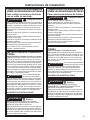
For direct wire connections:
Use 10 gauge copper wire.
Use a UL-listed strain relief.
Disconnect power before making electrical connections.
Connect neutral wire (white or center wire) to center
terminal.
Ground wire (green or bare wire) must be connected to
green ground connector.
Connect remaining two supply wires to remaining two
terminals.
Securely tighten all electrical connections.
Replace the terminal block cover.
Failure to do so can result in death, fire or electrical shock.
GROUNDING INSTRUCTIONS
For a permanently connected dryer: This dryer
must be connected to a grounded metal, permanent
wiring system, or an equipment-grounding conductor
must be run with the circuit conductors and
connected to the equipment-grounding terminal on
the appliance.
Improper connection of the
equipment-grounding conductor can
result in a risk of electric shock. Check with a qualified
electrician, or service representative or personnel, if
you are in doubt as to whether the appliance is properly
grounded.
SAVE THESE INSTRUCTIONS
- Fire Hazard
WARNING
WARNING
Use a new UL-listed 240V 30 amp dryer power supply
cord with closed ring terminals or spade terminals with
upturned ends.
Use a UL-listed strain relief.
Disconnect power before making electrical connections.
Connect neutral wire (white or center wire) to center
terminal.
Ground wire (green or bare wire) must be connected to
green ground connector.
Connect remaining two supply wires to remaining two
terminals.
Securely tighten all electrical connections.
Replace the terminal block cover.
Failure to do so can result in death, fire or electrical shock.
For electrical connections using a
power cord:
GROUNDING INSTRUCTIONS
For a grounded, cord-connected dryer: This dryer
must be grounded. In the event of a malfunction or
breakdown, grounding will reduce the risk of electric
shock by providing a path of least resistance for
electric current. This dryer uses a cord having an
equipment-grounding conductor and a grounding
plug. The plug must be plugged into an appropriate
outlet that is properly installed and grounded in
accordance with all local codes and ordinances.
Improper connection of the
equipment-grounding conductor can
result in a risk of electric shock. Check with a qualified
electrician, or service representative or personnel, if
you are in doubt as to whether the appliance is properly
grounded. DO NOT modify the plug on the power supply
cord. If it will not fit the outlet, have a proper outlet
installed by a qualified electrician.
SAVE THESE INSTRUCTIONS
- Fire Hazard
WARNING
WARNING
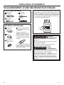
ELECTRICAL CONNECTION
INFORMATION FOR ELECTRIC
DRYERS
ELECTRICAL CONNECTION
INFORMATION FOR ELECTRIC
DRYERS
Installation Instructions
TO PREVENT ELECTRIC SHOCK, DISCONNECT
POWER BEFORE SERVICING.
This dryer should be connected to an individual branch
circuit with 10 gauge copper wire minimum through a
30 amp fuse or circuit breaker. DO NOT fuse neutral.
Use copper conductors only.
- Electrical Shock Hazard
WARNING
TO PREVENT ELECTRIC SHOCK, DISCONNECT
POWER BEFORE SERVICING.
This dryer should be connected to an individual branch
circuit with 10 gauge copper wire minimum through a
30 amp fuse or circuit breaker. DO NOT fuse neutral.
Use copper conductors only.
- Electrical Shock Hazard
WARNING

49-90571-3 17
Installation Instructions
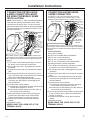
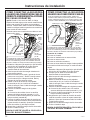
CONNECTING DRYER USING
3-WIRE CONNECTION
CONNECTING DRYER USING
4-WIRE CONNECTION (MUST
BE USED FOR MOBILE HOME
INSTALLATION)
NOTE: Since January 1, 1996, the National Electrical
Code requires that new constructions use a 4-wire
connection to an electric dryer. A 4-wire cord must
also be used where local codes do not permit grounding
through the neutral. 3-wire connection is NOT for use
on new construction.
1. Turn off the circuit breaker(s) (30 amp) or remove
the dryer’s circuit fuse at the electrical box.
2. Be sure the dryer cord is unplugged from the wall
receptacle.
3. Remove the power cord cover located at the upper
back.
4. Remove green ground screw and retain for use in
Step 7. Remove center screw (marked N) in terminal
block. Remove and discard ground strap.
5. Install 3/4 in. UL-recognized strain relief to power
cord entry hole. Bring power cord through strain
relief and bracket.
6. Connect power cord as follows:
A. Connect the 2 hot lines to the outer screws of the
terminal block (marked L1 and L2).
B. Connect the neutral (white) line to the center of
the terminal block (marked N).
7. Attach ground wire of power cord with the green
ground screw (hole above strain relief bracket).
Tighten all terminal block screws (3) securely.
8. Properly secure power cord to strain relief and
bracket.
9. Reinstall the cover.
NEVER LEAVE THE COVER OFF OF THE
TERMINAL BLOCK.
NEVER LEAVE THE COVER OFF OF THE
TERMINAL BLOCK.
3-wire Connection
Not for use in Canada.
DO NOT use for Mobile Home Installations.
NOT for use on new construction.
NOT for use on recreational vehicles.
NOT for use in areas where local codes prohibit
grounding through the neutral conduction.
1. Turn off the circuit breaker(s) (30 amp) or remove
the dryer’s circuit fuse at the electrical box.
2. Be sure the dryer cord is unplugged from the wall
receptacle.
3. Remove the power cord cover located at the upper
back.
4. Install 3/4-in. UL-recognized strain relief to power
cord entry hole. Bring power cord through strain
relief and bracket.
5. Connect power cord as follows:
A. Connect the 2 hot lines to the outer screws of
the terminal block (marked L1 and L2).
B. Connect the neutral (white) line to the center of
the terminal block (marked N).
6. Be sure ground strap is connected to green ground
screw on cabinet rear. Tighten all terminal block
screws (3) securely.
7. Properly secure power cord to strain relief and
bracket.
8. Reinstall the cover.
L1
N
L2
Green wire
from power
cord
3/4” Strain
Relief and
Bracket
Cover
4 #10 AWG minimum copper conductors or 120/240V 30A
power supply cord kit marked for use with dryers and provided
with closed loop or spade terminals with upturned ends (not
supplied).
White Wire
Black
or Red
Wire
Black
or
Red
Wire
If required, by local code, install external ground (not
provided) to grounded metal, cold water pipe, or other
established ground determined by a qualified electrician.
L1
N
L2
Black or Red Wire
3/4” Strain
Relief and
Bracket
Cover
3 #10 AWG minimum copper conductors or 120/240V 30A
power supply cord kit marked for use with dryers and provided
with closed loop or spade terminals with upturned ends (not
supplied).
Ground
Strap
White Wire
Black
or Red
Wire

18 49-90571-3
Installation Instructions
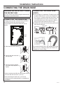
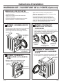
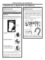
CONNECTING THE DRAIN HOSE
DRAINING WATER WITHOUT USING
THE WATER TANK
You can use the dryer without using the water tank by
following the procedures below.
CONNECTING THE DRAIN HOSE
The dryer can pump the condensed water outside of
the DRYER directly with drain hose provide.
The procedures to connect the drain hose are as
follows.
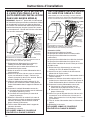
1. Disconnect the drain hose A.
2. Connect the drain hose A to
the other hole.
3. Connect accessory hose B
(long drain hose) adjacent to
hose A.
• When connecting hose B, take care that the height of
the hose does not exceed 47” (120 cm).
• After connecting the drain hose, you can now
directly drain the condensed water to a standpipe or
washstand.
CONNECTING THE DRAIN HOSE
(CONT.)
4. Over the edge of a wash basin: The drain hose must
be placed lower than 47” (120 cm) and higher than
30” (76 cm). To keep the drain hose spout bent, use
the supplied plastic hose guide. Secure the guide
to the wall with a hook or to the tap with a piece of
string to prevent the drain hose from moving.
5. Assemble the drain hose and the hose guide and fix
them with the cable-tie.
Do not push the drain hose in the standpipe any further
than 4” (10 cm). Pushing the drain hose further in the
standpipe can cause leaking.
Back
View
A
A
B
47”
(120 cm)
Max.
Drain Hose
Hose Guide
Cable Ties

49-90571-3 19
Installation Instructions
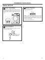
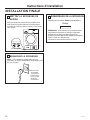
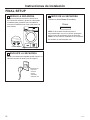
LEVEL THE DRYER
Raise
Lower
PLUG DRYER IN
Ensure proper
ground exists
before use.
1
FINAL SETUP
2
DRYER STARTUP
Press the Power button.
NOTE: If the dryer has been exposed to temperatures
below freezing for an extended period of time, allow
it to warm up before pressing Power. Otherwise, the
display will not come on.
The dryer is now ready for use.
3
NOTE: Stacking installations may require a power
cord up to 6 feet in length.
Stand the dryer upright near the final location and
adjust the four leveling legs at the corners to ensure
that the dryer is level from side to side and front to
rear.
Power

20 49-90571-3
Installation Instructions
BEFORE YOU BEGIN
Read these instructions completely and carefully.
• IMPORTANT – Save these instructions for
local electrical inspector’s use.
• IMPORTANT – Observe all governing
codes and ordinances.
• Note to Installer – Be sure to leave these
instructions with the Consumer.
• Note to Consumer – Keep these instructions for
future reference.
• Service must be performed by a qualified installer.
• Do not allow children on or in the appliance. Close
supervision of children is necessary when the
appliance is used near children.
• Proper installation is the responsibility of the installer.
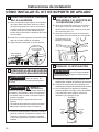
REQUIREMENTS FOR ALCOVE OR
CLOSET INSTALLATION
Keep flammable materials and vapors, such as gasoline,
away from dryer.
Place dryer at least 18” (46 cm) above the floor for a
garage installation.
Failure to do so can result in death, explosion, or fire.
• Minimum clearance between dryer cabinet and
adjacent walls or other surfaces is:
0” either side
1” front and rear
1” top
• Consideration must be given to provide adequate
clearance for installation and service.
• Closet doors must be louvered or otherwise
ventilated and have at least 60 square inches of
open area. If the closet contains both a washer
and a dryer, doors must contain a minimum of 120
square inches of open area.
MINIMUM CLEARANCE OTHER
THAN ALCOVE OR CLOSET
INSTALLATION
Minimum clearance to combustible surfaces and
for air opening are: 0” both sides, 1” rear and 1” top.
Consideration must be given to provide adequate
clearance for installation and service.
- Explosion Hazard
WARNING
GE APPLIANCES STACK KIT
Order on-line at GEApplianceParts.com, 24 hours
a day or by phone at 877.959.8688 during normal
business hours.
Part Number Accessory
GFA24KITL Complete Stack Kit
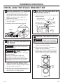
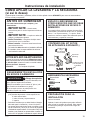
STACKING THE WASHER AND DRYER (if desired)
If you are planning to stack the washer and dryer, order Stacking Kit number GFA24KITL to be used for this dryer.
Kit sold separately.
INSTALLATION PREPARATION
Remove the packaging.
Flatten the product carton to use as a pad to lay the
dryer down on its side. Continue using the carton to
protect the finished floor in front of the installation
location.
TOOLS YOU WILL NEED
Level
Phillips
screwdriver
Gloves
KIT CONTENTS (GE APPLIANCES
KIT # GFA24KITL)
Screws (2) Long
For dryer
attachment
Bracket-
stack (R)
Bracket-
stack (L)
Screws (6) Short
For washer attachment
La page est en cours de chargement...
La page est en cours de chargement...
La page est en cours de chargement...
La page est en cours de chargement...
La page est en cours de chargement...
La page est en cours de chargement...
La page est en cours de chargement...
La page est en cours de chargement...
La page est en cours de chargement...
La page est en cours de chargement...
La page est en cours de chargement...
La page est en cours de chargement...
La page est en cours de chargement...
La page est en cours de chargement...
La page est en cours de chargement...
La page est en cours de chargement...
La page est en cours de chargement...
La page est en cours de chargement...
La page est en cours de chargement...
La page est en cours de chargement...
La page est en cours de chargement...
La page est en cours de chargement...
La page est en cours de chargement...
La page est en cours de chargement...
La page est en cours de chargement...
La page est en cours de chargement...
La page est en cours de chargement...
La page est en cours de chargement...
La page est en cours de chargement...
La page est en cours de chargement...
La page est en cours de chargement...
La page est en cours de chargement...
La page est en cours de chargement...
La page est en cours de chargement...
La page est en cours de chargement...
La page est en cours de chargement...
La page est en cours de chargement...
La page est en cours de chargement...
La page est en cours de chargement...
La page est en cours de chargement...
La page est en cours de chargement...
La page est en cours de chargement...
La page est en cours de chargement...
La page est en cours de chargement...
La page est en cours de chargement...
La page est en cours de chargement...
La page est en cours de chargement...
La page est en cours de chargement...
La page est en cours de chargement...
La page est en cours de chargement...
La page est en cours de chargement...
La page est en cours de chargement...
La page est en cours de chargement...
La page est en cours de chargement...
La page est en cours de chargement...
La page est en cours de chargement...
La page est en cours de chargement...
La page est en cours de chargement...
La page est en cours de chargement...
La page est en cours de chargement...
-
 1
1
-
 2
2
-
 3
3
-
 4
4
-
 5
5
-
 6
6
-
 7
7
-
 8
8
-
 9
9
-
 10
10
-
 11
11
-
 12
12
-
 13
13
-
 14
14
-
 15
15
-
 16
16
-
 17
17
-
 18
18
-
 19
19
-
 20
20
-
 21
21
-
 22
22
-
 23
23
-
 24
24
-
 25
25
-
 26
26
-
 27
27
-
 28
28
-
 29
29
-
 30
30
-
 31
31
-
 32
32
-
 33
33
-
 34
34
-
 35
35
-
 36
36
-
 37
37
-
 38
38
-
 39
39
-
 40
40
-
 41
41
-
 42
42
-
 43
43
-
 44
44
-
 45
45
-
 46
46
-
 47
47
-
 48
48
-
 49
49
-
 50
50
-
 51
51
-
 52
52
-
 53
53
-
 54
54
-
 55
55
-
 56
56
-
 57
57
-
 58
58
-
 59
59
-
 60
60
-
 61
61
-
 62
62
-
 63
63
-
 64
64
-
 65
65
-
 66
66
-
 67
67
-
 68
68
-
 69
69
-
 70
70
-
 71
71
-
 72
72
-
 73
73
-
 74
74
-
 75
75
-
 76
76
-
 77
77
-
 78
78
-
 79
79
-
 80
80


GE GFT14ESSLWW Le manuel du propriétaire
- Catégorie
- Sèche-linge
- Taper
- Le manuel du propriétaire
- Ce manuel convient également à
dans d''autres langues
- English: GE GFT14ESSLWW Owner's manual
- español: GE GFT14ESSLWW El manual del propietario
Documents connexes
-
GE GFT14ESSMWW Front Load Ventless Condenser Electric Dryer Le manuel du propriétaire
-
GE GFT14ESSMWW Le manuel du propriétaire
-
-
-
-
-
-
-
-
