General International TS4001 Manuel utilisateur
- Taper
- Manuel utilisateur

TS4001 man v.170807
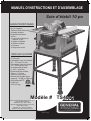
SETUP & OPERATION MANUAL
Model #
General International Power Products, LLC
6243 Industrial Parkway
Whitehouse, OH 43571 USA
General International Power Products Ltd.
8360 Champ d’Eau
Montréal, QC H1P 1Y3 Canada
website: www.gipowerproducts.com
FEATURES
● Powerful 13 amp motor
● Cast aluminum work table
● Riving knife
● Anti-kickback pawls
● Includes:
● 10 in. 24 tooth tungsten
carbide tipped saw blade
● Rip fence
● Miter gauge
● Push stick
● Metal stand
SPECIFICATIONS
● 120 V ~ 60 Hz 13 A
● 5700 rpm
● Max. cutting height at 90°:
2-7/8 in. (73 mm)
● Max. cutting height at 45°:
2-5/8 in.(65 mm)
● Tilting range: 0° to 45° left
● Table dimensions: 26 in. x 17-
1/2 in. (660 mm x 440 mm)
● Table height (on stand):
35-3/8 in. (900 mm)
● ETL certication
● Net weight:
44 lb. (20 kg)
TS4001
10 inch Table Saw
3150598

ENGLISH
2
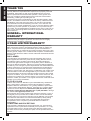
THANK YOU
for choosing this General International machine. This tool has been
carefully tested and inspected before shipment and if properly used and
maintained, will provide you with years of reliable service. To ensure
optimum performance and trouble-free operation, and to get the most
from your investment, please take the time to read this manual before
assembling, installing and operating the unit.
The manual’s purpose is to familiarize you with the safe operation, basic
function, and features of this tool as well as the set-up, maintenance and
identication of its parts and components. This manual is not intended
as a substitute for formal woodworking instruction, nor to oer the user
instruction in the craft of woodworking. If you are not sure about the safety
of performing a certain operation or procedure, do not proceed until you
can conrm, from knowledgeable and qualied sources, that it is safe to do so.
Once you’ve read through these instructions, keep this manual handy for
future reference.
GENERAL
®
INTERNATIONAL
WARRANTY
All component parts of General
®
International products are carefully
inspected during all stages of production and each unit is thoroughly
inspected upon completion of assembly.
2
-
YEAR LIMITED WARRANTY
All products are warranted for a period of 2 years (24 months) from the
date of purchase. General
®
International agrees to repair or replace any
part or component which upon examination, proves to be defective in
either workmanship or material to the original purchaser during this 2-year
warranty period, subject to the “conditions and exceptions” as listed below.
Repairs made without the written consent of General International will void
the warranty.
DISCLAIMER
The information and specications in this manual pertain to the unit as
it was supplied from the factory at the time of printing. Because we are
committed to making constant improvements, General International
reserves the right to make changes to components, parts or features of
this unit as deemed necessary, without prior notice and without obligation
to install any such changes on previously delivered units. Reasonable care
is taken at the factory to ensure that the specications and information in
this manual corresponds with that of the unit with which it was supplied.
However, special orders and “after factory” modications may render some
or all information in this manual inapplicable to your machine. Further, as
several generations of this tool model and several versions of this manual
may be in circulation, if you own an earlier or later version of this unit, this
manual may not depict your machine exactly. If you have any doubts or
questions contact your retailer or our support line with the model and serial
number of your unit for clarication.
TO FILE A CLAIM
To le a claim under our Standard 2-year Limited Warranty, all defective
parts, components or machinery must be returned freight or postage
prepaid to General
®
International, or to a nearby distributor, repair center
or other location designated by General
®
International. For further details
contact our service department: USA toll-free (844) 877-5234 or (419)
877-5234 / Canada toll-free (888) 949-1161 or (604) 420-2299 or through
our website: www.gipowerproducts.com.
Along with the return of the product being claimed for warranty, a copy of
the original proof of purchase and a “letter of claim” must be included (a
warranty claim form can also be used and can be obtained, upon request,
from General
®
International or an authorized distributor) clearly stating
the model and serial number of the unit (if applicable) and including
an explanation of the complaint or presumed defect in material or
workmanship.
CONDITIONS AND EXCEPTIONS
This coverage is extended to the original purchaser only. Prior warranty
registration is not required but documented proof of purchase, i.e. a copy
of original sales invoice or receipt showing the date and location of the
purchase as well as the purchase price paid, must be provided at the time
of claim.

ENGLISH
3
170807
Warranty does not include failures, breakage or defects deemed after
inspection by General
®
International to have been directly or indirectly
caused by or resulting from; improper use, or lack of or improper
maintenance, misuse or abuse, negligence, accidents, damage in
handling or transport, or normal wear and tear of any generally considered
consumable parts or components.
Repairs made without the written consent of General
®
International will
void all warranty.
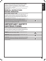
READ ALL INSTRUCTIONS
BEFORE OPERATING
SAVE THESE INSTRUCTIONS
Before attempting to operate your new tool, please read these instructions
thoroughly. You will need these instructions for the safety warnings,
precautions, assembly, operation, maintenance procedures, parts list and
diagrams. Keep your invoice with these instructions. Write the invoice
number on the inside of front cover. Keep the instructions and invoice in a
safe, dry place for future reference.
THE WARNINGS, CAUTIONS AND INSTRUCTIONS discussed
in this instruction manual cannot cover all possible conditions or
situations that could occur. It must be understood by the operator that
common sense and caution are factors which cannot be built into this
product, but must be supplied by the operator.
IMPORTANT SAFETY
INSTRUCTIONS
The purpose of safety symbols is to attract your attention to possible
hazards. The safety symbols, and the explanations with them, deserve
your careful attention and understanding. The safety warnings do not, by
themselves, eliminate any danger. The instructions or warnings they give
are not substitutes for proper accident prevention measures.
DANGER! Indicates an imminently hazardous situation which, if not
avoided, will result in serious injury or death.
WARNING! Indicates an imminently hazardous situation which, if not
avoided, could result in serious injury or death.
CAUTION: Indicates an imminently risky situation which, if not avoided,
could result in minor injuries or slight injury. It may also be used to notify
the user to remain alert regarding unsafe practises which may cause
property damage.

ENGLISH
4
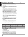
WARNINGS AND CAUTIONS
1. KEEP WORK AREA CLEAN. Cluttered areas invite injuries.
2. CONSIDER WORK AREA ENVIRONMENT. Don’t use bench tools in
damp, wet, or poorly lit locations. Don’t expose your tool to rain. Keep
the work area well lit. Don’t use tools in the presence of ammable
gases or liquids.
3. KEEP CHILDREN AND BY STANDERS AWAY. All children should be
kept away from the work area. Don’t let them handle machines, tools or
extension cords. Visitors can be a distraction and are dicult to protect
from injury.
4. GROUNDED TOOLS MUST BE PLUGGED INTO AN OUTLET THAT
ITSELF IS PROPERLY INSTALLED AND GROUNDED. Grounding
provides a low-resistance path to carry electricity to ground away from
the operator, should the tool malfunction electrically. Do not remove the
grounding prong from the plug or alter the plug in any way. If in doubt as
to whether the outlet is properly grounded according to code, check with
a qualied electrician.
5. GUARD AGAINST ELECTRIC SHOCK. Prevent body contact with
grounded surfaces: pipes, radiators, ranges, and refrigerator enclosures.
When your body is grounded the risk of electric shock increases. When
working wherever “live” electrical wires may be encountered, try to
ascertain whether there is a danger of shock. Even so, DO NOT TOUCH
ANY METAL PARTS OF THE TOOL while using it. Hold the tool only by
the plastic grip to prevent electric shock if you contact a live wire.
6. DO NOT ABUSE THE CORD. Never carry your bench tool by the cord
or pull on the cord to unplug it. Protect the cord from potential sources
of damage: heat, oil & solvents, sharp edges, or moving parts. Replace
damaged cords immediately.
7. WHEN WORKING OUTDOORS, USE AN OUTDOOR-RATED
EXTENSION CORD. An extension cord rated for outdoor use must be
marked “W-A” or “W”.
8. DO NOT EXPOSE ELECTRICAL BENCH TOOLS TO MOISTURE.
Rain or wet conditions can cause water to enter the tool and lead to
electric shock.
9. USE PROPER EXTENSION CORD. Make sure your extension cord is
in good condition. When using an extension cord, be sure to use one
heavy enough to carry the current your product will draw. An undersized
cord will cause a drop in line voltage resulting in loss of power and
overheating. The table below shows the correct size to use depending
on the cord length and name plate amperage rating. If in doubt, use
the next heavier gauge. The smaller the gauge number, the heavier the
cord.
Total Extension Cord Length
Amp Rating Feet Meters Feet Meters Feet Meters Feet Meters
25 8 50 15 100 30 125 40
3-10 amp 18 ga. 16 ga. 14 ga. 14 ga.
10.1 - 12 amp 16 ga. 16 ga. 14 ga. 14 ga.
12.1 - 16 amp 14 ga. 12 ga. Not Recommended
Use only UL or CSA approved extension cords
10. STORE IDLE EQUIPMENT. Store equipment in a dry area to inhibit
rust. Equipment also should be in a high location or locked up to keep
out of reach of children.
11. DON’T FORCE THE TOOL. It will do the job better and more safely at
the rate for which it was intended.
12. USE THE RIGHT TOOL. Don’t force a small tool or attachment to do
the work of a larger industrial tool. Don’t use a tool for a purpose for
which it was not intended.
13. DRESS PROPERLY. Don’t wear loose clothing or jewelry; they can
be caught in moving parts. Protective, non-electrically conductive
gloves and non-skid footwear are recommended when working. Wear
protective hair covering to contain long hair and keep it from harm.

ENGLISH
5
170807
14. USE EYE PROTECTION. Use a full-face mask if the work you’re doing
produces metal lings, dust or wood chips. Goggles are acceptable in
other situations. Wear a clean dust mask if the work involves creating a
lot of ne or coarse dust.
15. SECURE WORK. Use clamps or a vise to hold the work. It’s safer than
using your hands and it frees both hands to operate the tool.
16. DON’T OVERREACH. Keep proper footing and balance at all times. Do
not reach over or across machines that are running.
17. MAINTAIN TOOLS WITH CARE. Keep tools sharp and clean for
better and safer performance. Follow instructions for lubricating and
safe performance. Follow instructions for lubricating and changing
accessories. Keep handles dry, clean and free from oil and grease.
18. AVOID UNINTENTIONAL STARTING. Be sure the switch is in the OFF
position before plugging in.
19. ALWAYS CHECK AND MAKE SURE TO REMOVE ANY ADJUSTING
KEYS OR WRENCHES BEFORE TURNING THE TOOL ON. Left
attached, these parts can y o a rotating part and result in personal
injury.
20. DO NOT USE THE TOOL IF IT CANNOT BE SWITCHED ON OR OFF.
Have your tool repaired before using it.
21. DISCONNNECT THE PLUG FROM POWER BEFORE MAKING
ANY ADJUSTMENTS. Changing attachments or accessories can be
dangerous if the tool could accidentally start.
22. STAY ALERT. Watch what you are doing & use common sense. Don’t
operate any tool when you are tired.
23. CHECK FOR DAMAGED PARTS. Before using this tool, any part
that is damaged should be carefully checked to determine that it will
operate properly and perform its intended function. Check for alignment
of moving parts, binding of moving parts, breakage of parts, mountings,
and other conditions that may aect its operation. Inspect screws and
tighten any ones that are loose. Any part that is damaged should be
properly repaired or replaced by an authorized service center unless
otherwise indicated elsewhere in the instruction manual. Have defective
switches replaced by an authorized service center. Don’t use the tool if
switch does not turn it on and o properly.
24. KEEP CUTTING TOOLS SHARP TO ENSURE LESS STRESS ON
THE MOTOR.
25. REPLACEMENT PARTS. When servicing, use only identical
replacement parts.
26. SERVICE AND REPAIRS SHOULD BE MADE BY QUALIFIED
REPAIR TECHNICIANS AT AN AUTHORIZED REPAIR CENTER.
Improperly repaired tools could cause serious shock or injury.
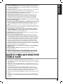
SAFETY PRECAUTIONS FOR
TABLE SAW
● WOOD ONLY. This tool is designed for woodcutting only.
● DAMAGED OR WARPED SAW BLADES should not be used. They are
out of balance and could cause further damage to the saw and possible
personal injury.
● USE ONLY WITH GUARDS IN PLACE. The guards protects you, the
operator, from cutting debris as well as from broken pieces of the blade
if it breaks in use.
● REPLACE THE TABLE INSERT WHEN WORN. Excessive tear-out
increases the likelihood of injury from ying debris. When setting the
saw at a new angle, check that due to some mis-alignment, the blade
does not cut into the table insert or another part of your saw.
● ALWAYS USE THE BLADE WRENCH to tighten the saw blade onto the
arbor.
● CONNECT YOUR TABLE SAW TO A DUST COLLECTING DEVICE if
possible. If not, use the dust bag that comes with the tool and empty it
regularly.

ENGLISH
6
● USE A SAWBLADE SUITED TO THE CUTTING JOB AND MATERIAL
TO BE CUT.
● DON’T START THE SAW WITH THE BLADE IN CONTACT WITH ANY
SURFACE. The material may bounce up or kick back violently and
cause injury.
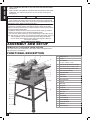
ASSEMBLY AND SETUP
REMOVE ALL THE PARTS FROM THE BOX
Your table saw is fully assembled in the carton with the exception of the
stand and some accessories
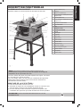
FUNCTIONAL DESCRIPTION
.
A Rubber foot (4 x)
B Leg (4x)
C Stand stretchers
(2 x side, 1 x front & 1 x rear)
D Short hex bolt, at washer & nut (24 sets)
E Stand skirt (2 x side, 1 x front & 1 x rear)
F Long hex bolt, at washer & nut (4 sets)
G Switch with removeable key
H Handwheel handle
I Handwheel
J Cable storage
K Blade tilt lock lever
L Front rail
M Miter gauge
N Blade guard
O Riving knife
P Anti-kickback pawls
Q Table insert
R Rip fence
S 10” saw blade
T Fence lock handle
U Fence storage clip
V Blade angle inticator
W Push stick
X Blade angle scale
! WARNING !
CALIFORNIA PROPOSITION 65
This product or its power cord may contain chemicals, including lead,
known to the State of California to cause cancer and birth defects or other
reproductive harm. Wash hands after handling.
Some dust created by power sanding, sawing, grinding, drilling, and other
construction activities contain chemicals known to cause cancer, birth
defects or other reproductive harm. Some examples of these chemicals are:
─Lead from lead-based paints
─Crystalline silica from bricks and cement and other masonry products
─Arsenic and chromium from chemically-treated lumber
Your risk from these exposures varies, depending on how often you do
this type of work. To reduce your exposure to these chemicals, work in a
well ventilated area, and work with approved safety equipment,
such as those dust masks that are specially designed to lter out
microscopic particles.
WEAR PROTECTIVE GEAR.

ENGLISH
7
170807
STAND ASSEMBLY
Assemble the stand, following the photo in functional description and the
schematic drawing.
NOTE: The upper crossbars (skirt) of the stand have the locating holes
along the top edge for mounting the saw itself.
These holes must be positioned to the top of the stand. The lower cross
bars (stretchers) do not have these holes.
During assembly, ensure all locking washers are used in the correct
position and that all connecting nuts and bolts are securely tightened.
MOUNTING THE TABLE SAW
1. Lay the table saw top-down on the oor.
2. Add the completely-assembled saw stand securing the stand to the
table saw body with the enclosed nuts bolts and locking washers.
3. Once assembled, turn the complete unit over so that it now stands on
the legs. This requires two people to avoid injury when lifting.
WARNING! Before assembly DO NOT CONNECT TO POWER
SUPPLY.
SAW ASSEMBLY
1. When assembling your machine do not connect to the power supply
until you have fully read and understood this manual. After carrying
out all checks and making any necessary adjustments check that the
machine switch is in the o position, connect to the power supply and
then switch the machine on and o quickly, this will allow you to check
for any loose blades or accessories without the machine gaining full
speed.
2. Disconnect from the power supply before attempting any adjustments.
3. During manufacturing your machine is set and calibrated to cut
accurately, however movement can occur in transit. If you nd that
your machine is not cutting accurately you can make several small
adjustments easily.
MOUNTING THE BLADE
1. Ensure the machine is disconnected from the power supply,
2. Remove the screw holding the blade locating plate in the table top,
remove the locating plate.
3. Rotate the blade height adjustment wheel to lift the motor to its highest
position.
4. Remove blade locking nut and outside blade washer
5. Fit blade ensuring blade teeth are facing forward.
6. Re-t the blade washer and locking nut using the blade lock keys
(spanners) ensuring that the blade lock nut is tight.
7. Re-t the blade locating plate with the screw.
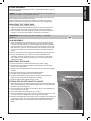
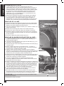
FITTING THE BLADE’S SAFETY GUARD
1. The safety guard is comprised of two assemblies pre-assembled at the
factory, the transparent guard assembly (g 2) and the riving knife/anti-
kickback pawl assembly (g 3).
2. It will be helpful now to attach the handle (H, g 1) to the handwheel (I,
g 1) at the front of the saw.
3. Be sure the blade tilt lock lever (K, g 1) is tight.
4. Remove the table insert (Q, g 1). Insert a screwdriver into the 1/2” (12
mm) round hole and lift the insert from its place in the table.
5. Raise the saw blade to its full height. Turn the handle on the handwheel
clockwise to do this. The outer surface of the handwheel changes the
blade angle and the inner wheel with handle raises and lowers the
blade.

ENGLISH
8
6. Insert the base of the riving knife into the clamp slot behind the blade as
shown (g 4). The lock lever (a, g 4) on the clamp slot should be
pointing up to allow the insertion.
7. When the riving knife is fully inserted and seated rmly, move the lock
lever 1/4 turn counter-clockwise (g 5) to clamp it there.
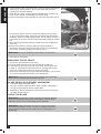
8. Place the transparent guard assembly on top of the riving knife so that
the slot in the guard’s aluminum support bar engages the two hooks
(h, g 3) along the top edge of the knife, just ahead of the attachment
bracket (b, g 3) for the anti-kickback pawls. You will have to loosen the
lock knob (k, g 2) at the back of the guard assembly aluminum support
bar.
9. When the guard assembly is rmly hooked into the slot, re-tighten the
lock knob.
10. Should it be necessary during a particular cutting operation to
temporarily remove the anti-kickback pawls from the guard assembly,
they can be removed by pulling the lock pin (p, g 3).
WARNING! Be sure to re-attach the pawls when your job is done.
11. Re-install the insert plate.
MOUNTING THE RIP FENCE
1. The fence is pre-assembled in the carton.
2. Hook the back of the fence over the rear edge of the table top.
3. Lower the front of the rip fence onto the front rail, with the fence lock
handle up. This allows it to slide along the rail. Pushing down on the
fence lock handle clamps the fence squarely into place.
4. Should it be necessary, the lock nut at the rear of the fence can be used
to increase or decrease the tension on the locking lever.
WARNING! Always ensure the rip fence is parallel to the saw blade
before use to avoid blade jam and timber kick back.
BLADE HEIGHT ADJUSTMENT HANDWHEEL
● This wheel adjusts the blade height.
● Turning it clockwise raises the blade, giving a deeper cutting depth.
● Turning counterclockwise reduces cutting depth.
● Before using, t the handwheel handle to the front of the knob to give
you more accurate control.
CHECK THE BLADE
WARNING! First time use or after changing the saw blade. With the
machine DISCONNECTED from the power supply, rotate the blade
carefully by hand to ensure that nothing fouls its operation.
WARNING! Always disconnect the tool from power source before
making any adjustments, storing, servicing, or changing accessories.
Such preventive safety measures reduce the risk of starting the tool
accidentally.

ENGLISH
9
170807
OPERATING PROCEDURES
POWER SOURCE CONNECTION
POWER REQUIREMENTS
This tool is designed to operate on a properly grounded 120 volt, 60 Hz,
single phase alternating current (AC) power source fused with a 15 amp
time delayed circuit breaker. It is recommended that a qualied electrician
verify the ACTUAL VOLTAGE at the receptacle into which the tool will be
plugged and conrm that the receptacle is properly grounded. The use of
the proper circuit size can eliminate nuisance circuit breaker tripping when
using your tool.
CAUTION: DO NOT OPERATE THIS TOOL if the ACTUAL power
source voltage is less than 105 volts AC or greater than 132 volts
AC. Contact a qualied technician if this problem exists. Improper
performance, and/or, damage to the tool will result if operated on
inadequate, or excessive power.
CONNECT TO POWER SOURCE
Consult a qualied electrician for proper installation of receptacle at the
source of power. This tool must be grounded while in use to protect the
operator from electrical shock. If you are not sure if your outlet is properly
grounded, have it checked by a qualied electrician. Make sure the tool is
turned OFF when connecting the power cord to a properly grounded 120
Volts, 60 Hz, single phase, 15 amp power source.
ON-OFF SWITCH
The power switch assembly is equipped with a safety key to help prevent
unauthorized use of the saw.
1. To provide power, connect the power cord/plug of the power switch
assembly to the nearest electrical outlet.
2. Insert the safety key into the power switch and pull up on the power
switch to provide power to the saw.
3. To shut o power to the saw, push down on the power switch and
remove the safety key.
4. Store the safety key in a safe location, out of reach of children and other
unauthorized users.
USING YOUR SAW
After unpacking, reading the instructions, attaching the machine to the
stand, and checking that all attachments are correctly installed, you can
use your saw.
WARNING! Be sure to wear appropriate protective equipment. For
your safety, remove chips, small pieces, etc. from the table top before
operation.
START UP
1. Unlock the saw from its various storage and shipping positions.
2. Check to ensure everything is correctly attached, screws are fastened,
and all adjusting keys and wrenches are removed.
3. Connect the saw to power.
4. Switch the machine on and wait until the saw blade reaches its
maximum speed.
WARNING! The blade tilt lock lever must be locked during all cuts.
MITER CUTTING / CROSS CUTTING
1. Cross cutting is an operation where the work piece is cut across the
grain, this can be either at 90 degrees or at any other required angle,
using the bevel cutting miter gauge
2. Loosen the lock knob on the miter gauge, adjust the gauge to the
required angle, and hold the work piece rmly and push through the
blade.

ENGLISH
10
BEVEL CUTTING
1. Loosen the bevel lock lever and push the hand wheel until the blade is
at the required angle of cut.
2. Lock the hand wheel at this required position.
WARNING! To avoid injury, when cross cutting or ripping ALWAYS use
the correct guide fence, NEVER try these operations free hand. Always
set the blade depth approximately 1/8” (3.5mm) above the work piece
thickness. This not only provides the safest method of cutting but also
gives the maximum number of blade teeth in the work piece at any one
time, reducing stress on the motor.
RIP CUTTING
(Cutting with the grain or length-wise)
This action must be done using the rip fence.
1. Before turning on the machine, adjust the rip fence to the required
cutting width, lock the fence into position.
2. Turn on the machine.
3. When maximum speed is reached, feed the timber into the blade
holding it rmly against the fence.
4. Always use the push stick provided, to nish the cut. NEVER reach over
the table or try nishing the cut freehand. The push stick is supplied to
ensure your safety when used correctly.
MAINTENANCE
PREVENTIVE MAINTENANCE
Keep your tool in good condition by adopting a regular maintenance
program.
WARNING! Prior to inspection or saw maintenance, turn o power
switch and disconnect plug from power source.
● Before use, examine the general condition of your tool.
● Inspect blades, switches, tool cord and extension cord for damage.
● Check for loose screws, misalignment, binding of moving parts,
improper mounting, broken parts, and any other condition that may
aect its’ safe operation.
● If abnormal noise or vibration occurs, turn the tool o immediately and
have the problem corrected before further use.
● Do not use a damaged tool.
● Never disassemble the tool or try to do any rewiring on the tool’s
electrical system.
● Keep the vents clear of dust and debris. This will help prevent possible
electrical shorts and ensure proper cooling. Use a soft brush to remove
any dust particles. Wear safety glasses to protect your eyes whilst
cleaning.
● Regularly wipe any saw dust from the fence. A buildup of dust on the
fence can prevent accurate cutting.
● If the blade has become dirty, use a blade cleaner (not included) to
clean it. Dirty blades will bind more easily, and will more often overheat
and burn the wood as it cuts. Overheated blades dull more easily.
● If the blade has become dull, replace it. Dull blades will cause
increased tear-out and ragged edges on the cuts.
● Lubricate all moving parts at regular intervals.
● Keep the tool housing and handle clean and free of oil and grease
using mild soap and a damp (not wet) cloth.
● Use only mild soap and damp cloth to clean your tool since certain
cleaning agents and solvents are harmful to plastics and other insulated
parts. Some of these harmful solvents include: gasoline, turpentine,
lacquer thinner, paint thinner, chlorinated cleaning solvents, ammonia,
and household detergents containing ammonia.

ENGLISH
11
170807
NOTE: In case of an electrical fault always turn your power tool OFF
and disconnect from the mains electric supply before attempting to
diagnose and resolve the problem.
● An authorized repair center should do any repairs, modication, or
maintenance that involve disassembling the saw.
● Any damage to the tool should be corrected at an authorized repair
center. Contact General International for all repairs.
WARNING! Never use ammable or combustible solvents around tools.
WARNING! To reduce the risk of injury, electric shock and damage to
the tool, never immerse your tool in liquid or allow liquid to ow inside the
tool.

ENGLISH
12
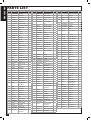
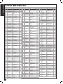
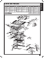
PARTS LIST
POS. PART NO. DESCRIPTION Qty.
1 TJ250GA03002 Blade guard 1
2 TJ250GA03006 Bead ange 8 2
3 GB119-86 Cylindrical pin 8 x 30 1
4 TJ250GA03007 Anti-kickback support 1
5 TJ250GA03008 Locking shaft 1
6 TJ250GA03005 Anti-kickback pawl 2
7 GB/T818 Pan head screw M5 x 45 2
8 TJ250GA03003 Guard support 1
9 TJ250GA03009 Spring 1
10 TJ250GA03004 Riving knife 1
11 TJ250GA02008 Table insert 1
12 TJ250GA01001 Table 1
13 31502030-4 Locking dog 1
14 TJ250GA01003B Slide rail 1
15 DJ250A02008A-2 Clamping block 1
16 TJ250GA04004A Fence 1
17 GB/T5783 Hexagon bolt M6 x 12 2
18 TJ250GA04002 Pull rod 1
19 RTS250K04003 Slide carriage 1
20 GB/T879.1 Spring column pin 1
21 RTS250K04006 Lock lever 1
22 RTS250K04005 Tension knob 1
23 GB/T818 Pan head screw M6 x 20 1
24 GB/T818 Pan head screw M4 x 8 1
25 RTS250K04001 Indicator 1
26 GB/T879.1 Spring column pin 1
27 31502013 Knob 1
28 GB/T96.2 Flat washer 6 1
29 DJ250B02007-1 Miter gauge 1
30 GB/T819.1 Flat head screw M4 x 8 2
31 RTS250K04007 Miter gauge plate 1
32 GB/T818 Pan head screw M4 x 8 1
33 GB/T97.1 Flat washer 4 1
34 DJ250B02007-3 Indicator 1
35 RTS250K04016B Miter gauge bar 1
36 GB/T70.1 Slotted cheese-head
screw M8 x 14
2
37 GB/T93 Spring washer 8 4
38 GB/T96.2 Flat washer 8 1
39 TJ250B02012A Driven pulley 1
40 6PJ251 Poly V-belt 1
41 GB/T894.1 External circlip 17 1
42 HC13120F-T Motor 1
43 GB/T276 Bearing 6003-2Z 2
44 TJ250B03024 Spacer 1
45 GB/T893.1 External circlip 35 1
46 GB/T6170 Hex nut M4 3
47 TJ250B02015A Shaft assembly 1
48 RTS250H03030 Live shaft assembly 1
49 GB/T70.1 Slotted cheese-head
screw M5 x 12
4
POS. PART NO. DESCRIPTION Qty.
50 RTS250H02003 Riving knife plate 1
51 GB/T889.1 Self-locking nut M8 4
52 TJ250GA02005 Riving knife support 1
53 TJ250GA02007 Handle 4
54 TJ250GA02006 Riving knife pressing
plate
1
55 GB/T818 Pan head screw M3 x 4 2
56 GB/T5783 Hexagon bolt M8 x 40 1
57 GB/T894.1 External circlip 45 1
58 TJ250E01011B Blade 1
59 TJ25002006B Flange 1
60 GB/T6173 Nut M16 x 1.5 1
61 GB/T80 Set screw M6 x 8 1
62 TJ250B02013A Drive pulley 1
63 RTS250G06015A Bolt 2
64 GB/T1972 Spring washer 2
65 GB/T889.1 Self locking nut M6 2
66 RTS250G03034 Motor bracket 1
67 RTS250G03009 Gear 1
68 GB/T14 Square neck bolt M6
x 14
1
69 RTS250G03032 Leading truck 1
70 GB/T818 Pan head screw M5 x 14 2
71 TJ250GA02004 Tie plate 1
72 RTS250G06019 Protective plate 1
73 RTS250H03045 Lever 1
74 GB/T818 Pan head screw M5 x 14 1
75 RTS250G06020 Rotating plate 1
76 GB/T818 Pan head screw M5 x 14 1
77 GB/T889.1/1 Self-locking nut M5 4
78 GB/T1972 Spring washer 2
79 GB/T6172.1 Hex nut M8 4
80 TJ25003013B Screw shaft 1
81 GB/T819.1 Flat head screw M4 x 10 6
82 GB/T97.1 Flat washer 8 4
83 GB/T6170 Hex nut M8 4
84 GB/T819.1 Flat head screw M8 x 25 2
85 GB/T70.1 Slotted cheese-head
screw M8 x 25
2
86 GB/T96.2 Flat washer 6 1
87 31503009 Handle 1
88 RTS250G06003 Hand wheel 1
89 GB/T1972 Belleville spring washer 4
90 RTS250G06004 Rocker arm 1
91 RTS250G06022 Hand wheel knob 1
92 RTS250G06025/ Tube 1
93 GB/T70.1 Slotted cheese-head
screw M6 x 45
1
94 RTS250G06023 Knob cover 1
95 GB/T819.1 Flat head screw M4 x 10 3
96 RTS250G03003 Cable support 2
POS. PART NO. DESCRIPTION Qty.
97 Cable 1
98 6P-4 Cable gland 3
99 RTS250G03001A Housing 1
100 GB/T845 Tapping screw ST4.2
x 16
4
101 RTS250K05002 Junction box 1
102 TJ250GA04009 Earth plate 1
103 RTS250G05001 Switch plate 1
104 HY18-4P Switch 1
105 GB/T846 Tapping screw ST3.5
x 13
2
106 GB/T97.1 Flat washer 6 46
107 GB/T5783 Hexagon bolt M6 x 30 4
108 GB/T5783 Hexagon bolt M6 x 35 1
109 RTS250G03012 Blade support 1
110 RTS250G06009 Retention knob 1
111 GB/T5783 Hexagon bolt M6 x 50 2
112 TJ25003023 Back clip 1
113 TJ25003022 Front clip 1
114 TJ315B06012A Push stick 1
115 TJ250B06020 Wrench 2
116 RTS250G06013 Bottom plate 1
117 GB/T845 Tapping screw ST3.5
x 13
6
118 TJ250W06002 Side skirt 2
119 TJ250W06004 Side stretcher 2
120 RTS250M03001 Leg 4
121 DT/01-017 Foot pad 4
122 TJ250W06003 Front and rear stretcher 2
123 TJ250W06001 Front and rear skirt 2
124 GB/T119.1 Cylindrical pin 5 x 22 2
125 GB/T5783 Hexagon bolt M6 x 12 46
126 GB/T6170 Hex nut M6 46
127 DJ250A02008A-3 Spring 1
128 GB/T93 Spring washer 10 4
129 GB/T70.1 Slotted cheese-head
screw M10 x 20
4
130 GB/T93 Spring washer 8 4
131 RTS250G06006 Angle pointer 1
132 TJ250W01100 Front plate 1
133 GB/T879.1/ Cylindrical pin 3 x 20 1
134 RTS250G03025 Threaded rod 1
135 RTS250G03010 Gear rack 1
136 RTS250G03002 Base guard 1
137 GB/T896 Split washer 6 1
138 TJ250GA03010 Spring 1
139 B/D4603011-3 Knob 1
140 GB/T39 Square nut M5 1
141 GB/T96.2 Flat washer 5 2

ENGLISH
13
170807
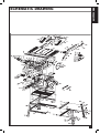
SCHEMATIC DRAWING
SCHEMATIC DRAWING

ENGLISH
14

TS4001 man v.170807
MANUEL D’INSTRUCTIONS ET D’ASSEMBLAGE
Modèle #
General International Power Products, LLC
6243 Industrial Parkway
Whitehouse, OH 43571 USA
General International Power Products Ltd.
8360 Champ d’Eau
Montréal, QC H1P 1Y3 Canada
site Web : www.gipowerproducts.com
CARACTÉRISTIQUES
● Puissant moteur
de 13 ampères
● Table en fonte d’aluminium
● Couteau diviseur
● Dispositif anti-retour
● Inclus :
● Lame de 24 dents au
carbure 10 po
● Guide à refendre
● Guide à onglets
● Poussoir
● Support en acier
SPÉCIFICATIONS
● 120 V ~ 60 Hz 13 A
● 5 700 tr/min
● Profondeur max. de coupe à
90° : 2-7/8 po (73 mm)
● Profondeur max. de coupe à
45° : 2-5/8 po (65 mm)
● Inclinaison de la lame :
0° à 45° à gauche
● Dimensions de la table :
26 po x 17-1/2 po
(660 mm x 440 mm)
● Hauteur de la table (avec
support) : 35-3/8 po (900 mm)
● Homolologué ETL
● Poids net :
44 lb (20 kg)
TS4001
Scie d’établi 10 po
3150598

FRANÇAIS
16
NOUS VOUS REMERCIONS
d’avoir choisi une machine de General International. Cette outil a été
soigneusement testée et inspectée avant de vous être expédiée, et
moyennant une utilisation et un entretien adéquats, elle vous procurera
un service able pendant de nombreuses années. An d’obtenir un
rendement optimal et une utilisation sans problème, et d’optimiser
votre investissement, veuillez prendre le temps de lire ce manuel avant
d’assembler, d’installer et d’utiliser l’unité.
Ce manuel vise à vous familiariser avec l’utilisation sécuritaire, les
fonctions élémentaires et les caractéristiques de cette scie ainsi qu’avec
le réglage, l’entretien et l’identication de ses parties et composantes. Il
n’est pas conçu pour remplacer un enseignement théorique sur le travail
ni pour orir à l’utilisateur une formation en la matière. En cas de doute
concernant la sécurité d’une opération ou d’une procédure, demandez
l’aide d’une personne qualiée avant d’entamer le travail.
Une fois que vous avez lu ces instructions, conservez ce manuel aux ns
de consultation ultérieure.
GARANTIE DE
GENERAL
®
INTERNATIONAL
Toutes les composantes des machines de General
®
International sont
soigneusement inspectées durant chacune des étapes de production, et
chaque unité est inspectée en profondeur une fois l’assemblage terminé.
GARANTIE STANDARD
LIMITÉE DE 2 ANS
En raison de son engagement envers la qualité et la satisfaction du
consommateur, General
®
International accepte de réparer ou de remplacer
toute pièce qui, suite à l’examen, se révèle défectueuse quant aumatériel
et au ni d’exécution pour une période de 2 ans (24 mois) suivant la date
d’achat. Pour se prévaloir de la garantie, l’acheteur doit retourner toutes
les pièces défectueuses port payé à General
®
International.
Les réparations eectuées sans le consentement écrit de General
®
International annuleront la garantie.
CLAUSE DE NON-RESPONSABILITÉ
L’information et les caractéristiques présentées dans ce manuel se
rapportent à la machine telle qu’elle est sortie de l’usine au moment de
mettre sous presse. En raison de son souci d’amélioration constante,
General International se réserve le droit de modier des composantes, des
pièces ou des caractéristiques de la machine si cela est jugé nécessaire,
sans préavis et sans obligation d’eectuer ces modications sur les
machines déjà vendues. On prend soin de s’assurer à l’usine que les
caractéristiques et l’information présentées dans ce manuel correspondent
à la machine avec laquelle il est fourni.
Toutefois, en raison de commandes spéciales et de modications
réalisées “hors de l’usine,” une partie ou la totalité de l’information
contenue dans ce manuel peut ne pas s’appliquer à votre machine. De
plus, comme il se peut que plusieurs générations de ce modèle d'outil et
plusieurs versions de ce manuel soient en circulation, il est possible que
ce manuel ne décrive pas exactement votre machine si vous possédez
une version antérieure ou ultérieure. Si vous avez des doutes ou des
questions, veuillez communiquer avec votre détaillant ou notre ligne de
soutien technique et mentionner le numéro de modèle et de série de votre
machine an d’obtenir des éclaircissements.
DEMANDE DE RÉCLAMATION
Pour présenter une demande de réclamation en vertu de notre Garantie
Standard Limitée de 2 ans, ou en vertu de notre Garantie Limitée à Vie,
toute pièce, composante ou machinerie défectueuse doit être retournée,
port payé, à General
®
International, ou encore à un distributeur, un centre
de réparation ou tout autre emplacement situé près de chez vous et
désigné par General
®
International. Pour plus d’informations ou si vous
avez besoin d’aide pour remplir une demande de réclamation, contactez
notre département de service. USA : numéro sans frais (844) 877-5234
ou (419) 877-5234 / Canada : numéro sans frais (888) 949-1161 ou
(604) 420-2299 ou sur notre site Web : www.gipowerproducts.com.
Une copie de la preuve d’achat originale ainsi qu’une lettre (un formulaire

FRANÇAIS
17
170807
de réclamation de garantie peut vous être fourni sur demande par
General
®
International ou par un distributeur agréé) spéciant clairement le
modèle et le numéro de série de l’unité (si applicable), et faisant état de la
plainte ou du défaut présumé, doivent être jointes au produit retourné.
CONDITIONS ET EXCEPTIONS
Cette couverture ne s’applique qu’au premier acheteur. Un enregistrement
préalable de la arantie n’est pas requis. Par contre, une preuve d’achat –
soit une copie du coupon de caisse ou du reçu original, sur lequel gurent
la date et le lieu d’achat ainsi que le prix payé – doit être fournie lors de la
réclamation.
La Garantie ne couvre pas les défaillances, bris ou défauts qui, après
examen par General
®
International, sont considérés comme étant
directement ou indirectement causés par ou résultant de: une utilisation
incorrecte, un entretien inadéquat ou l’absence d’entretien, un usage
inapproprié ou abusif, la négligence, un accident, des dommages survenus
durant la manutention ou le transport, ou encore l’usure normale ou la
détérioration des pièces et composantes considérées, de façon générale,
comme étant des consommables.
Les réparations eectuées sans le consentement écrit de General
®
International annuleront toute garantie.
LISEZ TOUTES LES INSTRUCTIONS
AVANT L’UTILISATION
CONSERVEZ CES INSTRUCTIONS
Avant d’essayer de faire fonctionner votre nouvel outil, veuillez lire
les instructions au complet. Vous aurez besoin de ces instructions
pour les avertissements de sécurité, les précautions, l’assemblage, le
fonctionnement, les procédures d’entretien, la liste des pièces et les
schémas des pièces. Gardez votre facture avec ces instructions. Écrivez
votre numéro de facture à l’intérieur de la page couverture. Gardez les
instructions ainsi que la facture dans un endroit sûr et sec pour référence
future.
LES AVERTISSEMENTS, LES PRÉCAUTIONS ET LES
instructions discutés dans ce manuel ne peuvent pas couvrir toutes les
conditions et les situations qui pourraient survenir. L’utilisateur se doit de
comprendre que le bon sens ainsi que la prudence sont des facteurs qui
ne peuvent être incorporés dans ce produit, mais peuvent être fournis
par l’utilisateur lui-même.
REGLES DE SÉCURITÉ ET
DIRECTIVES
L’objectif des symboles de sécurité est d’attirer votre attention sur les
risques potentiels. Les symboles de sécurité, ainsi que les explications les
accompagnant, nécessitent votre attention et votre compréhension. Les
avertissements de sécurité n’éliminent pas d’eux-mêmes tous les dangers.
Les instructions ou les avertissements qu’ils donnent ne sont pas un
remplacement aux mesures de prévention d’accident appropriées.
DANGER!
Indique une situation à risque imminent, laquelle si elle n’est
pas évitée, causera de sérieuses blessures ou la mort
.
AVERTISSEMENT!
Indique une situation à risque imminent, laquelle si
elle n’est pas évitée, pourrait causer de sérieuses blessures ou la mort.
ATTENTION: Indique une situation à risque imminent, laquelle si elle
n’est pas évitée, peut causer des blessures mineures ou des blessures
légères. Il peut aussi être utile de demeurer alerte au sujet des pratiques
non sécuritaires qui pourraient causer des dommages à la propriété.

FRANÇAIS
18
AVERTISSEMENTS
1. CONSERVEZ L’AIRE DE TRAVAIL PROPRE. Le désordre invite les
blessures.
2. SOYEZ CONSCIENT DE VOTRE ENVIRONNEMENT DE TRAVAIL. Ne
pas utiliser les outils motorisés dans des endroits humides, mouillés ou
insusamment éclairés. Ne pas exposer vos outils à la pluie. Conservez
l’aire de travail bien éclairée. Ne pas utiliser les outils en présence de
gaz ou de liquides inammables.
3. CONSERVEZ LES ENFANTS ET LES SPECTATEURS À L’ÉCART.
Tous les enfants doivent être tenus à l’écart de l’aire de travail. Ne
leur permettez pas de toucher les machines, les outils ou les cordes
de rallonge. Les visiteurs peuvent causer une distraction et on doit les
protéger contre les blessures corporelles.
4. LES OUTILS MIS À LA TERRE DOIVENT ÊTRE BRANCHÉS DANS
UNE PRISE QUI ELLE-MÊME A ÉTÉ INSTALLÉE ET MISE À LA
TERRE ADÉQUATEMENT. Si l’outil avait un problème électrique, la
mise à la terre ore un cheminement de faible résistance transportant
l’électricité à la mise à la terre loin de l’opérateur. Ne jamais enlever la
broche de mise à la terre ou modier la che. En cas de doute quant
à l’installation appropriée de la mise à la terre, consultez avec un
électricien qualié.
5. PRÉVENEZ LES CHOCS ÉLECTRIQUES. Éviter le contact de votre
corps avec les surfaces mises à terre : tuyaux, radiateurs, cuisinières
et réfrigérateurs. Si votre corps est mis à la terre, le risque de choc
électrique est augmenté. Si vous eectuez des travaux dans les
secteurs où des ls électriques sous tension pourraient être touchés,
tentez de déterminer s’il y a un risque de choc électrique. Mais en toute
circonstance, NE PAS TOUCHER AUCUNE PARTIE MÉTALLIQUE
DE L’OUTIL durant son usage. Toujours tenir l’outil par la poignée en
plastique pour prévenir les chocs électriques en cas de contact avec un
l sous tension.
6. NE PAS ABUSER LE CORDON. Ne jamais transporter votre outil par le
cordon ou tirer sur le cordon pour le débrancher. Protégez le cordon des
sources potentielles de dommage : La chaleur, l’huile et les solvants,
les rebords aiguisés ou les pièces mobiles. Remplacez les cordons
endommagés immédiatement.
7. POUR LE TRAVAIL À L’EXTÉRIEUR, TOUJOURS UTILISER
UNE CORDE DE RALLONGE HOMOLOGUÉE POUR L’USAGE
À L’EXTÉRIEUR. Une corde de rallonge homologuée pour usage à
l’extérieur doit porter la marque « W-A » ou « W ».
8. NE PAS EXPOSER LES OUTILS ÉLECTRIQUES À L’HUMIDITÉ. La
pluie ou les conditions humides peuvent causer l’inltration d’eau dans
l’outil et il peut alors y avoir un risque de choc électrique.
9. ASSUREZ-VOUS QUE LA CORDE DE RALLONGE QUE VOUS
UTILISEZ EST DE CALIBRE SUFFISANT POUR SA LONGUEUR.
Longueur totale de la rallonge
Calibre en
ampères
Pieds Mètres Pieds Mètres Pieds Mètres Pieds Mètres
25 8 50 15 100 30 125 40
3-10 A 18 ga. 16 ga. 14 ga. 14 ga.
10.1 - 12 A 16 ga. 16 ga. 14 ga. 14 ga.
12.1 - 16 A 14 ga. 12 ga. Non recommandé
Utilisez seulement des rallonges homologuées UL ou CSA
10. REMISEZ L’ÉQUIPEMENT QUI N’EST PAS UTILISÉ. REMISEZ
L’ÉQUIPEMENT dans un endroit sec pour empêcher la rouille.
L’équipement devrait aussi être remisé dans un endroit haut ou sous
clé, hors d’atteinte de la portée des enfants.
11. NE PAS FORCER L’OUTIL. Il fera un meilleur travail, de manière plus
sécuritaire, au rythme pour lequel il est conçu.
12. UTILISEZ L’OUTIL APPROPRIÉ. Ne pas forcer un petit outil ou un
accessoire à faire le travail d’un outil industriel plus gros. Ne pas utiliser
un outil à une n pour laquelle il n’a pas été conçu.
!

FRANÇAIS
19
170807
13. HABILLEZ-VOUS DE MANIÈRE APPROPRIÉE. Ne pas porter
de vêtement ample ou de bijoux. Ils peuvent être attrapés par les
pièces mobiles. Des gants de protection à l’épreuve de la conductivité
électrique et des souliers antidérapants sont recommandés durant le
travail. Portez un couvre-tête de protection pour recouvrir les cheveux
longs et prévenir les emmêlements.
14. PROTÉGEZ VOS YEUX. Utilisez un masque qui recouvre le visage
tout entier si le travail que vous eectuez produit de la limaille
métallique, de la poussière ou des éclats de bois. Des lunettes de
sécurité sont appropriées dans les autres situations. Portez un masque
à poussière propre si le travail implique la création d’une quantité
appréciable de poussière ne ou à gros grains.
15. FIXEZ SOLIDEMENT LA PIÈCE DE TRAVAIL. Utilisez des pinces ou
un étau pour tenir la pièce de travail. C’est beaucoup plus sécuritaire
que l’usage de vos mains et ceci libère vos deux mains pour contrôler
l’outil.
16. NE PAS VOUS ÉTIREZ. Conservez vos pieds sur le sol et maintenez
votre équilibre en tout temps. Ne vous avancez pas au-dessus ou à
travers les machines qui sont en mode de fonctionnement.
17. MAINTENEZ L’OUTIL EN BON ÉTAT. Conservez l’outil elé et propre
pour une meilleure performance et plus de sécurité. Observez les
instructions pour la lubrication et la performance sécuritaire. Respectez
les directives de lubrication et de changement des accessoires.
Conservez les poignées propres, sèches et libres d’huile et de graisse.
18. ÉVITEZ LA MISE EN MARCHE ACCIDENTELLE. Assurez-vous que
l’interrupteur est à la position « ARRÊT » avant de brancher l’outil.
19. TOUJOURS VÉRIFIEZ ET RETIREZ LES CLÉS DE RÉGLAGE ET
LES CLÉS ANGLAISES AVANT DE METTRE L’OUTIL EN MARCHE.
Laissez en place, ces pièces peuvent se détacher de la pièce qui tourne
et causer des blessures.
20. NE PAS UTILISER L’OUTIL SI L’INTERRUPTEUR « EN MARCHE
/ ARRÊT » NE FONCTIONNE PAS CORRECTEMENT. Faire réparer
votre outil avant de l’utiliser.
21. DÉBRANCHEZ L’OUTIL DE LA PRISE DE COURANT AVANT DE
FAIRE LES RÉGLAGES. Les changements de pièce ou d’accessoire
peuvent être dangereux si l’outil peut être activé accidentellement.
22. SOYEZ ALERTE. SURVEILLEZ VOS MOUVEMENTS ET UTILISEZ
LE SENS COMMUN. N’utilisez pas un outil quand vous êtes fatigué.
23. EXAMINEZ POUR DES PIÈCES ENDOMMAGÉES. Avant d’utiliser
cet outil, toute pièce qui est endommagée devrait être soigneusement
examinée pour s’assurer qu’elle fonctionnera adéquatement et qu’elle
remplira sa fonction. Vériez pour l’alignement et le coincement des
pièces mobiles, le bris des pièces, les montures et toutes autres
conditions qui pourraient aecter son fonctionnement. Examinez les vis
et resserrez celles qui sont relâchées. Toute pièce qui est endommagée
devrait être correctement réparée ou remplacée par le centre de service
autorisé, sauf si autrement indiqué ailleurs dans le manuel
24. MAINTENEZ VOTRE LAME AFFÛTÉS POUR ASSURER MOINS DE
STRESS AU MOTEUR.
25. PIÈCES DE RECHANGE. Pour le service, n’utilisez que des pièces de
rechange identiques seulement.
26. SERVICE ET RÉPARATION DOIVENT ÊTRE EFFECTUÉS PAR DES
TECHNICIENS QUALIFIÉS À UN CENTRE DE SERVICE AUTORISÉ.
Des outils qui ne sont pas réparés adéquatement peuvent causés un
choc ou des blessures graves.

FRANÇAIS
20
MESURES DE SÉCURITÉ
SPÉCIFIQUES POUR
LA SCIE À ÉTABLIE
● Bois seulement. La scie a été conçue pour couper le bois seulement.
● Les lames de scie endommagées ou voilées ne devraient pas être
utilisées. Elles sont déséquilibrées et peuvent donc endommager la
scie ou causer des blessures corporelles.
● Utilisez la scie seulement si le protecteur est en place. Le protecteur
protège l’utilisateur contre les copeaux de sciage et des pièces brisées
de la lame qui peuvent être projetées suite à un bris lors de l’utilisation.
● Remplacez plaques de coupe de la table s’il est usé. Une usure
excessive augmente la possibilité de blessures causées par le débris
projeté. Lorsque vous devez régler la scie à un nouvel angle, vériez
que la scie ne coupera pas dans l’insert ni toute autre partie de la scie
à cause d’un mauvais alignement.
● Utilisez toujours la clé pour lame pour serrer la lame sur l’arbre.
● Connectez votre scie à établi à un système de dépoussiérage, si
possible. Sinon, utilisez le sac à poussière fourni avec l’outil et videz-le
régulièrement.
● Utilisez une lame de scie qui convient au travail à exécuter et à la
matière à couper.
● Ne pas mettre l’outil en marche si la lame est en contact avec le
matériau à couper. Le mouvement de la lame peut faire sauter le pièce
d’ouvrage brusquement et pourrait causer des blessures
.
ASSEMBLAGE
RETIREZ TOUTES LES PIÈCES DE LA BOÎTE
Votre scie à établi est complètement assemblée dans la boîte, sauf le
support et quelques accessoires.
! AVERTISSEMENT !
PROPOSITION 65 DE CALIFORNIE
Ce produit ou son cordon d’alimentation peuvent contenir des produits
chimiques, dont du plomb, reconnu par l’état de Californie pour provoquer
des cancers et des malformations congénitales ou d’autres problèmes de
reproduction. Se laver les mains après manipulation.
Certaines poussières créées par l’utilisation d’outils électriques tels que
sableuse, scie, meule et autre activité de construction peuvent contenir
des produits chimiques pouvant causer le cancer ou des malformations à
la naissance ainsi que des torts au système reproducteur.
Certains exemples de ses produits chimiques sont :
─ le plomb des peintures à base de plomb,
─ la silice cristallisée provenant des briques et du ciment ainsi que
d’autres produits de maçonnerie et
─ l’arsenic et le chrome du bois de construction traité chimiquement.
Vos risques d’exposition varient selon la fréquence à laquelle vous
eectuez ce type de travail. Pour réduire votre exposition à ces produits
chimiques, travaillez dans un endroit bien ventilé et travaillez avec des
équipements de sécurité approuvés, tels que les masques antipoussiéres
spécialement conçus pour ltrer les particules microscopiques.
PORTEZ ÉQUIPEMENT DE PROTECTION
La page est en cours de chargement...
La page est en cours de chargement...
La page est en cours de chargement...
La page est en cours de chargement...
La page est en cours de chargement...
La page est en cours de chargement...
La page est en cours de chargement...
La page est en cours de chargement...
-
 1
1
-
 2
2
-
 3
3
-
 4
4
-
 5
5
-
 6
6
-
 7
7
-
 8
8
-
 9
9
-
 10
10
-
 11
11
-
 12
12
-
 13
13
-
 14
14
-
 15
15
-
 16
16
-
 17
17
-
 18
18
-
 19
19
-
 20
20
-
 21
21
-
 22
22
-
 23
23
-
 24
24
-
 25
25
-
 26
26
-
 27
27
-
 28
28


General International TS4001 Manuel utilisateur
- Taper
- Manuel utilisateur
dans d''autres langues
Documents connexes
-
General International TS4001 Manuel utilisateur
-
-
-
-
-
-
Autres documents
-
 T'nB ACDI032978 Fiche technique
-
Ryobi RTS12 Le manuel du propriétaire
-
-
RIDGID R45171 Mode d'emploi
-
-
-
-
-
-
DeWalt D27400 Manuel utilisateur
