Panasonic EY7541 Manuel utilisateur
- Catégorie
- Perceuses mixtes sans fil
- Taper
- Manuel utilisateur
Ce manuel convient également à

Model No: EY7541
IMPORTANT
This manual contains safety information. Read manual completely before first using this product and save this
manual for future use.
IMPORTANT
Ce mode d’emploi contient des informations sur la sécurité. Lisez-le en entier avant d’utiliser le produit et
conservez-le pour référence.
IMPORTANTE
Este manual contiene información de seguridad. Lea completamente este manual antes de utilizar por primera
vez este producto, y guárdelo para poder consultarlo en el futuro.
Cordless Impact Wrench
Perceuse à impact sans l
Destornillador de impacto inalámbrico
Operating Instructions
Instructions d’utilisation
Manual de instrucciones
EY7541(UL).indb 1 2007/01/16 9:31:54

-
2
-
Index/Index/Indice
English: Page 3 Français: Page 15 Español: Página 29
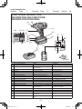
FUNCTIONAL DESCRIPTION
DESCRIPTION DES FONCTIONS
DESCRIPCIÓN FUNCIONAL
Ni-MH
Ni-Cd
(Q)
(S)
(T)
(F)
(F)
(O)
(N)(M)
(H)
(A)
(B)
(C)
(D)
(E)
(G)
(K)
(P)
(I)
(J)
(L)
(R)
(A) Square drive (ball detent)
Mandrin
Portabroca
(B) Nose protector Protection du bec Protector del morro
(C) Forward/Reverse lever Levier d’inversion marche avant/
marche arrière
Palanca de avance/marcha atrás
(D) Belt hook lock lever
Levier de verrouillage du crochet de ceinture
Palanca de bloqueo del gancho de cinturón
(E) Belt hook Crochet de ceinture Gancho del cinturón
(F) Alignment marks Marques d’alignement Marcas de alineación
(G) Battery pack release button
Bouton de libération de batterie autonome
Botón de liberación de batería
(H) Battery pack (EY9L40) Batterie autonome (EY9L40) Batería (EY9L40)
(I) LED light Lumière DEL Luz indicadora
(J) Control panel Panneau de commande Panel de control
(K) LED light ON/OFF button Bouton Marche/Arrêt de la lumière DEL Botón ON/OFF de luz LED
(L) Impact power mode button
Bouton du mode de puissance de percussion
Botón de modo de potencia de impacto
(M) Impact power mode display
Afchage du mode de puissance de percussion
Indicación de modo de potencia de impacto
(N) Battery low warning lamp
Témoin d’avertissement de batterie basse
Luz de aviso de baja carga de batería
(O) Overheat warning lamp (motor/battery) Témoin d’avertissement de surchauffe
(moteur/batterie)
Luz de advertencia de sobrecalenta-
miento (motor/batería)
(P) Variable speed control trigger Gâchette de commande de vitesse
Disparador del control de velocidad variable
(Q) Battery charger (EY0L80) Chargeur de batterie (EY0L80) Cargador de batería (EY0L80)
(R) Pack cover Couvercle de la batterie autonome Cubierta de batería
(S) Ni-MH/Ni-Cd battery pack dock Poste d’accueil de la batterie autonome
Ni-MH/Ni-Cd
Enchufe de carga de batería Ni-MH/
Ni-Cd
(T) Li-ion battery pack dock Poste d’accueil de la batterie autonome
Li-ion
Enchufe de carga de batería Li-ión
EY7541(UL).indb 2 2007/01/16 9:31:55

-
3
-
I
.
GENERAL SAFETY
RULES
WARNING! Read all instructions
Failure to follow all instructions listed
below may result in electric shock, fire
and/or serious injury. The term “power
tool” in all of the warnings listed below
refers to your mains operated (corded)
power tool and battery operated
(cordless) power tool.
SAVE THESE INSTRUCTIONS
Work Area Safety
1) Keep work area clean and well lit.
Cluttered or dark areas invite accidents.
2)
Do not operate power tools in explosive
atmospheres, such as in the presence
of flammable liquids, gases or dust.
Power tools create sparks which may
ignite the dust or fumes.
3)
Keep children and bystanders away
while operating a power tool.
Distractions can cause you to lose control.
Electrical Safety
1) Power tool plugs must match the
outlet. Never modify the plug in any
way. Do not use any adapter plugs
with earthed (grounded) power tools.
Unmodified plugs and matching outlets
will reduce risk of electric shock.
2)
Avoid body contact with earthed or
grounded surfaces such as pipes,
radiators, ranges and refrigerators.
There is an increased risk of electric shock
if your body is earthed or grounded.
3) Do not expose power tools to rain or
wet conditions.
Water entering a power tool will increase
the risk of electric shock.
4)
Do not abuse the cord. Never use
the cord for carrying, pulling or
unplugging the power tool. Keep
cord away from heat, oil, sharp edges
or moving parts.
Damaged or entangled cords increase
the risk of electric shock.
5)
When operating a power tool outdoors,
use an extension cord suitable for
outdoor use.
Use of a cord suitable for outdoor use
reduces the risk of electric shock.
Personal Safety
1)
Stay alert, watch what you are doing
and use common sense when operating
a power tool. Do not use a power tool
while you are tired or under the influence
of drugs, alcohol or medication.
A moment of inattention while operating
power tools may result in personal injury.
2)
Use safety equipment. Always wear
eye protection.
Safety equipment such as dust mask,
non-skid safety shoes, hard hat, or
hearing protection used for appropriate
conditions will reduce personal injuries.
3)
Avoid accidental starting. Ensure the
switch is in the off position before
plugging in.
Carrying power tools with your finger on
the switch or plugging in the power tools
that have the switch on invites accidents.
4)
Remove any adjusting key or wrench
before turning the power tool on.
A wrench or a key left attached to a
rotating part of the power tool may result
in personal injury.
5)
Do not overreach. Keep proper
footing and balance at all times.
This enables better control of the power
tool in unexpected situations.
6)
Dress properly. Do not wear loose
clothing or jewellery. Keep your
hair, clothing and gloves away from
moving parts.
Loose clothes, jewellery or long hair can
be caught in moving parts.
7)
If devices are provided for the
connection of dust extraction and
collection facilities, ensure these are
connected and properly used.
Use of these devices can reduce dust
related hazards.
Power Tool Use and Care
1)
Do not force the power tool. Use the
correct power tool for your application.
The correct power tool will do the job
better and safer at the rate for which it
was designed.
2)
Do not use the power tool if the
switch does not turn it on and off.
Any power tool that cannot be controlled
with the switch is dangerous and must
be repaired.
3)
Disconnect the plug from the power
source and/or the battery pack from
EY7541(UL).indb 3 2007/01/16 9:31:56

-
4
-
the power tool before making any
adjustments, changing accessories,
or storing power tools.
Such preventive safety measures
reduce the risk of starting the power tool
accidentally.
4)
Store idle power tools out of the reach
of children and do not allow persons
unfamiliar with the power tool or these
instructions to operate the power tool.
Power tools are dangerous in the hands
of untrained users.
5)
Maintain power tools. Check for
misalignment or binding of moving
parts, breakage of parts and any other
condition that may affect the power
tools operation. If damaged, have the
power tool repaired before use.
Many accidents are caused by poorly
maintained power tools.
6)
Keep cutting tools sharp and clean.
Properly maintained cutting tools with
sharp cutting edges are less likely to
bind and are easier to control.
7)
Use the power tool, accessories
and tool bits etc. in accordance with
these instructions and in the manner
intended for the particular type of
power tool, taking into account the
working conditions and the work to
be performed.
Use of the power tool for operations
different from those intended could
result in a hazardous situation.
Battery Tool Use and Care
1) Ensure the switch is in the off position
before inserting battery pack.
Inserting battery pack into power tools
that have the switch on invites accidents.
2)
Recharge only with the charger
specified by the manufacturer.
A charger that is suitable for one type
of battery pack may create a risk of fire
when used with another battery pack.
3)
Use power tools only with specifically
designated battery packs.
Use of any other battery packs may
create a risk of injury and fire.
4)
When battery pack is not in use, keep it
away from other metal objects like paper
clips, coins, keys, nails, screws, or other
small metal objects that can make a
connection from one terminal to another.
Shorting the battery terminals together
may cause burns, or a fire.
5)
Under abusive conditions, liquid may
be ejected from battery; avoid contact.
If contact accidentally occurs, flush
with water. If liquid contacts eyes,
additionally seek medical help.
Liquid ejected from the battery may
cause irritation or burns.
Service
1) Have your power tool serviced by a
qualified repair person using only
identical replacement parts.
This will ensure that the safety of power
tool is maintained.
II
.
SPECIFIC SAFETY
RULES
1) Wear ear protection. Exposure to noise
can cause hearing loss.
2)
Be aware that this tool is always in an
operating condition, since it does not have
to be plugged into an electrical outlet.
3)
Hold power tools by insulated grip-
ping surfaces when performing an
operation where the cutting tool may
contact hidden wiring.
Contact with a “live” wire will make ex-
posed metal parts of the tool “live” and
shock the operator.
4) If the bit becomes jammed, immediately
turn the trigger switch off to prevent an
overload which can damage the battery
pack or motor. Use reverse motion to
loosen jammed bits.
5)
Do NOT operate the Forward/Reverse
lever when the trigger switch is on.
The battery will discharge rapidly and
damage to the unit may occur.
6)
When storing or carrying the tool, set
the Forward/Reverse lever to the center
position (switch lock).
7)
Do not strain the tool by holding the
speed control trigger halfway (speed
control mode) so that the motor stops.
The protection circuit will activate and
may prevent speed control operation. If
this happens, release the speed control
trigger and squeeze again for normal
operation.
8) Be careful not to get dust inside the
chuck.
9) Do not touch the rotating parts to avoid
injury.
EY7541(UL).indb 4 2007/01/16 9:31:56

-
5
-
10)
Do not use the tool continuously for a long
period of time. Stop using the tool from time
to time to avoid temperature rise and heat
overload of the motor.
11) Do not drop the tool.
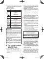
Symbol Meaning
V
Volts
Direct current
n
0
No load speed
… min
-1
Revolutions or reciprocations
per minutes
Ah
Electrical capacity of battery
pack
Read the operating instructions
before use.
For indoor use only.
WARNING!
Some dust created by power sanding, sawing,
grinding, drilling, and other construction
activities contains chemicals known to the
State of California to cause cancer, birth
defects or other reproductive harm. Some
examples of these chemicals are:
• Lead from lead-based paints
• Crystalline silica from bricks and
cement and other masonry products
• Arsenic and chromium from chemically-
treated lumber.
To reduce your exposure to these
chemicals: work in a well ventilated area,
and work with approved safety equipment,
such as dust masks that are specially
designed to filter out microscopic particles.
III
.
FOR BATTERY CHARGER
& BATTERY PACK
Important Safety Instructions
1) SAVE THESE INSTRUCTIONS -This
manual contains important safety and
operating instructions for battery charger
EY0L80.
2) Before using battery charger, read all
instructions and cautionary markings
on battery charger, battery pack, and
product using battery pack.
3) CAUTION -To reduce the risk of injury,
charge only Panasonic Battery Pack as
shown in last page.
Other types of batteries may burst
causing personal injury and damage.
4) Do not expose charger and battery pack
to rain or snow.
5) To reduce risk of damaging the electric
plug and cord, pull by plug rather than
cord when disconnecting charger.
6)
Make sure cord is located so that it
will not be stepped on, tripped over, or
otherwise subjected to damage or stress.
7) An extension cord should not be used
unless absolutely necessary.
Use of improper extension cord could
result in a risk of fire and electric shock.
If extension cord must be used, make
sure that:
a. pins on plug of extension cord are
the same number, size and shape as
those of plug on charger.
b. extension cord is properly wired and
in good electrical condition.
c. wire size is large enough for ampere
rating of charger as specified below.
RECOMMENDED MINIMUM AWG SIZE OF
EXTENSION CORDS FOR
BATTERY CHARGERS
AC Input Rating. Amperes
AWG Size of Cord
Equal to or
greater than
But less
than
Length of Cord,
Feet
25 50 100 150
0 2 18 18 18 16
8) Do not operate charger with damaged
cord or plug-replace them immediately.
9) Do not operate charger if it has received
a sharp blow, been dropped, or other-
wise damaged in any way; take it to a
qualified service personnel.
10
) Do not disassemble charger; take it
to a qualified service personnel when
service or repair is required. Incorrect
reassembly may result in a risk of
electric shock or fire.
11) To reduce the risk of electric shock,
unplug charger from outlet before
attempting any maintenance or cleaning.
12
)
The charger and battery pack are
specifically designed to work together. Do
EY7541(UL).indb 5 2007/01/16 9:31:57

-
6
-
not attempt to charge any other cordless
tool or battery pack with this charger.
13) Do not attempt to charge the battery
pack with any other charger.
14) Do not attempt to disassemble the
battery pack housing.
15) Do not store the tool and battery pack
in locations where the temperature
may reach or exceed 50°C (122
°F)
(such as a metal tool shed, or a car
in the summer), which can lead to
deterioration of the storage battery.
16) Do not charge battery pack when the
temperature is BELOW 0°C (32°F)
or ABOVE 40°C (104°F). This is very
important in order to maintain optimal
condition of the battery pack.
17) Do not incinerate the battery pack. It
can explode in a fire.
18) Avoid dangerous environment. Do not
use charger in damp or wet locations.
19) The charger is designed to operate on
standard household electrical power
only. Do not attempt to use it on any
other voltage!
20) Do not abuse cord. Never carry charger
by cord or yank it to disconnect from
outlet. Keep cord away from heat, oil
and sharp edges.
21) Charge the battery pack in a well
ventilated place, do not cover the
charger and battery pack with a cloth,
etc., while charging.
22) Use of an attachment not recommended
may result in a risk of fire, electric
shock, or personal injury.
23) Do not short the battery pack. A battery
short can cause a large current flow,
over heating and create the risk of fire
or personal injury.
24) NOTE: If the supply cord of this
appliance is damaged, it must only be
replaced by a repair shop authorized
by the manufacturer, because special
purpose tools are required.
25)
TO REDUCE THE RISK OF ELECTRIC
SHOCK, THIS APPLIANCE HAS A
POLARIZED PLUG (ONE BLADE IS
WIDER THAN THE OTHER).
This plug will fit in a polarized outlet only
one way. If the plug does not fit fully in
the outlet, reverse the plug. If it still does
not fit, contact a qualified electrician to
install the proper outlet. Do not change
the plug in any way.
IV
. ASSEMBLY
NOTE:
When attaching or removing a bit or
socket, disconnect battery pack from
tool or place the trigger switch in the
center position (switch lock).
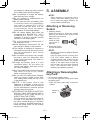
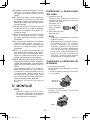
Attaching or Removing
Socket
1. Attaching Socket
Attach the socket by sliding the female
detent on the bottom of the socket to the
square drive on the body.
Make sure the
socket is firmly
connected to
the body.
2. Removing Socket
Pull out the socket.
NOTE:
Attaching or Removing Original Options
and Sockets
Keep the body above freezing point
(0°C 32°F) when attach or detach
original options and sockets to the
square drive on the body. The cushion
rubber in the square drive to push up
the ball may get hard under freezing
point. This requires extra force in
detaching and attaching sockets.
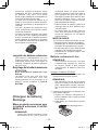
Attaching or Removing Bat-
tery Pack
1. To connect the battery pack:
Line up the alignment marks and attach
the battery pack.
•
Slide the battery pack until it locks into
position.
Alignment
marks
EY7541(UL).indb 6 2007/01/16 9:31:57

-
7
-
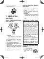
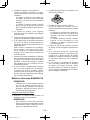
2. To remove the battery pack:
Push on the button from the front to re-
lease the battery pack.
Button
V. OPERATION
[Main Body]
Switch and Forward/Reverse
Lever Operation
Forward Reverse
Switch lock
CAUTION:
To prevent damage, do not operate
Forward/Reverse lever until the bit
comes to a complete stop.
Forward Rotation Switch
Operation
1. Push the lever for forward rotation.
2. Depress the trigger switch slightly to start
the tool slowly.
3. The speed increases with the amount of
depression of the trigger for efficient tight-
ening of screws. The brake operates and
the bit stops immediately when the trigger
is released.
4. After use, set the lever to its center posi
-
tion (switch lock).
Reverse Rotation Switch
Operation
1.
Push the lever for reverse rotation. Check
the
direction of rotation before use.
2.
Depress the trigger switch slightly to start the
tool slowly.
3. After use, set the lever to its center posi-
tion (switch lock).
CAUTION:
• To eliminate excessive temperature
increase of the tool surface, do not
operate the tool continuously using two
or more battery packs. Tool needs cool
off time before switching to another
pack.
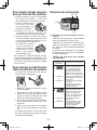
How to Use the Belt Hook
WARNING!
• Be sure to attach the belt hook securely
to the main unit with the screw firmly fas-
tened. When the belt hook is not firmly
attached to the main unit, the hook may
disconnect and the main unit may fall.
This may result in an accident or injury.
• Periodically check screw for tightness. If
found to be loose, tighten firmly.
•
Be sure to attach the belt hook firmly and
securely onto a waist belt or other belt. Pay
attention that the unit does not slip off the
belt.
This may result in an accident or injury.
• When the main unit is held by the belt
hook, avoid jumping or running with it.
Doing so may cause the hook to slip and
the main unit may fall.
This may result in an accident or injury.
• When the belt hook is not used, be sure
to return it to the storing position. The belt
hook may catch on something.
This may result in an accident or injury.
•
When the unit is hooked onto the waist belt
by the belt hook, do not attach driver bits
to the unit. A sharp edge object, such as a
drill bit, may cause injury or an accident.
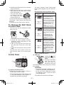
To Set the Belt Hook Angle
Position
1. Slide the belt hook lock lever 1 and hold
it to unlock the belt hook.
2
1
3
2. Pull the belt hook from
storing position 2 and
set it.
EY7541(UL).indb 7 2007/01/16 9:31:58

-
8
-
3.
Release the belt hook lock lever to
lock the
angle of belt hook.
4.
Make sure the belt hook is firmly locked.
Also make sure the belt hook is firmly
locked into position
3
.
• The belt hook cannot
be locked in this posi-
tion. Firmly lock it into
position before use.
To return the belt hook to the storing position,
Follow step 1. and 2. above, then lower the
belt hook.
To secure the lock, follow 3 and 4 above.
To Change the Belt Hook
Location Side
The belt hook can be attached to either
side of the unit.
1. Set the belt hook at storing position.
2. Loosen the screw turning it counter-
clockwise, using a flat metal or a flat
blade screw driver.
3. Take out the belt hook and insert into
the other side of the slot on the main
unit.
4. Fasten the screw firmly, turning it clock
-
wise.
The belt hook can be taken out from the
main unit only when it is at storing posi-
tion.
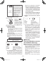
Control Panel
(1)
(2)
(4) (3)
(1) Impact Power Mode Select
Selecting the impact power among 3
modes (Soft, Medium, Hard).
Press the impact power mode button to set
it. The mode changes to hard, medium, or
soft each time the button is pressed.
The driver is preset to “hard” impact mode
setting when shipped from the manufac-
turer.
Recommended work guideline table
Impact
Power mode
Display
Recommended Application
H
Jobs requiring a high level
of torque where there is
no possibility of the bolts
or screw breaking, its top
shearing off, or the bit coming
loose. (This setting provides
maximum torque.) Suitable
applications include:
Tightening M8 and larger
bolts
Tightening long screws
during interior finishing work
0 – 2300 r.p.m.
and
0 – 3000 i.p.m.
M
Jobs requiring limited torque
where there is a possibility of
the screw breaking or its top
shearing off. (This setting limits
torque.) Suitable applications
include:
Tightening bolts with
smaller diameters (M6)
Tightening metalwork
screws when installing
fixtures
0 – 1400 r.p.m.
and
0 – 2800 i.p.m.
S
Jobs requiring limited torque
where there is a possibility
of the screw breaking, its
top shearing off, or the bit
coming loose and damaging
a nished exterior surface.
(This setting limits torque.)
Suitable applications include:
Tightening bolts smaller
than M6 that may shear
easily
Tightening screws into
molded plastic
Installing gypsum wallboard
0 – 1000 r.p.m.
and
0 – 2000 i.p.m.
* i.p.m. = Impact per minute.
(2) LED light
Pressing the button
toggles the LED light on
and off.
The light illuminates
with very low cur-
rent, and it does not
adversely affect the
performance
of the
driver during use or its bat-
tery capacity.
CAUTION:
• The built-in LED light is designed to illu-
minate the small work area temporarily.
•
Do not use it as a substitute for a regu-
lar
flashlight, since it does not have
enough brightness
.
This product has the built-in LED light.
EY7541(UL).indb 8 2007/01/16 9:32:00

-
9
-
This product is classified into
“
Class 1 LED
Product
”
to EN 60825-1
Class 1 LED Product
Caution : DO NOT STARE INTO BEAM.
(3) Overheat warning lamp
Off (normal
operation)
Flashing: Overheat
Indicates operation has
been halted due to motor
or battery overheating.
The overheating protection feature halts
driver operation to protect the motor and
battery pack in the event of overheating.
The overheat warning lamp on the control
panel flashes when this feature is active.
• If the overheating protection feature acti-
vates, allow the driver to cool thoroughly
(at least 30 minutes). The driver is ready
for use when the overheat warning lamp
goes out.
• Avoid using the driver in a way that
causes the overheating protection fea-
ture to activate repeatedly.
(4) Battery low warning lamp
Off (normal
operation)
Flashing (No charge)
Battery protection
feature active
Excessive (complete) discharging of Li-
ion batteries shortens their service life
dramatically. The driver includes a battery
protection feature designed to prevent
excessive discharging of the battery pack.
• The battery protection feature activates
immediately before the battery loses its
charge, causing the battery low warning
lamp to flash.
• If you notice the battery low warning
lamp flashing, charge the battery pack
immediately.
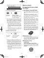
[Battery Pack]
For Appropriate Use of Bat-
tery Pack
Li-ion Battery Pack (EY9L40)
• For optimum battery life, store the Li-ion
battery pack following use without charg-
ing it.
• The ambient temperature range is
between 0°C (32°F) and 40°C (104°F).
If the battery pack is used when the bat-
tery temperature is below 0°C (32°F), the
tool may fail to function properly.
• When battery pack is not in use, keep it
away from other metal objects like: paper
clips, coins, keys, nails, screws, or other
small metal objects that can make a con-
nection from one terminal to another.
Shorting the battery terminals together
may cause sparks, burns or a fire.
• When operating the battery pack, make
sure the work place is well ventilated.
• When the battery pack is removed from the
main body of the tool, replace the battery
pack cover immediately in order to prevent
dust or dirt from contaminating the battery
terminals and causing a short circuit.
Battery Pack Life
The rechargeable batteries have a lim-
ited life. If the operation time becomes
extremely short after recharging, replace
the battery pack with a new one.
Battery Recycling
ATTENTION:
FOR Li-ion Battery Pack, EY9L40
A Li-ion battery that is recyclable powers the
product you have purchased. Please call 1-800-
8-BATTERY for information on how to recycle
this battery.
EY7541(UL).indb 9 2007/01/16 9:32:01

-
10
-
[Battery Charger]
Charging
Common Cautions for the Li-
ion/Ni-MH/Ni-Cd Battery Pack
NOTE:
• When charging a cool battery pack
(below 0°C (32°F)) in a warm place,
leave the battery pack at the place and
wait for more than one hour to warm up
the battery to the level of the ambient
temperature. Otherwise battery pack
may not be fully charged.
•
Cool down the charger when charging
more than two battery packs consecutively.
• Do not insert your fingers into contact
hole, when holding charger or any other
occasions.
CAUTION:
To prevent the risk of fire or damage to
the battery charger.
• Do not use power source from an
engine generator.
• Do not cover vent holes on the charger
and the battery pack.
• Unplug the charger when not in use.
Li-ion Battery Pack
NOTE:
Your battery pack is not fully charged at
the time of purchase. Be sure to charge
the battery before use.
Battery charger (EY0L80)
1. Plug the charger into the AC outlet.
NOTE:
Sparks may be produced when the plug
is inserted into the AC power supply, but
this is not a problem in terms of safety.
2.
Insert the battery pack firmly into the charger.
1 Line up the alignment marks and place the
battery onto the dock on the charger.
2 Slide forward in the direction of the arrow.
Alignment marks
3. During charging, the charging lamp will be
lit.
When charging is completed, an internal
electronic switch will automatically be trig-
gered to prevent overcharging.
• Charging will not start if the battery
pack is warm (for example, immediately
after heavy-duty operation).
The orange standby lamp will be flash
-
ing until the battery cools down.
Charging will then begin automatically.
4.
The charge lamp (green) will flash slowly
once the battery is approximately 80%
charged.
5.
When charging is completed, the charging
lamp will start flashing quickly in green color.
6. If the temperature of the battery pack is
0°C or less, charging takes longer to fully
charge the battery pack than the standard
charging time.
Even when the battery is fully charged, it
will have approximately 50% of the power
of a fully charged battery at normal operat-
ing temperature.
7.
If the power lamp does not light immediately
after the charger is plugged in, or if after the
standard charging time the charging lamp
does not flash quickly in green, consult an
authorized dealer.
8. If a fully charged battery pack is inserted
into the charger again, the charging lamp
lights up. After several minutes, the charg-
ing lamp may flash quickly to indicate the
charging is completed.
Ni-MH/Ni-Cd Battery Pack
NOTE:
When you charge the battery pack for
the first time, or after prolonged stor-
age, charge it for about 24 hours to
bring the battery up to full capacity.
Battery charger (EY0L80)
1. Plug the charger into the AC outlet.
NOTE:
Sparks may be produced when the plug
is inserted into the AC power supply, but
this is not a problem in terms of safety.
2.
Insert the battery pack firmly into the charger.
3.
During charging, the charging lamp will be
lit.
EY7541(UL).indb 10 2007/01/16 9:32:02

-
11
-
When charging is completed, an internal
electronic switch will automatically be trig-
gered to prevent overcharging.
• Charging will not start if the battery
pack is warm (for example, immediately
after heavy-duty operation).
The orange standby lamp will be
flashing until the battery cools down.
Charging will then begin automatically.
4.
When charging is completed, the charging
lamp will start flashing quickly in green color.
5.
If the charging lamp does not light imme-
diately after the charger is plugged in, or if
after the standard charging time the charg-
ing lamp does not flash quickly in green,
consult an authorized dealer.
6. If a fully charged battery pack is inserted
into the charger again, the charging lamp
lights up. After several minutes, the charg-
ing lamp may flash quickly to indicate the
charging is completed.
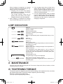
LAMP INDICATIONS
Green Lit
Charger is plugged into the AC outlet.
Ready to charge.
Green Flashing Quickly
Charging is completed. (Full charge.)
Green Flashing
Battery is approximately 80% charged (Usable charge. Li-ion
only).
Green Lit
Now charging
Orange Lit
Battery pack is cool.
The battery pack is being charged slowly to reduce the load on
the battery. (Li-ion only)
Orange Flashing
Battery pack is warm. Charging will begin when temperature of
battery pack drops.
If the temperature of the battery pack is −10°C or less, the
charging status lamp (orange) will also start ashing. Charg-
ing will begin when the temperature of the battery pack goes
up (Li-ion only).
Charging Status Lamp
Left: green Right: orange will be displayed.
Both Orange and Green Flashing Quickly
Charging is not possible. Clogged with dust or malfunction of
the battery pack.
VI
. MAINTENANCE
Use only a dry, soft cloth for wiping the unit. Do not use a damp cloth, thinner, benzine, or other
volatile solvents for cleaning.
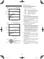
VII
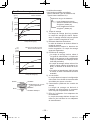
. TIGHTENING TORQUE
The power required for tightening a bolt will vary, according to bolt material and size, as well as
the material being bolted. Choose the length of tightening time accordingly.
Reference values are provided below.
(They may vary according to tightening conditions.)
EY7541(UL).indb 11 2007/01/16 9:32:03

-
12
-
Factors Affecting Tighten-
ing Torque
The tightening torque is affected by a wide
variety of factors including the followings.
After tightening, always check the torque
with a torque wrench.
1) Voltage
When the battery pack becomes near-
ly discharged, the voltage decreases and
the tightening torque drops.
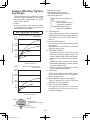
Bolt Tightening Conditions
M12
M14
M16
M10
0.0 0.5 1.0 1.5 2.0 2.5 3.0
196.0
(2000)
147.0
(1500)
98.0
(1000)
49.0
(500)
Tightening time (Sec.)
M10×35 mm M12, M14, M16 ×45 mm
Standard bolt
Tightening torque
N·m
(kgf-cm)
0.0 0.5 1.0 1.5 2.0 2.5 3.0
M12
M10
M8
196.0
(2000)
147.0
(1500)
98.0
(1000)
49.0
(500)
Tightening time (Sec.)
M8, M10×35 mm M12×45 mm
High tensile bolt
Tightening torque
N·m
(kgf-cm)
Bolt
Nut
Washer
Steel plate
thickness10 mm (3/8")
Washer
Spring washer
Tightening conditions
• The following bolts are used.
Standard bolts: Strength type 4.8
High tensile type 12.9
4.8
Explanation of the strength type
Bolt yield point
(80% of tensile strength)
32 kgf/mm
2
(45000psi)
Bolt tensile strength
40 kgf/mm
2
(56000psi)
2) Tightening time
Longer tightening time results in increased
tightening torque. Excessive tightening, how-
ever, adds no value and reduces the life of
the tool.
3) Different bolt diameters
The size of the bolt diameter affects the tight-
ening torque.
Generally, as the bolt diameter increases,
tightening torque rises.
4) Tightening conditions
Tightening torque will vary, even with the
same bolt, according to grade, length, and
torque coefficient (the fixed coefficient indi-
cated by the manufacturer upon produc-
tion).
Tightening torque will vary, even with the
same bolting material (e.g. steel), accord-
ing to the surface finish.
Torque is greatly reduced when the bolt
and nut start turning together.
5) Socket play
Torque is lowered as the six-sided configu-
ration of the socket of the wrong size is
used to tighten a bolt.
6) Switch (Variable speed control trigger)
Torque is lowered if the unit is used with
the switch not fully depressed.
7) Effect of Connecting Adaptor
The tightening torque will be lowered
through the use of a universal joint or a
connecting adaptor.
EY7541(UL).indb 12 2007/01/16 9:32:04

-
13
-
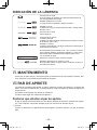
VIII
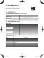
. ACCESSORIES
Use only bits suitable for size of drill’s chuck.
Use Panasonic original Optional Quick change chuck
(EY9HX110E) for maximum performance.
IX
. APPENDIX
MAXIMUM RECOMMENDED CAPACITIES
Model
EY7541
Bolt fastening
Standard bolt: M6 – M16
High tensile bolt
: M6 – M12
Screw driving
Wood screw
3.5 – 9.5 mm (1/8" – 3/8")
Self-drilling screw
3.5 – 6 mm (1/8" – 1/4")
X. SPECIFICATIONS
MAIN UNIT
Model EY7541
Motor 14.4 V DC
No load speed
soft mode 0 – 1000 min
-1
(rpm)
medium mode 0 – 1400 min
-1
(rpm)
hard mode 0 – 2300 min
-1
(rpm)
Maximum torque 185 N·m (1890 kgf-cm, 1640 in-lbs)
Impact per minute
soft mode 0 – 2000 min
-1
(ipm)
medium mode 0 – 2800 min
-1
(ipm)
hard mode 0 – 3000 min
-1
(ipm)
Overall length 167 mm (6-9/16")
Weight (with battery pack: EY9L40) 1.5 kg (3.3 lbs)
BATTERY PACK
Model EY9L40
Storage battery Li-ion Battery
Battery voltage 14.4 V DC (3.6 V × 4 cells)
Capacity 3 Ah
BATTERY CHARGER
Model EY0L80
Rating See the rating plate on the bottom of the charger.
Weight 0.95 kg (2.1 lbs)
(EY9HX110E)
EY7541(UL).indb 13 2007/01/16 9:32:05

-
14
-
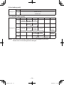
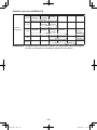
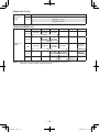
[Li-ion battery pack]
Charging time
14.4 V
3 Ah
EY9L40
Usable: 35 min.
Full: 50 min.
[Ni-Cd/Ni-MH battery pack]
Charging time
7.2 V
9.6 V 12 V 15.6 V 18 V 24 V
1.2 Ah
EY9065
EY9066
EY9080
EY9086
EY9001
20 min.
1.7 Ah
EY9180
EY9182
EY9101
EY9103
25 min.
2 Ah
EY9168 EY9188
EY9106
EY9107
EY9108
EY9136
EY9116
EY9117
30 min.
60 min.
3 Ah
EY9200 EY9230 EY9210
45 min. 90 min.
3.5 Ah
EY9201 EY9231 EY9251
55 min. 65 min.
NOTE: This chart may include models that are not available in your area.
Please refer to the latest general catalogue
.
EY7541(UL).indb 14 2007/01/16 9:32:05

-
15
-
I.
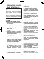
CONSIGNES DE SECU-
RITE GENERALES
AVERTISSEMENT! Veuillez lire tou-
tes les instructions.
Si les instructions détaillées ci-dessous ne sont
pas observées, cela peut entraîner une électro-
cution, un incendie et/ou des blessures graves.
Le terme “outil mécanique” utilisé dans tous les
avertissements ci-dessous se réfère aux outils
mécaniques opérés par cordons d'alimentation
et par batterie (sans l).
CONSERVEZ CES INSTRUC-
TIONS
Sécurité de la zone de travail
1) Gardez la zone de travail propre et
bien aérée.
Les endroits encombrés et sombres invi-
tent les accidents.
2)
Ne faites pas fonctionner les outils
mécaniques dans des atmosphères
explosives, comme en présence de
liquides inammables, de gaz ou de
poussière.
Les outils mécaniques génèrent des étin-
celles qui peuvent enflammer la poussiè-
re ou les vapeurs.
3)
Gardez les enfants et les spectateurs
éloignés lors du fonctionnement d’un
outil mécanique.
Les distractions peuvent en faire perdre le
contrôle.
Sécurité électrique
1) La fiche des outils mécaniques doit
correspondre aux prises secteur. Ne
modifiez la fiche sous aucun prétexte.
N’utilisez pas de fiche adaptatrice
avec les outils mécaniques mis à la
terre.
Des fiches non modifiées et des prises
secteur correspondant réduisent les
risques d’électrocution.
2)
Evitez tout contact physique avec les
surfaces mises à la terre telles que
tuyaux, radiateurs, micro-ondes et
réfrigérateurs.
Il y a un risque d’électrocution supplémen-
taire si votre corps est mis à la terre.
3) N’exposez pas les outils mécaniques à
la pluie ou à des conditions humides.
De l’eau pénétrant dans un outil mécani-
que augmente le risque d’électrocution.
4)
Ne malmenez pas le cordon. N’utilisez
jamais le cordon pour transporter,
pour tirer ou pour débrancher l’outil
mécanique. Gardez le cordon éloigné
de la chaleur, de l’huile, d’objets aux
bords coupants ou de pièces en
mouvement.
Les cordons endommagés on emmêlés
augmentent le risque d'électrocution.
5)
Lors du fonctionnement des outils méca-
niques à l
’
extérieur, utilisez une rallonge
adaptée à l
’
utilisation à l
’
extérieur.
L’utilisation d’un cordon adapté à l’utilisa-
tion à l’extérieur réduit les risques d’élec-
trocution.
Sécurité personnelle
1) Restez alerte, regardez ce que vous
faites et faites preuve de bon sens
lorsque vous utilisez un outil méca-
nique. N’utilisez pas un outil méca-
nique alors que vous êtes fatigué ou
sous les effets de drogue, d’alcool ou
de médicaments.
Un moment d’inattention pendant que
vous faites fonctionner l’outil mécanique
peut entraîner des blessures graves.
2)
Utilisez des équipements de sécurité.
Portez toujours des protection pour
vos yeux.
Des équipements de sécurité comme
masque antipoussière, chaussures
de sécurité non glissantes, casque de
protection ou protections d’oreilles,
utilisés dans des conditions appropriées
réduisent les blessures corporelles.
3)
Evitez tout démarrage accidentel.
Assurez-vous que l
’interrupteur est
en position d'arrêt avant de brancher
l’outil.
Le transport d’outils mécaniques avec le
doigt sur l’interrupteur ou le branchement
d’outils mécaniques dont l’interrupteur
est sur la position de marche invite les
accidents.
4)
Retirez toute clé d’ajustement ou
clé de serrage avant de mettre l’outil
mécanique en marche.
Une clé de serrage ou une clé d’ajuste-
ment laissée attachée à une pièce
tournante de l’outil mécanique peut
entraîner des blessures corporelles.
5)
Ne vous mettez pas en déséquilibre.
Gardez une bonne prise au sol et votre
équilibre à tout moment.
Ceci permet un meilleur contrôle de l’outil
mécanique dans des situations inatten-
dues.
EY7541(UL).indb 15 2007/01/16 9:32:06

-
16
-
6) Habillez-vous correctement. Ne portez
pas de vêtements lâches ou de bijoux.
Gardez vos cheveux, vêtements et
gants éloignés des pièces en mouve-
ment.
Des vêtements lâches, des bijoux ou
des cheveux longs peuvent se faire
prendre dans les pièces en mouvement.
7)
Si des dispositifs pour la connexion
d’appareils d’extraction et de ramas-
sage de la poussière sont fournis,
assurez-vous qu
’ils sont connectés et
correctement utilisés.
L’utilisation de ces dispositifs peut réduire
les risques concernés.
Utilisation et soins de l’outil méca-
nique
1)
Ne forcez pas l’outil mécanique. Utilisez
l’outil mécanique correct pour votre
application.
L’outil mécanique correct exécute mieux
le travail dans de meilleurs conditions
de sécurité s’il est utilisé à l’allure pour
laquelle il a été conçu.
2)
N’utilisez pas l’outil mécanique si l’inter-
rupteur ne le met pas en marche ou ne
l’arrête pas.
Tout outil mécanique qui ne peut pas
être contrôlé par son interrupteur est
dangereux et doit être réparé.
3)
Débranchez la fiche de la source d’ali-
mentation et/ou du bloc de batterie
avant d’effectuer tout ajustement, de
changer d’accessoire ou de ranger
l’outil mécanique.
De telles mesures de sécurité préventives
réduisent les risques de faire démarrer
l’outil mécanique accidentellement.
4)
Rangez les outils mécaniques inuti-
lisés hors de la portée des enfants
et ne laissez personne qui n’est pas
familiarisé avec l’outil mécanique ou
ses instructions faire fonctionner l’outil
mécanique.
Les outils mécaniques sont dangereux
dans les mains des utilisateurs manquant
d’entraînement.
5) Entretenez bien les outils mécaniques.
Vérifiez l’alignement ou l’emboîtage
des pièces en mouvement, l’intégrité
des pièces et toute autre condition
pouvant affecter le fonctionnement de
l’outil mécanique. S’il est endommagé,
faites réparer l’outil mécanique avant
de l’utiliser.
De nombreux accidents sont provoqués
par des outils mécaniques mal entre-
tenus.
6)
Maintenez les outils de coupe affûtés
et propres.
Les outils de coupe bien entretenus
avec des lames bien affûtées ont moins
de chances de gripper et sont plus
faciles à contrôler.
7)
Utilisez l’outil mécanique, les acces-
soires, les mèches, etc., conformément
à ces instructions et de la façon pour
laquelle l’outil particulier a été conçu
en tenant compte des conditions de
travail et de la tâche à exécuter.
L’utilisation de l’outil mécanique à des
fins autres que celles pour lesquelles
il a été conçu peut présenter une situa-
tion à risque.
Utilisation et soins de la batterie
de l’outil
1) Assurez-vous que l’interrupteur est
dans la position d’arrêt avant d’insérer
le bloc de batterie.
L’insertion du bloc de batterie dans un
outil mécanique dont l’interrupteur est
sur la position de marche peut provoquer
des accidents.
2) N
’effectuez la recharge qu’avec le
chargeur spécifié par le fabricant.
Un chargeur convenant à un bloc de bat-
terie peut entraîner un risque d’incendie
lorsqu’un autre bloc de batterie est
utilisé.
3)
N’utilisez les outils mécaniques
qu’avec les bloc de batterie spéciale-
ment conçus pour eux.
L’utilisation de tout autre bloc de bat-
terie peut entraîner un risque de bles-
sure et d’incendie.
4)
Lorsqu’un bloc de batterie n’est pas
utilisé, gardez-le éloigné d
’objets métal-
liques comme agrafes, pièces de mon-
naie, clés, clous, vis ou tout autre petit
objet métallique pouvant établir une
connexion entre les deux bornes.
Si les bornes de la batterie sont mises
en court-circuit, cela peut entraîner des
brûlures ou un incendie.
5)
Si elle est malmenée, du liquide peut
s’échapper de la batterie. Evitez tout
contact. Si un contact accidentel se
produit, rincez à l’eau. Si du liquide
entre en contact avec les yeux, con-
sultez un médecin.
EY7541(UL).indb 16 2007/01/16 9:32:06

-
17
-
Le liquide éjecté de la batterie peut
entraîner des irritations ou des brûlures.
Réparation
1) Faites réparer votre outil mécanique
par du personnel de réparation quali-
fié en n’utilisant que des pièces de
rechange identiques.
Ceci assure le maintien de la sécurité
de l’outil mécanique.
II
.
REGLES DE SECURITE
PARTICULIERES
1) Portez des lunettes lorsque vous uti-
lisez l’outil pendant de longues péri-
odes.
L’exposition prolongée à du bruit de
haute densité peut entraîner la perte de
l’ouïe.
2)
N’oubliez pas que cet appareil est tou-
jours prêt à fonctionner, parce qu’il ne
doit pas être branché dans une prise
électrique.
3)
Tenez l’outil par les surfaces de prise
isolées lorsque vous effectuez une
opération lors de laquelle l’outil de
coupe risque d’entrer en contact avec
des câblages cachés.
Le contact avec un fil sous tension
fera passer le courant dans les pièces
métalliques exposées et électrocutera
l’opérateur.
4) Si la mèche est coincée, mettez immé-
diatement le commutateur de la gâchette
hors tension afin de prévenir une sur-
charge pouvant endommager la batterie
autonome ou le moteur. Dégagez la
mèche en inversant le sens de rotation.
5)
NE manœuvrez PAS le levier d’inversion
marche avant - marche arrière lorsque le
commutateur principal est sur la position
de marche. La batterie se déchargerait
rapidement et la perceuse serait endom-
magée.
6)
Lorsque vous rangez ou transportez l’outil,
mettez le levier d’inversion marche avant
- marche arrière sur la position centrale
(verrouillage du commutateur).
7) Ne forcez pas l’outil en maintenant la
gâchette de contrôle de vitesse enfon-
cée à moitié (mode de contrôle de la
vitesse) de sorte que le moteur s’arrête.
Le circuit de protection s’activera et pourra
empêcher le contrôle de la vitesse. Dans
ce cas, relâchez la gâchette de contrôle
de la vitesse, puis serrez-la à nouveau
pour le fonctionnement normal
.
8) Evitez la pénétration de poussière dans
le mandrin.
9) Ne touchez pas les pièces rotatives pour
éviter toute blessure.
10) N’utilisez pas l’outil continuellement pen-
dant une longue période. Arrêtez d’utiliser
l’outil de temps en temps pour éviter une
augmentation de la température et de
surchauffer le moteur.
11) Ne laissez pas tomber l’outil.
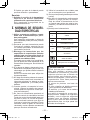
Symbole
Signication
V
Volts
Courant continu
n
0
Vitesse sans charge
… min
-1
Révolutions ou alternances
par minute
Ah
Capacité électrique de la
batterie autonome
Lisez les instructions de
fonctionnement avant
l’utilisation.
Pour l’utilisation à l’intérieur
seulement.
AVERTISSEMENT!
La poussière résultant de ponçage, sciage,
meulage, perçage à haute pression et de
toute autre activité de construction, contient
des produits chimiques réputés être cause
de cancer, de malformations congénitales ou
autres problèmes reproductifs. Ces produits
chimiques sont, par exemple :
• Le plomb contenu dans les peintures à
base de plomb
• La silice cristalline, contenue dans les
briques, le ciment et autres produits de
maçonnerie; et
• L’arsenic et le chrome provenant du
bois traité chimiquement.
Pour réduire l’exposition à ces produits
chimiques, il faut travailler dans un lieu bien
aéré et porter un équipement de sécurité
approprié tel que certains masques anti-
poussière conçus spécialement pour filtrer
les particules microscopiques.
EY7541(UL).indb 17 2007/01/16 9:32:07

-
18
-
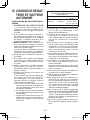
III
.
CHARGEUR DE BAT-
TERIE ET BATTERIE
AUTONOME
Instructions de sécurité impor-
tantes
1) CONSERVEZ CES INSTRUCTIONS
– La présente notice contient des in-
structions de sécurité et d’utilisation im-
portantes pour le chargeur de batterie
EY0L80.
2) Avant d
’utiliser le chargeur de batterie, li-
sez toutes les instructions et les marques
d’avertissement figurant sur le chargeur
de batterie, la batterie autonome et le
produit utilisant la batterie autonome.
3)
MISE EN GARDE
– Pour réduire le ris-
que de blessures, chargez la batterie
autonome Panasonic seulement comme
indiqué à la dernière page.
Les autres types de batteries risquent
d’exploser et de causer des blessures
corporelles et des dommages matériels.
4) N
’exposez pas le chargeur à la pluie ou
à la neige.
5) Pour réduire les risques de dommages
à la fiche et au cordon secteur, débran-
chez le chargeur en tirant la fiche et non
le cordon.
6) Veillez à acheminer le cordon de façon
que personne ne risque de le piétiner,
de trébucher dessus, d’endommager ou
d’étirer le cordon.
7) N
’utilisez une rallonge qu'en cas de né-
cessité absolue.
Si vous utilisez une rallonge inadéquate,
vous risquez de causer un incendie ou
une électrocution. Si vous devez ab-
solument utiliser une rallonge, veillez à
respecter les points suivants:
a.
Le nombre, la taille et la forme des
broches de la fiche de la rallonge doi-
vent être identiques à ceux de la fiche
du chargeur de batterie.
b.
La rallonge doit avoir des conducteurs
en bon état et être elle-même en bon
état d'utilisation.
c.
La taille des conducteurs doit être suf-
fisante pour les normes d'intensité en
ampères du chargeur, comme indiqué
ci-dessous.
TAILLE AWG MINIMUM RECOMMANDÉE DES
RALLONGES POUR CHARGEURS
DE BATTERIES
Norme d’entrée
CA
Ampères Taille AWG du
cordon
Egal ou
supérieur à
Mais
inférieur à
Longueur du
cordon, pieds
25
50 100 150
0 2 18 18 18 16
8) N’utilisez pas un chargeur dont la fiche
ou le cordon est endommagé – rem
-
placez-les immédiatement.
9) N
’utilisez pas le chargeur s’il a reçu un
choc violent, s'il a subi une chute ou s’il
a été endommagé de quelque manière
que ce soit; confiez-le à un technicien
qualifié.
10) Ne démontez pas le chargeur; si des
travaux d’entretien ou de réparation sont
nécessaires, confiez-le à un technicien
qualifié. Si vous le remontez incorrecte-
ment, vous risquez de causer une élec-
trocution ou un incendie.
11) Pour réduire le risque d’électrocution, dé-
branchez le chargeur de la prise de cou-
rant avant d’entreprendre des travaux
d’entretien ou de nettoyage.
12)
Le chargeur et la batterie autonome ont
été conçus spécifiquement pour fonc-
tionner ensemble.
Ne tentez pas de charger un autre outil à
batterie ou une autre batterie autonome
avec ce chargeur.
13) Ne tentez pas de charger la batterie au-
tonome avec un autre chargeur.
14) Ne tentez pas de démonter le logement
de la batterie autonome.
15) Ne rangez pas l’outil ou la batterie au-
tonome à des endroits où la tempéra-
ture est susceptible d'atteindre ou de dé-
passer 50°C (122°F) (par exemple dans
une remise d’outils électriques, ou dans
une voiture en été), car ceci risquerait
d'abîmer la batterie stockée.
16) Ne chargez pas la batterie autonome
lorsque la température est INFÉRIEURE
À 0°C (32°F) ou SUPÉRIEURE à 40°C
(104°F). Ceci est très important pour con-
server le bon état de fonctionnement de
la batterie autonome.
17) N’incinérez pas la batterie autonome.
Elle risquerait d'exploser dans les flam-
mes.
EY7541(UL).indb 18 2007/01/16 9:32:07

-
19
-
18) Evitez toute utilisation dans un environ-
nement dangereux. N’utilisez pas le
chargeur à un endroit humide ou mouillé.
19) Le chargeur a été conçu pour fonction-
ner uniquement sur des prises secteur
domestiques standard. Ne l’utilisez pas
sous des tensions différentes!
20) Ne manipulez pas brutalement le cor
-
don secteur. Ne transportez jamais le
chargeur en le tenant par le cordon, ou
ne le tirez pas brutalement pour le dé-
brancher de la prise. Gardez le cordon à
l’abri de la chaleur, de l’huile et de bords
coupants.
21)
Chargez la batterie autonome à un en-
droit bien ventilé; ne couvrez pas le char-
geur et la batterie autonome avec un chif-
fon, etc., pendant la charge.
22)
Si vous utilisez un accessoire non recom-
mandé, un incendie, une électrocution,
des blessures risqueraient de s’ensuivre.
23)
Ne court-circuitez pas la batterie au-
tonome. Un court-circuit de la batterie
risquerait de faire passer un courant de
forte intensité, et une surchauffe, un in-
cendie ou des blessures risqueraient de
s'ensuivre.
24) REMARQUE: Si le cordon secteur de
cet appareil est endommagé, il doit être
remplacé exclusivement dans un atelier
agréé par le fabricant, car ces travaux
exigent l’utilisation d’outils spéciaux.
25) POUR RÉDUIRE LES RISQUES
D’ÉLECTROCUTION, CET APPAREIL
EST ÉQUIPÉ D’UNE FICHE POLARI-
SÉE (UNE LAME EST PLUS LARGE
QUE L’AUTRE).
Cette fiche ne pourra être insérée que
d'une seule façon dans une prise polari-
sée. Si la fiche ne peut pas être insérée
à fond dans la prise, insérez la fiche
sens dessus dessous. Si vous ne par-
venez toujours pas à insérer la fiche, ad-
ressez-vous à un électricien qualifié pour
installer une prise de courant adéquate.
Ne modifiez la fiche en aucune façon.
IV
. MONTAGE
REMARQUE:
Lors de la fixation ou du retrait d’une
mèche ou d’une douille, déconnectez la
batterie autonome de l’outil ou mettez le
commutateur de la gâchette en position
centrale (Verrouillage du commutateur).
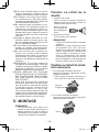
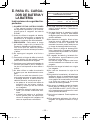
Fixation ou retrait de la
douille
1. Fixation de la douille
Fixez la douille en faisant coulisser la
détente femelle du fond de la douille sur
l’entraînement carré du corps.
Assurez-vous que
que la douille est
bien raccordée au
corps.
2. Pour retirer la douille
Tirez la douille vers l’extérieur.
REMARQUE:
Fixation et retrait des options et douilles
originales
Maintenez le corps au-dessus du point
de congélation (0ºC, 32ºF) lors de la
fixation ou du retrait des options et des
douilles originales à/de l’entraînement
carré du corps. Le coussinet en caout-
chouc de l’entraînement carré destiné
à repousser la boule peut se durcir au
point de congélation. Cela exige plus de
force pour retirer et fixer les douilles.
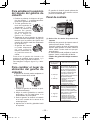
Fixation ou retrait de la bat-
terie autonome
1. Pour raccorder la batterie autonome:
Alignez les marques d’alignement et fixez
la batterie autonome.
• Faites glisser la batterie autonome jus-
qu’à ce qu’elle se verrouille en position.
Marques
d’alignement
2. Pour retirer la batterie autonome:
Appuyez sur le bouton depuis l’avant pour
libérer la batterie autonome.
Bouton
EY7541(UL).indb 19 2007/01/16 9:32:08

-
20
-
V.
FONCTIONNEMENT
[Corps principal]
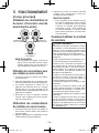
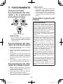
Utilisation du commutateur et
du levier d’inversion marche
avant-marche arrière
Rotation en
sens normal
Rotation en
sens inverse
Verrouillage du
commutateur
MISE EN GARDE:
Pour prévenir tout dégât, n’actionnez
pas le levier d’inversion marche avant-
marche arrière tant que la mèche n’a
pas complètement terminé de tourner.
Utilisation du commutateur pour
une rotation en sens normal
1. Poussez le levier pour obtenir une rotation
en sens normal.
2. Appuyez légèrement sur la gâchette pour
que l’outil commence à tourner lentement.
3. La vitesse augmente à mesure où la
gâchette est enfoncée pour un vissage
efficace des vis. Le frein fonctionne et la
mèche s’arrête immédiatement dès que la
gâchette est relâchée.
4. Ramenez le levier en position centrale
lorsque vous n’utilisez plus l’outil (verrouil-
lage du commutateur).
Utilisation du commutateur
de rotation en sens inverse
1.
Poussez le levier pour obtenir une rotation en
sens inverse. Avant d’utiliser l’outil, vérifiez le
sens de rotation.
2.
Appuyez légèrement sur la gâchette pour que
l’outil commence à tourner lentement.
3. Ramenez le levier en position centrale
lorsque vous n’utilisez plus l’outil (ver-
rouillage du commutateur).
MISE EN GARDE:
• Pour empêcher toute élévation exces-
sive de la température de la surface
de l'outil, n'utilisez pas l'outil de façon
continue en utilisant deux batteries
autonomes ou plus. L'outil a besoin de
se refroidir pendant un certain temps
avant d'être connecté à une autre bat-
terie autonome.
Comment utiliser le crochet
de ceinture
AVERTISSEMENT!
• Assurez-vous de bien accrocher le crochet
de ceinture à l’unité principale en serrant
bien la vis. Si le crochet de ceinture n’est
pas bien fixé à l’unité principale, le crochet
peut se décrocher et l’unité peut tomber.
Cela pourrait entraîner un accident ou des
blessures.
• Vérifiez régulièrement le serrage de la vis.
Si elle est desserrée, resserrez-la bien.
•
Assurez-vous d’accrocher fermement et
de manière sûre le crochet de ceinture sur
une ceinture de taille ou une autre ceinture.
Faites attention que l’appareil ne glisse pas
de la ceinture. Cela pourrait entraîner un
accident ou des blessures
.
• Lorsque l’unité principale est tenue par le
crochet de ceinture, évitez de sauter ou
de courir. Le crochet pourrait glisser et
l’unité principale pourrait tomber.
Cela pourrait entraîner un accident ou des
blessures.
• Lorsque le crochet de ceinture n’est pas
utilisé, assurez-vous de le remettre dans
sa position de stockage. Le crochet pour-
rait se prendre dans quelque chose.
Cela pourrait entraîner un accident ou des
blessures.
•
Lorsque l’appareil est accroché à la taille
par le crochet de ceinture, ne fixez pas de
mèche autre qu’une mèche de serrage sur
l’appareil. Un objet pointu tel qu’une mèche
de perçage pourrait entraîner un accident
ou des blessures.
EY7541(UL).indb 20 2007/01/16 9:32:08
La page est en cours de chargement...
La page est en cours de chargement...
La page est en cours de chargement...
La page est en cours de chargement...
La page est en cours de chargement...
La page est en cours de chargement...
La page est en cours de chargement...
La page est en cours de chargement...
La page est en cours de chargement...
La page est en cours de chargement...
La page est en cours de chargement...
La page est en cours de chargement...
La page est en cours de chargement...
La page est en cours de chargement...
La page est en cours de chargement...
La page est en cours de chargement...
La page est en cours de chargement...
La page est en cours de chargement...
La page est en cours de chargement...
La page est en cours de chargement...
La page est en cours de chargement...
La page est en cours de chargement...
La page est en cours de chargement...
La page est en cours de chargement...
-
 1
1
-
 2
2
-
 3
3
-
 4
4
-
 5
5
-
 6
6
-
 7
7
-
 8
8
-
 9
9
-
 10
10
-
 11
11
-
 12
12
-
 13
13
-
 14
14
-
 15
15
-
 16
16
-
 17
17
-
 18
18
-
 19
19
-
 20
20
-
 21
21
-
 22
22
-
 23
23
-
 24
24
-
 25
25
-
 26
26
-
 27
27
-
 28
28
-
 29
29
-
 30
30
-
 31
31
-
 32
32
-
 33
33
-
 34
34
-
 35
35
-
 36
36
-
 37
37
-
 38
38
-
 39
39
-
 40
40
-
 41
41
-
 42
42
-
 43
43
-
 44
44


Panasonic EY7541 Manuel utilisateur
- Catégorie
- Perceuses mixtes sans fil
- Taper
- Manuel utilisateur
- Ce manuel convient également à
dans d''autres langues
- English: Panasonic EY7541 User manual
- español: Panasonic EY7541 Manual de usuario
Documents connexes
-
Panasonic Impact Driver EY7540 Manuel utilisateur
-
Panasonic EY75A1 Operating Instructions Manual
-
-
-
-
Panasonic EY7550 Le manuel du propriétaire
-
Panasonic EY7420 Manuel utilisateur
-
-
-