
En
Fr
En
Fr
Ru
Se
Ru
Fi
Cz
Ru
Ru
Se
Ru
Fi
Cz
1-6×24 IL
Instruction manual/Mode d’emploi
Riescope/Lunette de visée

2
En
Fr
En
Fr
Ru
Se
Ru
Fi
Cz
Ru
Ru
Se
Ru
Fi
Cz
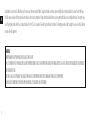
Congratulations on your choice of a Nikon riescope. Your new scope is the nest example of Nikon's rugged and durable construction and precision bright optics; important qualities for a serious shooter's riescope.
This riescope was developed for the sportsperson who mainly uses it for shooting competitions. We hope that this product will enhance your enjoyment with stable accuracy and high performance. To mount the scope,
a set of high-quality mounts which have a standard diameter of 30 mm (1.2 in.) are required. Follow the ring manufacturer's instructions for mounting procedures. After mounting the scope on your rie, follow the
procedures for reticle alignment.
WARNING:
IMPROPER MOUNTING OF YOUR NIKON SCOPE CAN CAUSE SERIOUS INJURY.
THUS IT IS IMPORTANT THAT YOUR NIKON SCOPE IS MOUNTED PROPERLY BEFORE USING. TO ENSURE PROPER MOUNTING OF YOUR NIKON SCOPE, PLEASE HAVE IT MOUNTED AND/OR CHECKED BY AN EXPERIENCED
GUNSMITH BEFORE USING.
THE USER ASSUMES ALL RESPONSIBILITY AND LIABILITY FOR HAVING THE SCOPE PROPERLY MOUNTED TO A FIREARM AND FOR USING THE SCOPE PROPERLY.
ALWAYS CHECK THE CONDITION OF YOUR SCOPE AND YOUR MOUNTING SYSTEM BEFORE USING YOUR FIREARM.

3
En
Fr
En
Fr
Ru
Se
Ru
Fi
Cz
Ru
Ru
Se
Ru
Fi
Cz
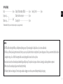
SUPPLIED ITEM(S)
Body ·················································1 piece Battery (3V Lithium battery: CR2032) ····················· 1 piece Hex key (2.0 mm) ························ 1 piece
Eyepiece cap ............ Battery-chamber cover opener ································1 piece
Objective cap...........
························ 1 pair
*
Cleaning cloth ···························································1 piece
*
Rubber band linked (This type connects the objective and eyepiece caps using a rubber band.)
Caution
(1) Do NOT look at the sun through the riescope. It will permanently damage your eye. This precaution applies to all optical devices, such as cameras and binoculars.
(2) The riescope is eectively sealed against moisture and dust. You may use your scope safely either in the rain or in dusty climates. To preserve the appearance of the scope, we recommend that it be dried and
cleaned prior to storage. Use a soft cloth for cleaning metal surfaces and use photographic lens tissue to clean the scope's lenses.
(3) Never leave the device in the sun for extended periods without the Eyepiece/Objective cap. The objective lens and eyepiece can function as a burning glass and damage the interior components.
(4) When not in use for an extended period, please remove the battery from the body.
(5) If the battery-chamber cover is damaged, or if it emits a strange sound due to dropping or some other cause, remove the battery immediately and stop using.

4
En
Fr
En
Fr
Ru
Se
Ru
Fi
Cz
Ru
Ru
Se
Ru
Fi
Cz
Caution (Lithium battery)
If handled incorrectly, the battery may rupture and leak, corroding equipment and staining clothing. Be sure to observe the following:
•
Install the battery with the + and - poles positioned correctly.
•
The battery should be removed when exhausted or during extended periods of non-use.
•
Do not short the end terminal of the battery chamber.
•
Do not carry together with keys or coins in a pocket or bag, it may short and cause overheating.
•
Do not expose the battery to water, or a ame. Never disassemble the battery.
•
Do not charge the lithium battery.
•
If liquid from a damaged battery comes into contact with clothing or skin, rinse immediately with plenty of water. If liquid from a damaged battery enters the eyes, rinse immediately with clean water, then consult a doctor.
•
When disposing of the battery, follow your local area regulations.

5
En
Fr
En
Fr
Ru
Se
Ru
Fi
Cz
Ru
Ru
Se
Ru
Fi
Cz
About controls for radio interference
•
This device complies with Part 15 of the FCC Rules. Operation is subject to the following two conditions:
(1) This device may not cause harmful interference, and
(2) This device must accept any interference received, including interference that may cause undesired operation.
•
This equipment has been tested and found to comply with the limits for a Class B digital device, pursuant to Part 15 of the FCC Rules and to EU EMC directive. These limits are designed to provide reasonable protection
against harmful interference in a residential installation. This equipment generates, uses and can radiate radio frequency energy and, if not installed and used in accordance with the instructions, may cause harmful
interference to radio communications. However, there is no guarantee that interference will not occur in a particular installation. If this equipment does cause harmful interference to radio or television reception,
which can be determined by turning the equipment o and on, the user is encouraged to try to correct the interference by one or more of the following measures:
•
Reorient or relocate the receiving antenna.
•
Increase the separation between the equipment and receiver.
•
Consult the dealer or an experienced radio/TV technician for help.
Notice for customers in Canada
CAN ICES-3(B)/NMB-3(B)

6
En
Fr
En
Fr
Ru
Se
Ru
Fi
Cz
Ru
Ru
Se
Ru
Fi
Cz
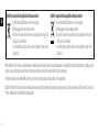
Symbol for separate collection applicable in European countries Symbol for separate collection applicable in European countries
This symbol indicates that this battery is to be collected separately.
The following apply only to users in European countries.
• Thisbatteryisdesignatedforseparatecollectionatanappropriatecollectionpoint.Do
not dispose of as household waste.
• Formoreinformation,contacttheretailerorthelocalauthoritiesinchargeofwaste
management.
This symbol indicates that this product is to be collected separately.
The following apply only to users in European countries.
• Thisproductisdesignatedforseparatecollectionatanappropriatecollectionpoint.Do
not dispose of as household waste.
• Formoreinformation,contacttheretailerorthelocalauthoritiesinchargeofwaste
management.
When setting the reticle for shooting, you should determine your standard range and then adjust the reticle based upon that target distance. For targets which vary from that standard distance, according to personal
preference, you may simply adjust the position of the reticle in relation to your target, or you may wish to use the procedure for trajectory compensation.
We hope that you will enjoy your new Nikon Riescope for many years to come. Enjoy using it, and above all, always follow safe shooting procedures.
N.B. Export of the products* in this manual may be controlled under the laws and relatives of the exporting country. Appropriate export procedure, such as obtaining of export license, shall be required in case of export.
*Products: Hardware and its technical information (including software)

7
En
Fr
En
Fr
Ru
Se
Ru
Fi
Cz
Ru
Ru
Se
Ru
Fi
Cz
0 ba
c
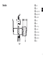
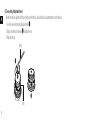
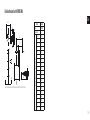
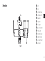
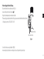
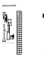
Fig. 1-1
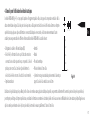
1 Objective lens
2 Eyepiece lens
3 Elevation adjustment turret
4 Windage adjustment turret
5 Eyepiece adjustment
6 Power index
7 Power scale
8 Power selector ring
9 Diopter index dot
0 Rheostat intensity dial
a Rheostat intensity index
b Battery-chamber cover
c Turret cap
1. Nomenclature

8
En
Fr
En
Fr
Ru
Se
Ru
Fi
Cz
Ru
Ru
Se
Ru
Fi
Cz
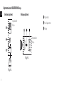
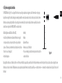
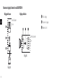
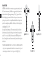
Fig. 1-3
Shipped attached to
riflescope
1 Adjustment turret
2 Screw for adjustment turret
3 Turret cap
Shipped attached to
riflescope
Fig. 1-2
Elevation adjustment Windage adjustment
Adjustment mechanism of BLACK FORCE100 Riescope

9
En
Fr
En
Fr
Ru
Se
Ru
Fi
Cz
Ru
Ru
Se
Ru
Fi
Cz
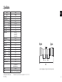
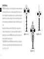
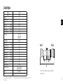
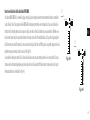
2. Specifications
Model
1-6×24 IL
Reticle
FORCE-MOA
Actual magnification (×) 1-6
Effective objective diameter (mm) 24
Exit pupil
*1
(mm) 24.0-4.0
Eye relief
*1
(in.)/(mm) 3.8-3.7/96.0-94.4
Tube diameter (in.)/(mm) 1.2/30
Objective outside diameter (in.)/(mm) 1.2/30
Eyepiece outside diameter (in.)/(mm) 1.7/44
Adjustment graduation 1 click: 1/4 MOA
*2
1 revolution: 25 MOA
*2
1 revolution: 100 clicks
Max. internal adjustment
100 MOA
*2
Parallax setting (yd.)/(m) 100/91.4
Field of view at 100 yd.
*1
(ft) 111.2-18.3
Field of view at 100 m
*1
(m) 37.1-6.1
Length (a) (in.)/(mm) 11.6/295
Mount length (b) (in.)/(mm)
2.1/54.4
Mount length (c) (in.)/(mm)
1.7/42.0
Mount length (d) (in.)/(mm)
3.2/80.8
Weight (oz)/(g) 20.8/590
Power Source CR2032
Reticle intensity adjustment 10 steps
*3
EMC FCC Part15 subpartB ClassB
CE EMC DIRECTIVE AS/NZS ICES-003
Environment RoHS WEEE
Structure
Waterproof (up to 3 ft 3 in. (1 m) for 10 minutes) and argon gas purged
*1
(at minimum magnication)-(at maximum magnication)
*2
MOA = Minute of Angle
*3
Illumination intensity: 10 steps, with OFF positions between each step (change in the order of 1, OFF, 2, OFF, 3, OFF...10, OFF)
Objective Eyepiece
Letters a to d in the diagram above refer to lengths (a) to (d) shown in the Specifications table.

10
En
Fr
En
Fr
Ru
Se
Ru
Fi
Cz
Ru
Ru
Se
Ru
Fi
Cz
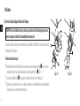
3. Instructions
(1) Inserting the battery and adjusting the illumination intensity
CAUTION: When installing batteries, make sure the rearm is unloaded. Use safe rearm handling
practices at all times.
The IL models (illuminated reticle models) are powered by one 3V lithium battery (CR2032). When your reticle ashes or does not light,
you need to replace the battery.
How to insert the battery
1 Hold the rheostat intensity dial tightly and turn the battery-chamber cover 1 counter-clockwise with the battery-chamber
cover opener 2 (Fig. 3-1).
2 Insert one 3V lithium battery 3 into the chamber with the positive (+) side facing up (Fig. 3-2).
3 Put the cover back and turn it clockwise with the battery-chamber cover opener until the cover is rmly secured.
Fig. 3-1 Fig. 3-2

11
En
Fr
En
Fr
Ru
Se
Ru
Fi
Cz
Ru
Ru
Se
Ru
Fi
Cz
How to adjust the illumination intensity
Turn the rheostat intensity dial to the desired intensity* (Fig.3-3).
When not in use, be sure to set the dial to (OFF).
Illumination will automatically turn o after approximately 2 hours of non-operation.
* The illumination intensity is available in 10 steps. When you rotate the rheostat intensity dial, the illumination intensity changes in the
order of 1, OFF, 2, OFF, 3, OFF...10, OFF.
•
The IL models come with a 3V lithium battery (CR2032).
•
Replace the battery if your riescope is ever submerged in water or if water enters the battery chamber.
Fig. 3-3
Rheostat intensity index
Rheostat intensity dial

12
En
Fr
En
Fr
Ru
Se
Ru
Fi
Cz
Ru
Ru
Se
Ru
Fi
Cz
8
8812
12
16
20
24
12
FORCE-MOA reticle
Fig. 3-4
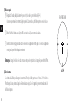
(2) Focusing
1 Look through the eyepiece with your eye positioned about 4 in. (10 cm) away from the eyepiece to see the reticle (Fig. 3-4).
Be sure your eye is positioned with proper alignment and with proper eye relief, otherwise the view will “black out.”
2 Point the objective end of the scope at the sky (do NOT point it at the sun) or at a plain unpatterned wall.
3 Turn the eyepiece adjustment counter-clockwise and then turn it clockwise until the reticle appears sharp.
Notice: Reticle images shown in this manual are representation only. Actual images may vary.
(3) Magnication
•Nikonriescopeshavevariablemagnication.Fordetails,see“2.Specications”.
To change powers, rotate the power selector ring until the desired magnication appears adjacent to the power index.

13
En
Fr
En
Fr
Ru
Se
Ru
Fi
Cz
Ru
Ru
Se
Ru
Fi
Cz
(4) Adjustment of the riescope
Sighting through the riescope, align the rie with your aiming point on the target and shoot a trial round. If the bullet does not hit the aiming point, adjust the elevation and windage adjustment turrets as follows:
•
If the bullet hits under the aiming point, turn the elevation adjustment turret (counter-clockwise) in the direction of the arrow marked “U” for up. If the bullet hits high, turn the elevation adjustment turret (clock-
wise) in the direction of the arrow marked “D” for down.
•
If the bullet hits to the right of the aiming point, turn the windage adjustment turret (clockwise) in the direction of the arrow marked “L” for left. If the bullet hits to the left of the aiming point, turn the windage
adjustment turret (counter-clockwise) in the direction of the arrow marked “R” for right.
Note:
•
The windage and elevation scales of the riescope are calibrated in divisions of 1/4 minute of angle (MOA) with a click at intervals of 1/4 minute of angle (1 division).
•
When adjusting the reticle to the point of aim, remember that 1 minute of angle (MOA) equals approximately 1 in. (2.54 cm) at 100 yd. (91.44 m).
Therefore, if the impact point is 2 in. (5.08 cm) low and 1 in. (2.54 cm) right at 100 yd. (91.44 m) parallax setting, you should adjust 2 minutes of angle up and 1 minute of angle left.
In the case of 50 yd. (45.72 m) parallax setting, the adjusting value is 2×. In the case of 75 yd. (68.58 m) parallax setting, the adjusting value is 1.5×.

14
En
Fr
En
Fr
Ru
Se
Ru
Fi
Cz
Ru
Ru
Se
Ru
Fi
Cz
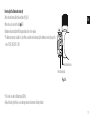
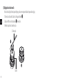
(5) Zero resetting of adjustment turret
After the reticle has been adjusted to match the point of impact, perform the steps described below for each adjustment turret to reset the turret to zero.
1. Loosen the screw on the turret using the included hex key (1).
2. Align the zero number to the index line (2) and tighten the screw.
3. Replace the turret cap.
1
2
Hex key
Turret

15
En
Fr
En
Fr
Ru
Se
Ru
Fi
Cz
Ru
Ru
Se
Ru
Fi
Cz
4. Tips for using tactical reticles
The FORCE-MOA reticle (Fig. 4-1) was designed for both reaction-speed target acquisition and engagement, and for intermediate-to-long-range
target holdovers using the hash mark aiming points extending beneath the center dot and extended crosshair. As with any tactical reticle, the more
information you have regarding the ballistics of your cartridge, the environmental factors and other variables, the better you will be able to use the
various features designed into the FORCE-MOA. These variables include:
•BulletConfigurationandBallisticCoefficient(B.C.)
•ActualVelocity(Ammunitionmanufacturers’informationinregards
to muzzle velocity may or may not match the velocity your firearm
produces. The best way to determine the actual muzzle velocity for your
firearm is to use a chronograph.)
•AmbientTemperature
•Humidity
•Altitude
•BarometricPressure
•Inherentaccuracyofthefirearm
•Thescopemountingsystemandhowtrueitpositionstheoptictothe
centerline of the bore
By using ballistic software, such as Nikon Spot On or one of the many other ballistic apps available, you will be able to eectively determine precise reticle hold points for any load and any distance by using the above
informationasitrelatestothereticle’sMOAsubtensionsandyourparticularsituation.Remember,itisvitalthatyourriescope—andthusthereticle—ismountedtobecompletelyleveland“squared”totheactionof
the rearm.
Fig. 4-1
8
812
12
16
20
24

16
En
Fr
En
Fr
Ru
Se
Ru
Fi
Cz
Ru
Ru
Se
Ru
Fi
Cz
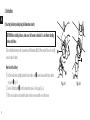
The FORCE-MOA reticle
The FORCE-MOA is a multi-function, glass-etched reticle designed to enable continuous momentum shooting
from target to target, and thus excels in close-to-medium range engagements. When the riescope is set at
itslowest1×magnication,thereticle’silluminatedcenterdotservesasaquickreferenceforcenteringonthe
targetwithbotheyesopen,similartoareddotsight.At6×,thereticle’slowerhashmarksprovideholdover
points for longer known ranges as determined through the calculations of your ballistic table or app. (Fig. 4-2,
4-3, 4-4).
Keepingthereticle’svariousreferencepointsandhashmarksinmind,split-secondrangeestimatescan
be made easily for shooting both up-close at 1× or at longer ranges using the full 6× magnication*. By
knowingyourtarget’ssizeyoucanusetheFORCE-MOAtoestimaterange,andforotherapplicationssuchas
holdovers, windage hold-os and moving target leads.
*TheBLACKFORCE100RiescopehastheFORCE-MOAreticleplacedintheriescope’ssecondfocalplane,so
all holdover corrections, ranging and other measurements using the indicated reticle subtensions should be
done at 6×. (Fig . 4-2, 4-3, 4-4)
Fig. 4-3: IPSC target
Fig. 4-2: 3-Gun target
Fig. 4-4: Pepper Popper

17
En
Fr
En
Fr
Ru
Se
Ru
Fi
Cz
Ru
Ru
Se
Ru
Fi
Cz
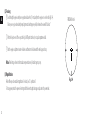
Using FORCE-MOA for wind hold
The BLACK FORCE100 Riescope utilizes capped adjustment turrets to prevent inadvertent movements during competition or rugged, active use. For
this reason, the FORCE-MOA reticle was designed for fast elevation or windage correction on the initial shot, as well as on any follow-up shots. When
adjusting for wind hold using the reticle, you can use the various subtensions between the center dot and outboard gaps and hash marks on the
reticle’shorizontalwirelikearulertohelpreferenceyourspeciedpoint.Forexample,ifthewindspeedvaluehasyouholding6MOAleft,youwillbe
using the rst vertical hash mark to the right of the center dot as your aiming point (Fig. 4-5).
If you are using the reticle for elevation correction as well as for wind hold, you can establish an aiming point by referencing both the proper vertical
wire circle or hash mark and horizontal reference points, and then visualize the target placement where these points would intersect in the lower right
quadrant of the reticle, as shown (Fig. 4-6).
Fig. 4-5
Fig. 4-6
WIND
WIND

18
En
Fr
En
Fr
Ru
Se
Ru
Fi
Cz
Ru
Ru
Se
Ru
Fi
Cz
Using FORCE-MOA for moving target leads
Moving target leads are very similar to wind holds, although typically much more dicult to master. Instead of “holding into the wind,” you will be
“holding in front of the target” (Fig. 4-7). There are various methods to mathematically calculate the target lead (such as multiplying the bullet ight
time to your target by the speed of the target) to determine the lead as it applies to the various reticle subtend points, and then choosing the correct
hold point.
Fig. 4-7
TARGET MOVING

19
En
Fr
En
Fr
Ru
Se
Ru
Fi
Cz
Ru
Ru
Se
Ru
Fi
Cz
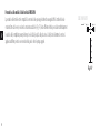
Model 1-6×24 IL
Reticle FORCE-MOA
Magnication (×) 6
Reticle subtensions (at 100 yards)
Unit MOA
A 0.50
B 2.00
C 2.00
D 2.00
E 4.00
F 0.50
G 8.00
H 2.00
I 2.00
J 2.50
K 33.00
L 45.00
M 12.00
N 8.00
O 24.00
P 49.00
Q 25.00
R 1.00
Reticle subtension chart for FORCE-MOA
Letters A to R in the diagram above refer to the reticle subtensions of units A to R shown on the table to the right.
D
K
L
P
O
Q
R
N
G
I
E
J
H
F
B
C
M
A
8
8812
12
16
20
24
12
8
812
12
16
20
24

20
En
Fr
En
Fr
Ru
Se
Ru
Fi
Cz
Ru
Ru
Se
Ru
Fi
Cz
You can use the subtensions shown in this manual, or for rst-shot-rst-hit accuracy in just minutes, use the Nikon Spot On Ballistic Match Technology, free online at NikonSportOptics.com or the FREE Spot On app for iPhone or Android smartphones
or tablets.
Note:
Spot On is available only in the US and Canada.
La page est en cours de chargement...
La page est en cours de chargement...
La page est en cours de chargement...
La page est en cours de chargement...
La page est en cours de chargement...
La page est en cours de chargement...
La page est en cours de chargement...
La page est en cours de chargement...
La page est en cours de chargement...
La page est en cours de chargement...
La page est en cours de chargement...
La page est en cours de chargement...
La page est en cours de chargement...
La page est en cours de chargement...
La page est en cours de chargement...
La page est en cours de chargement...
La page est en cours de chargement...
La page est en cours de chargement...
La page est en cours de chargement...
La page est en cours de chargement...
La page est en cours de chargement...
La page est en cours de chargement...
La page est en cours de chargement...
La page est en cours de chargement...
La page est en cours de chargement...
La page est en cours de chargement...
La page est en cours de chargement...
La page est en cours de chargement...
-
 1
1
-
 2
2
-
 3
3
-
 4
4
-
 5
5
-
 6
6
-
 7
7
-
 8
8
-
 9
9
-
 10
10
-
 11
11
-
 12
12
-
 13
13
-
 14
14
-
 15
15
-
 16
16
-
 17
17
-
 18
18
-
 19
19
-
 20
20
-
 21
21
-
 22
22
-
 23
23
-
 24
24
-
 25
25
-
 26
26
-
 27
27
-
 28
28
-
 29
29
-
 30
30
-
 31
31
-
 32
32
-
 33
33
-
 34
34
-
 35
35
-
 36
36
-
 37
37
-
 38
38
-
 39
39
-
 40
40
-
 41
41
-
 42
42
-
 43
43
-
 44
44
-
 45
45
-
 46
46
-
 47
47
-
 48
48


dans d''autres langues
- English: Nikon BLACK FORCE100 User manual
Documents connexes
-
Nikon BLACK FORCE1000/ BLACK X1000 Manuel utilisateur
-
-
-
-
-
-
-
-
-


